SOUNDCRAFT User Guide
© Harman International Industries Ltd. 1996,1997 All rights reserved Parts of the design of this product may be protected by worldwide patents. Part No. ZM0143 Issue 3 Soundcraft is a trading division of Harman International Industries Ltd. Information in this manual is subject to change without notice and does not represent a commitment on the part of the vendor. Soundcraft shall not be liable for any loss or damage whatsoever arising from the use of information or any error contained in this manual.
Table of Contents 1. Introduction 1.1 Introduction 1.2 Front Panel 1.3 Warranty 1.4 2. Installation 2.1 Dimensions 2.2 Installation 2.3 Precautions and Safety Instructions 2.4 Signal Levels 2.5 Connecting The Inputs 2.6 Connecting The Outputs 2.7 Connections 2.9 3. System Block Diagram 3.1 System Block Diagram 3.2 4. Functional Descriptions 4.1 Stereo Input Channels 1 & 7 - CD/AV 4.2 Stereo Input Channels 2 & 6 - VINYL/CD 4.3 Mono Input Channels 3 & 4 - MIC/LINE Input 4.
ii
1. Introduction D-MIX500 Introduction 1.
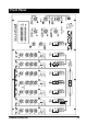
Introduction With a wide variety of choices in both inputs and outputs, the D-MIX500 delivers class-leading flexibility in a cost effective package. A total of seven input channels, four main stereo, one auxiliary stereo and two mono, each with two inputs, will handle up to ten stereo input sources. To keep the DJ fully informed of selected signal sources and outputs, coloured LEDs accompany every major switch on the front panel.
CD2 Front Panel D-MIX500 Introduction 1.
Warranty 1 Soundcraft is a trading division of Harman International Industries Ltd . End User means the person who first puts the equipment into regular operation. Dealer means the person other than Soundcraft (if any) from whom the End User purchased the Equipment, provided such a person is authorised for this purpose by Soundcraft or its accredited Distributor. Equipment means the equipment supplied with this manual.
2. Installation D-MIX500 Installation 2.
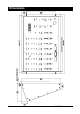
Dimensions 2.
Installation The D-MIX500 is designed for reliability and high performance, and is built to the highest standards. Whilst great care has been taken to ensure that installations are made as troublefree as possible, care taken at this stage, followed by correct setting up will be rewarded by a long life and reliable operation. Wiring Considerations (A) For optimum performance it is essential for the earthing system to be clean and noisefree, as all signals are referenced to this earth.
Precautions and Safety Instructions General Precautions Avoid storing or using the mixing console in conditions of excessive heat or cold,or in positions where it is likely to be subject to vibration, dust or moisture. Do not use any liquids to clean the fascia of the unit: a soft dry brush is ideal. Solvents may cause damage to paint or plastic parts. Avoid using the console close to strong sources of electromagnetic radiation (e.
Signal Levels It is important to supply the correct input levels to the console, otherwise signal to noise ratio or distortion performance may be degraded; and in extreme cases, damage to the internal circuitry may result. Likewise, on all balanced inputs avoid sources with large common-mode DC, AC or RF voltages, as these will reduce the available signal range on the inputs. Note that 0dBu=0.775V RMS. The microphone inputs are designed for use with balanced low impedance (150 or 200 ohms) microphones.
Connecting The Inputs - Examples Example 1 In this example, 2 CD players are connected: one each to channels 1 and 7. There is also a turntable connected to channel 5. The DJ’s mic would normally be plugged into mic 1 (channel 3) via the front panel, and is therefore not shown in this diagram; an additional mic shown is connected to mic 2 (channel 4). This may be used by, for example the MC.
Connecting The Outputs - An Example In the example below, a 2-channel graphic equaliser is connected to the main outputs’ insert points. The main outputs are driving power amps, with speakers on the main dance floor. A secondary dance floor is served by power amps and speakers which are driven by the stereo 2 outputs. A bar or foyer area may have a mono amp and speaker which is, in the example shown, fed from the mono 1 output. D-MIX500 Installation 2.
Connecting the DJ System Outputs - An Example In the example below, the DJ booth amps and speakers are shown fed from the Booth outputs. There is also a tape recorder to record the console’s output, this is connected to the record sockets. Finally, a lighting controller is fed from the lights output. 2.
Connections Wiring conventions The D-MIX500 uses various different types of audio connector: 3-pin XLR , 1⁄4" 3-pole jacks and RCA phono connectors. This section describes how to connect external equipment to the console. Correctly-made cables of the proper type will ensure peak performance from your mixer. Inputs 2. Hot(+ve) 3. Cold(-ve) 1. Screen Balanced Input The mic input accepts XLR-type connectors and is designed to suit a wide range of BALANCED or UNBALANCED low-level signals.
Connections Phono Plugs The phono plug inputs are all unbalanced. The phono inputs are as follows: CD1 Left, CD1 Right, CD2 Left CD2 Right, CD3 Left, CD3 Right CD4 Left, CD4 Signal Right, Vinyl1 Left, Vinyl1 Right, Vinyl2 Left, Vinyl2 Right, Vinyl3 Left, Vinyl3 Right,Input C Left, Input C Right, Monitor Left and Monitor Right. Gnd/Screen The vinyl inputs have RIAA equalisers for turntables. Outputs XLRs The left and right main outputs are on 3-pole male XLR connectors, wired as shown on the left.
Connections Jack Sockets Signal + Impedance Balanced Gnd Gnd All of the jack socket outputs are impedance balanced. They are on 3-pole a gauge jack sockets, wired as shown on the left and below,. They accept 3-pole 1/4" "A" gauge (TRS) jacks, or 2-pole mono jacks. The jack socket outputs are as follows: FX Insert Send, Main Output Insert Send Left, Main Output Insert Send Right, Stereo 2 Left, Stereo 2 Right, Mono1, Mono2, Booth Left, Booth Right and Sound-to-Light.
2.
3. System Block Diagram D-MIX500 System Block Diagram 3.
System Block Diagram 3.
4. Functional Descriptions D-MIX500 Functional Description 4.
Stereo Input Channels 1 & 7 - CD/AV Input Stage (1) The input switch selects the Input source. When this switch is pressed AV 1(2) has been selected and the LED to the right of the switch lights up orange. When the switch is released a green LED will illuminate thus meaning the CD 1(2) Input source has been selected. (2) Gain- Adjusts the level of the selected input by +/-10dB, and should be set up carefully to ensure a good signal level to the rest of the mixer.
Stereo Input Channels 2 & 6 - VINYL/CD Input Stage (1) The input switch selects the Input source. When this switch is pressed CD 4(3) has been selected and the LED to the right of the switch lights up orange. When the switch is released a green LED will illuminate thus meaning the VINYL 1(2) input source has been selected. (2) Gain- Adjusts the level of the selected input by +/-10dB and should be set up carefully to ensure a good signal level to the rest of the mixer.
Mono Input Channels 3 & 4 - MIC/LINE Input 4.
Mono Input Channels 3 & 4 - MIC/LINE Input Input Stage (1) The input switch selects the input source. When this switch is pressed INPUT A(B) has been selected and the LED to the right of the switch lights up orange. When the switch is released a green LED will illuminate thus meaning the MIC 1(2) input source has been selected. (2) Gain- Adjusts the level of the selected input, and should be set up carefully to ensure a good signal level to the rest of the mixer.
Stereo Input Channel 5 - VINYL 3/INPUT C 4.
Stereo Input Channel 5 - VINYL 3/INPUT C Input Stage (9) The input switch selects the input source. When this switch is pressed INPUT C has been selected and the LED to the right of the switch lights up orange. When the switch is released a green LED will illuminate thus meaning the VINYL 3 Input source has been selected. (10) Gain- Adjusts the level of the selected input by +/-10dB and should be set up carefully to ensure a good signal level to the rest of the mixer.
Master Section 4.
Master Section Outputs (1) The Super Bass pot controls the amount of bass sent to the main outputs. This rotary fader injects up to +12dB at 63 Hz. (2) The Balance pot provides a level of adjustment left or right, for the signal feeding the main outputs. This allows compensation for imbalance in the source signal. (3) The Main/Music switch is set to Music when the DJ wants to mute the Mic source from the Main output. When set to Main the music is mixed with the Mic signals from channels 3 and 4.
Master Section 4.
Master Section Monitoring (18) This sends the Record signal directly to the headphones for monitoring. (20) The level of the DJ’s headphones is set by this rotary fader. (21) When Split Cue is pressed, instead of the normal Headphones output being replaced completely by an active Cue signal, the Cue feed appears in the right earphone and a mono mix of the music feed is heard in the left earphone, giving the DJ continuous monitoring of the mixer output if required.
4.
5. Specifications D-MIX500 Specifications 5.
Typical Specifications Input levels CD Input C Vinyl Mic AV & Input A / B Insert return Record monitor 660mV/2V, switchable +4dBu / -10dB, switchable. 5mV @ 1kHz, RIAA equalised. -15dBu to -50dBu, variable. +4dBu. -2dBu -10dBV Input impedances CD & Input C Vinyl Mic AV & Input A / B Main insert return FX insert return Record monitor Greater than 20k ohms, unbalanced. 47k ohms, unbalanced. Greater than 1.5k ohms, balanced. Greater than 20k ohms, balanced. Greater than 20k ohms, balanced.