FIVE Monitor Contents 1
© Harman International Industries Ltd. 1997 All rights reserved Parts of the design of this product may be protected by worldwide patents. Part No. ZM0228 Issue 1 Soundcraft is a trading division of Harman International Industries Ltd. Information in this manual is subject to change without notice and does not represent a commitment on the part of the vendor. Soundcraft shall not be liable for loss or damage whatsoever arising from the use of information or any error contained in this manual.
FIVE Monitor Contents 1. Introduction 1.1 Introduction 1.2 Warranty 1.2 2. Installation 2.1 Dimensions 2.2 Precautions and Safety Instructions 2.3 Mains Installation 2.4 Connections 2.6 Block Diagrams 3.1 24-bus Mono Input Module 3.2 32-bus Mono Input Module 3.3 24-bus Stereo Input Module 3.4 32-bus Stereo Input Module 3.5 32-bus Output Module 3.6 Master Module 3.7 EQ Output Module Functional Description 4.1 Mono Input Module 4.2 Stereo Input Module 4.
ii FIVE Monitor Contents
FIVE Monitor 1 FIVE Monitor Introduction Introduction 1.
Introduction Congratulations on purchasing a Soundcraft console. Series FIVE Monitor is a dedicated Monitor mixing console designed to meet the exacting requirements of major tours and installations.
Warranty 1 Soundcraft is a trading division of Harman International Industries Ltd . End User means the person who first puts the equipment into regular operation. Dealer means the person other than Soundcraft (if any) from whom the End User purchased the Equipment, provided such a person is authorised for this purpose by Soundcraft or its accredited Distributor. Equipment means the equipment supplied with this manual.
1.
FIVE Monitor 2 FIVE Monitor Installation Installation 2.
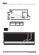
Dimenions 112.35 (4.42") 914.00 (35.98") 251.12 (9.89") 69.64 (2.74") 373.18 (14.69") 284.46 (11.20") 169.38 (6.67") All dimensions are in millimeters (inches in brackets) CONSOLE TOTAL WIDTH WEIGHTS 32-bus, (24-bus, 44ch), 40ch 2007.80 (79.05") 156kg (343lbs) 32-bus, (24-bus, 52ch), 48ch 2269.80 (89.36") 170kg (374lbs) 32-bus, (24-bus, 60ch), 56ch 2531.80 (99.67“) 185kg (407lbs) Mono Input Output Master 40 ch 2.
Precautions and Safety Instructions General Precautions Avoid storing or using the mixing console in conditions of excessive heat or cold, or in positions where it is likely to be subject to vibration, dust or moisture. Do not use any liquids to clean the fascia of the unit: a soft dry brush is ideal. Use only water or ethyl alcohol to clean the trim and scribble strips. Other solvents may cause damage to paint or plastic parts.
Mains Installation General Wiring Procedures To take full advantage of the excellent signal to noise ratio and low distortion of Soundcraft consoles care must be taken to ensure that incorrect installation and wiring does not degrade the performance of the desk. Hum, buzz, instability and Radio Frequency interference can usually be traced to earth loops and inferior earthing systems.
l Connect all microphone lines. By following this sequence much time and future trouble will be saved, and the result will be a quiet, stable system. Shielding Audio equipment is supplied with a variety of input and output configurations, which must be taken into consideration when deciding where the screen connections should be made. There are three sources of unwanted signal being impressed on the screen, which are as follows: l Extraneous electrostatic or electromagnetic fields.
Connections Audio Connectors ALL INPUTS ALL OUTPUTS 3-pole XLR 2 1 3 GROUND (SCREEN) COLD (OUT OF PHASE SIGNAL) HOT (IN PHASE SIGNAL) Socket(female) 1 3 2 Plug(male) / " Stereo Jack Plug used as balanced Input/Output, inc.
Jumper Options Mono Input Module (SC 3917) Jumper JMP 1-6 JMP 7-9 JMP 16-18 JMP 19 JMP 20 Function Channel Insert Position Prefade Source Select GRPS L+R Prefade Source Select GRPS 9-16 Prefade Source Select GRPS 1-8 Direct Output Source Pre EQ Mute Pre Mute Source JMP 21-23 Meter Source JMP 10-12 JMP 13-15 Default J1/2/3 Pre EQ J7 Pre Fade Option J4/5/6 Post EQ J8 Pre Mute Option J10 Pre Fade J11 Pre Mute J12 Pre EQ J13 Pre Fade J14 Pre Mute J15 Pre EQ J18 Post I/P Amp Enabled Post Post EQ I
2.
FIVE Monitor 3 FIVE Monitor Block Diagrams Block Diagrams 3.
3.
FIVE Monitor Block Diagrams FLASH VCA CONTROLS GENERATED BY VCA FADER ASSY MUTE GROUP CONTROLS GENERATED BY MUTE MASTER ASSY +4dBu DIRECT OUT INSERT RETURN +4dBu INSERT SEND INPUT REARCON 8 1 IP SOLO DET MUTE BUS 8 8 1 INPUT A -2 to -70dBu/ +10 to -20dBu INPUT B MUTE MUTE LOGIC MUTE SAFE SOLO LOGIC SOLO OPTIONAL MULTIWAY CONNS + DRILL OUT PADS FOR TRANSFORMER BALANCING B A A/B + - SIMPLIFIED VIEW + DRILL-OUT PADS OPTIONAL MIC/LINE INPUT TX GRP 1-8 PREFADE SOURCE PHANTOM POWE
3.
FIVE Monitor Block Diagrams VCA CONTROLS GENERATED BY VCA FADER ASSY INPUT R INPUT L FLASH MUTE GROUP CONTROLS GENERATED BY MUTE MASTER ASSY INPUT FADER INSERT RETURN +4dBu RIGHT INSERT SEND INSERT RETURN +4dBu LEFT INSERT SEND -2 to -70dBu/ +10 to -20dBu INPUT REARCON 8 1 IP SOLO DET MUTE BUS 8 8 1 L MUTE +48V MUTE LOGIC MUTE SAFE SOLO LOGIC SOLO PHANTOM R VCA CONTROL å SOLO + - + - SIMPLIFIED VIEW + DRILL-OUT PADS OPTIONAL MIC/LINE INPUT TX IN R INSERT R L GRP 1
32-Bus Output Module INSERT MONO/STE MODE BUS GROUP BUS - 32 GRP R GRP L AFL R AFL L PFL ALT AFL R ALT AFL L ALT PFL SEND RETURN OPTIONAL MULTIPIN CONNECTOR PART OF UPPER MASTER REARCON A OUTPUT DRILL-OUT PADS INSERT -2dBu + å DRILL-OUT PADS OPTIONAL EDAC OR TRANSFORMER DIM MUTE +4dBu å 6dB A GROUP OUTPUT POSTMUTE TB SOLO TRIM -6dB SOLO TALKBACK TB DIM - OP SOLO DET MONO OP SOLO INH OP SOLO CLR ALT MUTE MUTE ALL OUTPUTS PREFADE FLASH ±10dB STEREO PART OF UPPER M
OUTPUTS 25 - 32 OUTPUTS 1 - 24 GRP R GRP L ALT AFL R ALT AFL L ALT PFL AFL R PART OF LINK REARCON AFL L PFL Master Module (1) GRP L POSTMUTE ±10dB å DRILL-OUT PADS IN å OPTIONAL EDAC OR TRANSFORMER FADER R WEDGE +4dBu ON WEDGE L OUTPUT 20dB +4dBu _ PART OF UPPER MASTER REARCON PCB SEND -2dBu INSERT RETURN OPTIONAL EDAC OR TRANSFORMER DRILL-OUT PADS WEDGE DIM å _ AFL R + å EXT AFL R INPUT DIM +10dB -2dBu + -2dBu AFL L + WEDGE MONO SOURCE WEDGE INSERT _ EXT AFL L IN
Master Module (2) GRP MONO/STE MODE BUS OUTPUTS 1 - 32 GRP R GRP L AFL R AFL L PFL ALT AFL R ALT AFL L ALT PFL INSERT SEND RETURN OPTIONAL MULTIPIN CONNECTOR PART OF UPPER MASTER REARCON L OUTPUT DRILL-OUT PADS INSERT -2dBu + å OUT FADER +10dB +4dBu MUTE -2dBu - OPTIONAL EDAC OR TRANSFORMER Ø DIM +4dBu å 6dB DRILL-OUT PADS GROUP L OUTPUT OPTIONAL EDAC OR TRANSFORMER TALKBACK TB DIM SOLO OP SOLO DET SOLO TRIM - FLASH TB MONO OP SOLO INH ALT MUTE MONO + SOLO LOG
Master Module (3) PART OF MASTER MODULE LAMP DIM PART OF COMMS LINK/MIDI REARCON IN CALL SIGNAL DETECT COMMS LINK CONSOLE LAMPS FLASH OSCILLATOR CONSOLE LAMPS DIMMER CONSOLE LAMPS OP SOLO INHIBIT OP SOLO DET IP SOLO DET OP SOLO CLEAR IP SOLO CLEAR FLASH VCA BUS 1 - 8 MUTE GROUP 1 - 8 MUTE ALL OUTPUTS VCA SOLO 1 - 8 PART OF MASTER MODULE VCA LEVEL 1 - 8 VCA MUTE 1-8 OUT COMMS LINK/MIDI REARCON FLASH BUS OSCILLATOR MUTE FLASH DISABLE (HIDDEN SWITCH) IN MIDI MERGE PROCESSOR VCA DC L
EQ Output 3.
FIVE Monitor 4 FIVE Monitor Functional Description Functional Description 4.
Input Module 1 SENS (Sensitivity) 2 INPUT A/B - B 3 Ø (Phase) 4 RNGE (Range) 5 48V A and B 6 INS (Insert Point) 7 HPF (Highpass Filter) 8 EQ The SENSitivity Control adjusts the level of the signal which is present on the Input XLRs. The input can handle mic or line level signals up to +30dBu, with the RANGE switch (see below) selecting high or low sensitivity. Every input has A and B XLR inputs, allowing a large number of inputs to be connected to the console without repatching.
HF The HF section is fully sweepable from 1kHz to 20kHz. Q is variable from 0.5 to 3.0, or the band may be switched to a shelving response by turning the Q control fully anticlockwise. HMF The HMF spans the range 500Hz to 8kHz. Q is variable from 0.5 to 3.0. LMF The LMF spans the range 70Hz to 1.5kHz. Q is variable from 0.5 to 3.0. LF The HF section is fully sweepable from 30Hz to 480Hz. Q is variable from 0.5 to 3.
Rr MUTE t MUTE SAFE yI MUTE ASN (Mute Group Assignment) uI VCA ASN (VCA Group Assignment) i SOLO o LED input metering The Channel MUTE switch mutes all feeds from the input channel, and can be remotely controlled by the consoles Mute Master section, allowing creation of up to 8 mute groups. The integral LED illuminates when the Mute is active.
Rearcon Panel The connections on the rearcon panel are as follows: INPUT A and B XLR Pin 1 Pin 2 Pin 3 Gnd (Screen) Hot (In-phase signal) Cold(Out-of-phase signal) DIRECT OUT (Balanced) Pin 1 Pin 2 Pin 3 Gnd (Screen) Hot (In-phase signal) Cold(Out-of-phase signal) INSERT SEND (Balanced) Tip Ring Sleeve Hot (In-phase signal) Cold (Out-of-phase signal) Gnd(screen) INSERT RETURN (Balanced) Tip Ring Sleeve FIVE Monitor Functional Description Hot (In-phase signal) Cold (Out-of-phase signal) Gnd(screen)
Optional Stereo Input Module The optional Stereo module has Left and Right input XLRs and the module may either be configured as a stereo signal path or the Left or Right signals may be fed in mono to both sides of the input. 1 SENS (Sensitivity) 2 RNG (Range) L/R 3 Ø (Phase) 4 48V L and R 5 MNO (Mono) L and R 6 INS (Insert Point) 7 HPF (Highpass Filter) The SENSitivity Control adjusts the level of the signal which is present on the Input XLRs.
8 EQ The stereo EQ section comprises four fully parametric bands, with adjustable Q. Each section has a dual concentric control providing 15dB boost or cut (upper knob) at a variable frequency (lower knob) and a separate Q control. HF The HF section is fully sweepable from 1kHz to 20kHz. Q is variable from 0.5 to 3.0, or the band may be switched to a shelving response by pressing the associated SHELF switch. HMF The HMF spans the range 500Hz to 8kHz. Q is variable from 0.5 to 3.0.
L R 1 2 3 4 7 6 7 8 1 2 3 4 7 6 7 8 SOLO These pairs of mixes are controlled by the faders in the output modules, and are labelled 1A & B (8A & B on 24-bus consoles)to 16A and B. Stereo mode is selected by pressing the Global Mode STE button on the respective output module. The sends are muted unless the ON switch is pressed, and may be switched prefader by pressing the PRE switch.
i SOLO o LED input metering The SOLO button is conveniently located below the fader, and provides a mono PFL or stereo AFL feed to the engineers headphones or monitors depending on the mode selection at the Master section. The SOLO button can also be activated remotely from a VCA SOLO button, if the channel is assigned to a VCA Group. Intercancel or additive soloing is possible, with or without Input Priority, and solos can be cleared with a single button press (SOLO CLEAR) at the master section.
Output Module The standard Output sections of the 24 and 32 bus frame sizes are very similar, and differ only in the omission of one switch and Matrix labelling. An alternative version of the Output Module is available which offers a full 4-band parametric EQ (see Input module for description) on each output, instead of the Matrix section. This module can be used to reduce the amount of external EQ required, particularly for in-ear monitoring applications.
5 MATRIX MASTER 6 MUTE 7 TB 8 SOLO 9 ALT (SOLO) This control sets the master level for the Matrix and provides 10dB of gain when fully clockwise. The Matrix output is muted when the switch is pressed, and the integral LED illuminates to show that the MUTE is active. Note that TALKBACK may still be sent to that output (if TB is pressed), as it is injected post-mute.
w Ø (Phase) e INSERT (OUT) r GRP TO L/R t SOLO TRIM y GLOBAL MODE (STE) Pressing the Ø (Phase) switch reverses the phase of the output, to allow experimentation for best feedback immunity with a multiple-mic setup. The switch is illuminated when the phase is reversed. The Insert Point consists of separate Send and Return jacks on the rear panel. The Send is normalled to the Return.
Rearcon Panels The connections on the rearcon panes are as follows: All Output XLRs (balanced) Pin 1 Pin 2 Pin 3 Gnd (Screen) Hot (In-phase signal) Cold(Out-of-phase signal) INSERT SEND & RETURN (balanced) Tip Ring Sleeve FIVE Monitor Functional Description Hot (In-phase signal) Cold (Out-of-phase signal) Gnd(screen) 4.
Master Module 1 LAMP DIMMER The Lamp Dimmer controls the voltage to the 4-pin XLR socket which is provided for the connection of Littlites. The pinout is as follows: Pin 1 & 3 +/-12V Pin 4 0v max. current 400mA 2 3 PSU RAILS Three LEDs monitor the status of the power supply rails. MUTE FLASH DISABLE When an input channel MUTE is triggered by the MUTE switch of either a VCA Master or a MUTE master, it will flash to show that it is under the control of a remote trigger.
0 +48V q -30dB w FOH e TO OUTPUTS VIA TB (INT) r CALL The +48V switch applies phantom power to the Talkback mic input XLRs when pressed. The -30dB switch inserts a 30dB pad in the input for use with high level signals or external test generators. The FOH button (momentary/latching, green LED) initiates talkback to the front of house console using either the Soundcraft proprietary Blythphone system, or a Clear-Com compatible intercom system.
L & R OUTPUT SECTION The lower half of the Master module comprises the Left/Right Output, which may be used as two individual outputs or linked as a stereo pair. p a FADER The 100mm fader controls the final level to the electronically balanced output. MUTE The output is muted when the switch is pressed, and the integral LED illuminates to show that the MUTE is active.
The function of the Output SOLO switch is also affected by the GLOBAL MODE (STE) switch. If the mode is mono, each Output SOLO button switches an equal feed at unity gain to each of the AFL left and right busses, and a PFL signal to the PFL bus. If the mode is stereo, the SOLO switches are logic linked as a pair and the AFL feed is changed to stereo, at unity gain. The PFL feed remains mono. The SOLO switches can also remotely control a BSS Varicurve system - see page 4.20 for details.
WEDGE OUTPUT l WEDGE FADER ; MAIN WEDGE ON z MONO SOURCE L/R x WEDGE INSERT (IN) c ALT WEDGE LEVEL v ON b SRC (Source) n PRE m PHONES A stereo 100mm fader is provided for engineers Wedge speakers, and this normally receives the EXT SOLO signal (i.e. no signal, unless another slave console is connected.) Whenever an input or output SOLO button is pressed, the Wedge output switches to the corresponding internal or external PFL or AFL signal.
MUTE MASTERS , MUTE ALL OUTPUTS The MUTE ALL OUTPUTS switch will MUTE every Group and Matrix Output on the console (useful as either a ‘panic’ or ‘desk unattended’ switch). This switch is covered to prevent accidental triggering. . MUTE MASTERS 8 recessed latching buttons control the mute status of any channels assigned to the appropriate mute group. Inputs may be assigned to any combination of the eight master mute busses.
BSS VARICURVE™ REMOTE CONTROL FIVE Monitor may be inserted into the MIDI loop of a BSS FPC-900 Varicurve™ Remote Control and Slave system (see diagram below.) When so connected, pressing a SOLO on an Output of the FIVE Monitor will cause the necessary MIDI command to be sent to the Remote unit to SELECT the EQ associated with that Output, thus automatically bringing the EQ for the SOLO’ed channel onto the remote for editing.
LOGIC IN / LOGIC OUT Rear Panel EDAC connectors are provided to link the logic systems of one FIVE Monitor with a second console in a Master/Slave configuration. See Chapter 2, Installation, for connection details. Rearcon Panel The connections on the Master rear connector panel are as follows: All Audio XLRs Pin 1 Pin 2 Pin 3 Gnd (Screen) Hot (In-phase signal) Cold(Out-of-phase signal) 3-ppole ‘A’ gauge Jack - Inputs/Outpus (inc.
4.
FIVE Monitor 5 FIVE Monitor Specifications Specifications 5.
Typical Specifications Frequency Response Any Input to any output . . . . . . . . . . . . . . . .20Hz - 20kHz, +0/-0.5dB Total Harmonic Distortion All measurements at 20dBu Line In to Direct Out (VCA out) . . . . . . . . . . . . . . . .Less than 0.006% @1kHz Line In to Direct Out (VCA In) . . . . . . . . . . . . . . . .Less than 0.02% @1kHz Line In to Mix Out (VCA out) . . . . . . . . . . . . . . . .Less than 0.008% @1kHz Noise 22Hz - 22kHz bandwidth, unweighted Mic input Equivalent Input Noise . . . .