#15713 GIGRAC User Guide Cover 18/6/04 11:38 am Page 1 GREAT SOUND MADE EASY GigRac is designed and engineered in the UK by Soundcraft, world leaders in professional sound. Soundcraft Harman International Industries Ltd Cranborne House, Cranborne Road, Potters Bar, Herts, EN6 3JN, UK TEL: +44 (0)1707 665000 FAX: +44 (0)1707 660742 EMAIL: info@soundcraft.com Soundcraft USA 8500 Balboa Blvd., Northridge, CA 91329, USA TEL: +1-818-920-3212 FAX: +1-818-920-3208 EMAIL: soundcraft-usa@harman.com www.gigrac.
IMPORTANT Please read this manual carefully before using your GigRac1000st for the first time. © Harman International Industries Ltd. 2004 All rights reserved Parts of the design of this product may be protected by worldwide patents. Part No. ZM0301-01 Issue: 1 Soundcraft is a trading division of Harman International Industries Ltd. Information in this manual is subject to change without notice and does not represent a commitment on the part of the vendor.
CONTENTS IMPORTANT SAFETY INSTRUCTIONS ........................ 4 Introduction ............................................................ 7 Quick Start Guide .................................................... 8 Quick Start Guide Key .............................................. 9 A Note on Channel Use ........................................... 14 Front Panel ........................................................... 15 Master Section ......................................................
IMPORTANT SAFETY INSTRUCTIONS CAUTIONS • To avoid the risk of fire, replace the mains fuse only with the correct type and value fuse, as marked on the rear of the product. • ATTENTION: - Afin de réduire le risque de feu remplacer seulement avec fusible de même type. • MAINS VOLTAGE SELECTION This setting is NOT User Adjustable. The units are capable of operating at either 230V AC or 115V AC mains voltages ±10%. • REPLACING MAINS FUSE Remove the mains lead from the connector.
As the colours of the wires in the mains lead may not correspond with the coloured markings identifying the terminals in your plug, proceed as follows: The wire which is coloured Green and Yellow must be connected to the terminal in the plug which is marked with the letter E or by the earth / ground symbol: The wire which is coloured Blue or White must be connected to the terminal in the plug which is marked with the letter N.
• Unplug this apparatus during lightning storms or when unused for long periods of time. • Refer all servicing to qualified service personnel. Servicing is required when the apparatus has been damaged in any way such as, liquid has been spilled or objects have fallen into the apparatus, the apparatus has been exposed to rain or moisture, the apparatus does not operate normally or has been dropped. • If the power cord is damaged obtain a replacement from your Soundcraft dealer.
Introduction Firstly we’d like to thank you for choosing the Soundcraft GigRac 1000st. We hope you have many happy years together! Features 8 Microphone Inputs 48V Phantom Power for condenser microphones (Inputs 1-4 only) PAD buttons for controlling loud input signals (Inputs 1-4 only) 4 Stereo inputs Treble, Mid and Bass controls Pan/Bal controls Individual volume controls on each channel for Monitor level. Individual volume controls on each channel for Main level.
Quick Start Guide If like most people you can’t wait to use your GigRac for the first time, then use the Quick Start Guide to get things started. The Quick Start Guide covers the following: 1. Connecting up your loudspeakers to the GigRac 2. Plugging in a vocal microphone 3. Adding Treble, Mid or Bass to the signals 4. Plugging in a guitar or stereo keyboard 5.
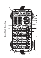
Quick Start Guide Key
1. Connecting up your loudspeakers to the GigRac Note: Make sure your GigRac is not powered up. This is very important to prevent any damage to either the GigRac or your loudspeakers! Using good quality speaker cables connect the loudspeakers to the Speaker outputs on the rear of the GigRac. If you have cables equipped with Neutrik Speakon® connectors then use the Speakon® connectors on the rear of the GigRac.
Turn the Main Master Volume control (1) up to about half-way. Now gradually turn up the Main Volume control (6) on the microphone channel you have chosen to use. You should now hear the microphone signal appearing in the loudspeakers as you begin to speak. You should also be able to see activity on the Output Meter (7). Assuming that you have configured the amps as a stereo pair, you can pan the microphone signal from left to right using the Pan control (8).
3. Adding Treble, Mid or Bass to the signal The GigRac offers Treble, Mid and Bass control for changing the tone of the signal. Treble (9) To add or remove some brightness or ‘sparkle’ to or from a signal, use the Treble control. In the center ‘click’ position (0) the Treble control has no effect. Turning it clockwise will boost the treble frequencies making the signal sound brighter.
4. Plugging in an Acoustic Guitar, Stereo Keyboard or CD Player The GigRac will happily receive signals from instruments with either mono or stereo outputs such as guitars (Mono) or stereo keyboards and CD Players (Stereo). Before plugging in, make sure the Main Volume control (6) for the chosen channel is turned fully off to avoid accidental damage to your speakers. Acoustic Guitars Set the Main Master Volume control (1) to about halfway.
5. Apply one of the 10 GigFX digital effects to the signals The GigRac’s GIGFX Processor (14) has a choice of 10 studio quality digital effects that can be added to any individual or group of signals running through the mixer. Usually vocals require some digital reverb or echo to be added to them in order to create a more spatial sound that is pleasing to the listener. Make sure the ‘effects On’ button (15) is selected.
Front Panel Input channel The GigRac 1000st has a total of 8 channels. Channels 1-4 are designed to handle mono microphone or mono line level signals only. Channels 5-8 are designed to handle mono microphone and stereo line level signals but will also accommodate mono line-level signals as well.
(2) PAD switch (Channels 1-4 only) Pressing the PAD switch reduces the input level by 20dB allowing line or mic level signals that would normally be too loud for the Input stage to handle to be connected without any audible distortion. (3) Main Volume Control The Main Volume Control determines the amount of level sent from the channel to the main output mix.
The FX Bus Output connector could also be used to connect to other external devices such as effects processors or recorders. (7) Bass Control The Bass Control is set at 80Hz and allows you to either add or remove the low frequency content of the signal by 15dB. Rotating the control clockwise will ’boost’ the signal, rotating the control anticlockwise will ‘cut’ the signal.
Master Section 18
(10) Main Master Volume Control This control determines the overall level that is sent to the internal amplification and to the Main Output sockets (22). It also controls the volume of the headphone socket (21). (11) Mon Master Volume Control This control determines the overall level that is sent to the Monitor Output (Mon Output) socket (23). (12) Phantom 48V Switch This switch turns the 48v phantom power On/Off for the 3 pin XLR sockets on channels 1-4.
(15) Amp Clip LEDs The red Amp Clip LEDs illuminate when the input levels to the internal amplifiers are too high. It is acceptable for these LEDs to come on momentarily every now and then but the Main or Monitor Master Volume (depending on which signals have been routed to the amplifiers: see (16) below) should be turned down if the Amp Clip LEDs illuminate consistently.
the Gigrac and allows the playback in signal to be heard without interference from other signal sources. (20) Standby Mute Switch This switch mutes all inputs to the Gigrac except for the signal from the playback in connectors. It also mutes the FX Bus Output and the Monitor Output. The red LED illuminates when the mute is active. See the block diagram for signal routing details. (21) Phones Output Connect headphones to the Phones Output. The Phones Output is driven from the main L and R signals.
(26) FX Bypass Footswitch The FX Bypass Footswitch socket is used for connecting an optional foot switch to turn the GigFX processor On and Off. (27) Effect on switch The effect on switch has a toggle action, the adjacent LED indicates when the FX unit is on. (28) FX to Main Control This controls the volume of Effects sent to the main mix. (29) FX to Mon Control This controls the volume of Effects sent to the monitor mix.
Rear Panel 3 (1) 2 1 Power Switch This switch turns the GigRac On or Off. The red Power LED (14) on the front panel will illuminate to confirm this. NB! Before switching the GigRac On or Off, make sure that the Main and Mon Master Volume controls are turned fully down. (2) Power Socket Connect the supplied power cable to this socket. (3) Speakers Outputs (Amp 1 and Amp 2) The Speaker Outputs are available as Neutrik Speakon® connectors and standard ¼” Jack connectors.
Rackmounting Your GigRac The GigRac 1000st can be rack mounted into a standard 19’’rack. This is useful for fixed instalations or for applications where the GigRac might need to be installed into a portable 19’’ rack along with other equipment. Caution: leave a free 1U space above the Gigrac to allow internal heat to escape. remove 4 rack bolts remove 1 hex socket screw remove gigrac from case. Remove 4 screws that secure strap to side panels and remove strap. Gigrac is now ready for rack mounting.
Using your GigMat GigRac comes supplied with a unique non-slip ‘GigMat’ which can be placed underneath the GigRac when it has to be put onto a slippery surface such as a shiny table top. Under normal circumstances the GigMat will prevent the GigRac from slipping around. If necessary the GigMat can be cleaned using a damp cloth. Please note - it is very important that the GigMat only be used on level surfaces.
Connectors and Leads 28
Block Diagram 29
Warranty 1 Soundcraft is a trading division of Harman International Industries Ltd. End User means the person who first puts the equipment into regular operation. Dealer means the person other than Soundcraft (if any) from whom the End User purchased the Equipment, provided such a person is authorised for this purpose by Soundcraft or its accredited Distributor. Equipment means the equipment supplied with this manual.
Specifications NOISE EIN 150 ohms 20 - 22kHz -123 dBu Main out Level control mid -78 dBu Mon out Level control mid -80 dBu Amp out -57 dBu CROSSTALK Main cutoff -80 dB Mon cutoff -80 dB Frequency Response 20 - 22Khz rel 1kHz Line in to Main out +0.2/-2.5 dB THD+N Mic i/p -20dB Pad 0dBu I/P at Main out (22Hz-22kHz) 0.15% Mic i/p to Amp Out @ full power 22-22kHz 0.15% INPUTS CH1 - CH4 Mic Input Impedance 5.5 kohms Line Input Impedance 30 kohms Max Input Mic ( 20dB pad ) -3.
#15713 GIGRAC User Guide Cover 18/6/04 11:38 am Page 1 GREAT SOUND MADE EASY GigRac is designed and engineered in the UK by Soundcraft, world leaders in professional sound. Soundcraft Harman International Industries Ltd Cranborne House, Cranborne Road, Potters Bar, Herts, EN6 3JN, UK TEL: +44 (0)1707 665000 FAX: +44 (0)1707 660742 EMAIL: info@soundcraft.com Soundcraft USA 8500 Balboa Blvd., Northridge, CA 91329, USA TEL: +1-818-920-3212 FAX: +1-818-920-3208 EMAIL: soundcraft-usa@harman.com www.gigrac.