M-SERIES USER GUIDE ®
SAFETY GUIDE Page USER GUIDE Safety Symbol Guide 2 Approvals and Notice 3 Warranty 4 Important Safety Instructions 5 Cautions 5 Warnings 6 1
SAFETY SYMBOL GUIDE For your own safety and to avoid invalidation of the warranty all text marked with these Symbols should be read carefully. CAUTIONS Must be followed carefully to avoid bodily injury. WARNINGS Must be observed to avoid damage to your equipment. NOTES Contain important information and useful tips on the operation of your equipment.
IMPORTANT Please read this manual carefully before connecting your Mixer to the mains for the first time. soundcraft@harman.com © Harman International Industries Ltd. 2011 All rights reserved Parts of the design of this product may be protected by worldwide patents. Part No. ZM0252 Issue: 3 0811 Soundcraft is a trading division of Harman International Industries Ltd. Information in this manual is subject to change without notice and does not represent a commitment on the part of the vendor.
WARRANTY 1. Soundcraft is a trading division of Harman International Industries Ltd . End User means the person who first puts the equipment into regular operation. Dealer means the person other than Soundcraft (if any) from whom the End User purchased the Equipment, provided such a person is authorised for this purpose by Soundcraft or its accredited Distributor. Equipment means the equipment supplied with this manual. 2.
IMPORTANT SAFETY INSTRUCTIONS CAUTIONS • To avoid the risk of fire, replace the mains fuse only with the correct type and value fuse, as marked on the rear panel. ATTENTION: - Afin de réduire le risque de feu remplacer seulement avec fusible de même type. MAINS VOLTAGE SELECTION This setting is NOT User Adjustable. Units with serial numbers ending in “SS” or “SM” are capable of operating from 85-240V AC mains voltages.
• Do not install near any heat sources such as radiators, heat resistors, stoves, or other apparatus (including amplifiers) that produce heat. • Do not use this apparatus near water. • Do not defeat the safety purpose of the polarized or grounding type plug. A polarized plug has two blades with one wider than the other. A grounding type plug has two blades and a third grounding prong. The wide blade or the third prong are provided for your safety.
CONTENTS Page USER GUIDE Overview 8 The 10 Second Tutor 8 Introduction 10 Advice for Those Who Push the Boundaries 10 Installation & Safety Precautions 11 Wiring Up 12 Mono Input Channels 16 Stereo Input Channels 19 Master Section 21 Using Your Soundcraft M Series Console 23 Advanced Features 25 Application 1 Live Sound Reinforcement 27 Application 2 Multispeaker Applications 28 Application 3 Places of Worship 28 Application 4 Recording 9 Application 5 Linking Two Soundcraft
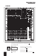
OVERVIEW g f t d ; l h y q 1 2 3 r e v k s j p 4 b 5 a i 6 7 8 w 9 o 0 u z x c To get you working as fast as possible, this manual begins with a 10 second tutorial. Here you can find quick information on any feature of the console, and a page reference where you can find a more detailed explanation. P THE 10 SECOND TUTOR MIC INPUT (XLR) 1 WARNING: Do Not apply Phantom Power before Connect Microphones here.
5 6 7 8 9 0 q w e r EQ STAGE Adjust these controls to change the signal tone AUX SENDS Adjust these controls to change the level of the signal to an FX unit or an artist’s monitors (head phones/in-ear/stage monitors).
INTRODUCTION Thank you for purchasing a Soundcraft mixer. We take great pride in our latest addition to the Soundcraft range of mixing consoles - you have taken a step in the right direction and should never look back. The Packaging in which your Soundcraft M Series arrived forms part of the product and must be retained for future use.
INSTALLATION AND SAFETY PRECAUTIONS ABOUT THIS MANUAL This manual describes the safety precautions, warnings, specifications, installation and operating procedures specific to the following Soundcraft products only: M4 RW5631 UK / EU / US M8 RW5632 UK / EU / US M12 RW5633 UK / EU / US The information in this manual should be read by end users of one of the above products only. In particular, this manual should not be read in conjunction with any other product not listed above.
WIRING UP Please refer to pages 35/36 for additional wiring details. MIC INPUT The mic input accepts XLR-type connectors and is designed to suit a wide range of BALANCED or UNBALANCED low-level signals, whether from delicate vocals requiring the best low-noise performance or close-miked drum kits needing maximum headroom. Professional dynamic, condenser or ribbon mics are best because these will be LOW IMPEDANCE.
STEREO RETURNS RET-1/2/3/4 These accept RCA phono jacks to allow easy connection to hi-fi equipment or DAT players. The input is unbalanced, and ideal for pre-show music sources or signals that do not require any EQ or effects. These can also be used as effect returns using cables described later in this document. STEREO INPUTS STE-1/2/3/4 These accept 3-pole `A’ gauge jacks, or 2-pole mono jacks which will automatically ground the ‘cold’ input.
CHANNEL DIRECT OUTPUTS The Direct outputs are on 3-pole ‘A’ gauge jack sockets, wired as shown on the left, and are impedance balanced. HEADPHONES The PHONES output is a 3-pole ‘A’ gauge jack, wired as a stereo output as shown, suitable for headphones of 200W or greater. 8W headphones are not recommended. POLARITY (PHASE) You will probably be familiar with the concept of polarity in electrical signals and this is of particular importance to balanced audio signals.
PROBLEM SOLVING Basic problem solving is within the scope of any user if a few basic rules are followed. • Get to know the Block Diagram of your console (see page 36). • Get to know what all parameters and/or connection in the system are supposed to do. • Learn where to look for common trouble spots. The Block Diagram is a representative sketch of all the components of the console, showing how they connect together and how the signal flows through the system.
(e-mail: soundcraft.csd@harman.com) MONO INPUT CHANNEL 1 DIRECT OUTPUT The first eight channels have a dedicated Direct Output which allows direct connection to external devices, for example to feed Tape Machines or effects units. 2 MIC INPUT The mic input accepts XLR-type connectors and is designed to suit a wide range of BALANCED or UNBALANCED signals. Professional dynamic, condenser or ribbon mics are best because these will be LOW IMPEDANCE.
tip and ring shorted together so that the signal path is not interrupted (see below). 5 GAIN This knob sets how much of the source signal is sent to the rest of the mixer. Too high, and the signal will distort as it overloads the channel. Too low, and the level of any background hiss will be more noticeable and you may not be able to get enough signal level to the output of the mixer.
0 MUTE All outputs from the channel except inserts are on when the MUTE switch is released and muted when the switch is down, allowing levels to be pre-set before the before the signal is required. The only exception to the muting is any DIRECT OUTPUT configured as PRE-fade, which will be sent regardless of the status of the mute switch.
STEREO INPUT CHANNELS Each stereo input channel comprises two pairs of inputs per channel strip: 1 INPUTS STE-1/2/3/4 These inputs accept 3-pole `A’ gauge (TRS) jacks. Use these inputs for sources such as keyboards, drum machines, synths, tape machines or processing units.
9 FADER The 100mm FADER gives you smooth control of the overall signal level in the channel strip, allowing precise balancing of the various source signals being mixed to the Master Section. It is important that the input level is set correctly to give maximum travel on the fader which should normally be used at around the `0’ mark. See the `Initial Set Up’ section on page 23 for help in setting the right level.
MASTER SECTION 1 PHANTOM POWER Many professional condenser mics need PHANTOM POWER, which is a method of sending a powering voltage down the same wires as the mic signal. Press the switch to enable the +48V power to all of the MIC inputs. The adjacent LED illuminates when the power is active. WARNING: TAKE CARE when using unbalanced mics which may be damaged by the phantom power voltage.
0 MONO SUM t The Mix Left and Right signals are summed to a MONO output on a 3 pole ‘A’ gauge jack . Output level is set by the dedicated rotary control. Monitoring of the Mono output, if required, must be done at the external equipment it feeds, or the signal brought back to a spare console input. q MASTER FADERS The MASTER FADERS set the final level of the MIX outputs, and separate faders are provided for each output.
USING YOUR SOUNDCRAFT M SERIES CONSOLE The final sound from your PA system can only ever be as good as the weakest link in the chain, and especially important is the quality of the source signal because this is the starting point of the chain. Just as you need to become familiar with the control functions of your mixer, so you must recognise the importance of correct choice of inputs, microphone placement and input channel settings.
You are now ready to start building the mix and this should be done progressively, listening carefully for each component in the mix and watching the meters for any hint of overload. If this occurs, back off the appropriate Channel Fader slightly until the level is out of the red segments, or adjust the Master Faders. Remember that the mixer is a mixer, not an amplifier.
DIGITAL OUTPUT Each of the models in the Soundcraft M Series is fitted with a digital output. The output conforms to the S/PDIF standard. The S/PDIF output conforms to the consumer standard IEC958 1989-03, and also the Japanese standard EIAJ CP-340 1987-9 For maximum configurability the Soundcraft M-Series S/PDIF can be sourced from two places.
RACKMOUNTING PROCEDURES FOR M8 AND M12 To turn the sleek looking Soundcraft M Series console into the rugged rackmount version follow the 3 point procedure below: Remove screws at points and remove the arm rest. Remove screws at points and remove the side extrusions. Remove the two screws at points and remove both end-caps. Remember to re-fit the screws as they are used to strengthen the console. Keep all parts and screws carefully in case you need to re-fit them at a later date.
APPLICATION 1 - LIVE SOUND REINFORCEMENT USING DELAY IN REINFORCEMENT SYSTEMS The drawing below illustrates how to calculate delay settings for fill speakers in multiple speaker installations.
APPLICATION 2 - MULTISPEAKER APPLICATIONS This configuration demonstrates how multiple speaker configurations can be driven by the Soundcraft M Range. APPLICATION 3 - PLACES OF WORSHIP This mono configuration uses the Mono output to drive the main speaker system and an induction loop for the hard of hearing. Aux sends are used for monitors and effects and Mix L & R feed a cassette or DAT machine to record the occasion if required.
APPLICATION 4 - RECORDING The direct outputs on channels 1-8 may be used to feed a multitrack recorder as shown. The direct outputs should be set to PRE, so that they are unaffected by fader position. The Mix outputs are used for a preliminary stereo mix on a DAT recorder.
CARE OF YOUR MIXER GENERAL PRECAUTIONS • Do Not obstruct any of the ventilation openings. • Avoid storing or using the mixer in conditions of excessive heat or cold, or in positions where it is likely to be subject to vibration, dust or moisture. • Keep the mixer clean using a soft dry brush, and an occasional wipe with a damp cloth or ethyl alcohol. Do not use any other solvents which may cause damage to paint or plastic parts. • Avoid placing drinks or smoking materials on or near the mixer.
USER GUIDE peak LED a visual indication of the signal peaking just before the onset of clipping. PFL a function that allows the operator to monitor the pre-fade signal (pre-fade listen) in a channel independently of the main mix. phase a term used to describe the relationship of two audio signals. In-phase signals reinforce each other, out-of-phase signals result in cancellation.
TYPICAL SPECIFICATIONS FOR DIGITAL S/PDIF SPECIFICATIONS SEE P.25 NOISE . . . . . . . . . . . . . . . . . . . . . . . . . . . . . . . . . . . . . . . . . . . . . . . . . . . . . . . . . . . . . . . Measured 22Hz to 22kHz, unweighted AUX & MIX O/Ps (8 Channels routed, faders down) . . . . . . . . . . . . . . . . . . . . . . . . . . . . . . . <-84dBu E.I.N. . . . . . . . . . . . . . . . . . . . . . . . . . . . . . . . . . . . . . . . . . . . . . . . . . . . . . . . . . . . . . . . .
M8 & M12 DIMENSIONS All dimensions are in millimetres (Inches shown in brackets).
M4 DIMENSIONS All dimensions are in millimetres (Inches shown in brackets).
APPENDIX 1 - TYPICAL CONNECTING LEADS USER GUIDE 35
36 USER GUIDE
SYSTEM BLOCK DIAGRAM USER GUIDE 37
38 USER GUIDE
CONTROL POSITION MARKUP SHEETS To assist you in restoring the console to a previous setting, e.g. for different bands on a gig, you may photocopy these pages as many times as you like and use them for making a note of your control positions.
40 USER GUIDE
CONTROL POSITION MARKUP SHEETS To assist you in restoring the console to a previous setting, e.g. for different bands on a gig, you may photocopy these pages as many times as you like and use them for making a note of your control positions.
42 USER GUIDE
CONTROL POSITION MARKUP SHEETS To assist you in restoring the console to a previous setting, e.g. for different bands on a gig, you may photocopy these pages as many times as you like and use them for making a note of your control positions.
44 USER GUIDE
USER GUIDE 45
Soundcraft Harman International Industries Limited Cranborne House Cranborne Road Potters Bar Hertfordshire EN6 3JN, UK Tel: +44 (0) 1707 665000 Fax: +44 (0) 1707 660742 Email: soundcraft@harman.com Soundcraft USA 8500 Balboa Boulevard. Northridge CA 91329 USA Tel: 1 818-920.3212 Fax: 1 818-920.3209 Email: soundcraft-usa@harman.com Soundcraft reserve the right to improve or otherwise alter any information supplied in this document or any other document supplied hereafter.