USER GUIDE 1
IMPORTANT Please read this manual carefully before using your mixer for the first time. © Harman International Industries Ltd. 2006 All rights reserved Parts of the design of this product may be protected by worldwide patents. Part No. ZM0342-01 Soundcraft is a trading division of Harman International Industries Ltd. Information in this manual is subject to change without notice and does not represent a commitment on the part of the vendor.
Contents IMPORTANT SAFETY INSTRUCTIONS SAFETY SYMBOL GUIDE INTRODUCTION WIRING UP BLOCK DIAGRAM MONO INPUT CHANNEL STEREO INPUT CHANNELS MASTER SECTION USING YOUR MPM CONSOLE FITTING OPTIONAL RACK-MOUNT BRACKETS (MPM12/2) DIMENSIONS APPLICATIONS TYPICAL CONNECTING LEADS MARK-UP SHEETS TYPICAL SPECIFICATIONS WARRANTY 4 6 7 8 12 13 16 18 22 24 24 25 28 30 31 32 3
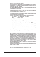
IMPORTANT SAFETY INSTRUCTIONS Read these instructions. Keep these instructions. Heed all warnings. Follow all instructions. Do not use this apparatus near water. Clean only with a dry cloth. Do not block any ventilation openings. Install in accordance with the manufacturer’s instructions. Do not install near any heat sources such as radiators, heat registers, stoves, or other apparatus (including amplifiers) that produce heat. Do not defeat the safety purpose of a polarised or grounding type plug.
with liquids, such as vases, on the apparatus. No naked flame sources, such as lighted candles, should be placed on the apparatus. Ventilation should not be impeded by covering the ventilation openings with items such as newspapers, table cloths, curtains etc. THIS APPARATUS MUST BE EARTHED. Under no circumstances should the safety earth be disconnected from the mains lead. The mains supply disconnect device is the mains plug.
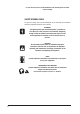
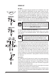
For your own safety and to avoid invalidation of the warranty please read this section carefully. SAFETY SYMBOL GUIDE For your own safety and to avoid invalidation of the warranty all text marked with these symbols should be read carefully. WARNINGS The lightning flash with arrowhead symbol, is intended to alert the user to the presence of un-insulated “dangerous voltage” within the product’s enclosure that may be of sufficient magnitude to constitute a risk of electric shock to persons.
INTRODUCTION Thank you for purchasing a Soundcraft MPM mixer. The MPM range is our most costeffective mixing solution, bringing you all the features and performance that you expect from a Soundcraft product, at an extraordinarily low price. The packaging, which your MPM arrived in, forms part of the product and must be retained for future use.
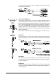
WIRING UP Mic Input The MIC input accepts XLR-type connectors and is designed to suit a wide range of BALANCED or UNBALANCED low-level signals, whether from delicate vocals requiring the best low-noise performance, or drum kits needing maximum headroom. Professional dynamic, condenser or ribbon mics are best because these will be LOW IMPEDANCE.
A ‘Y’ lead may be required to connect to equipment with separate send and return jacks as shown below: Stereo Inputs STEREO 1/2 These accept 3-pole 6.35mm (1/4") jacks, or 2-pole mono jacks which will automatically ground the ‘cold’ input. Use these inputs for sources such as keyboards, drum machines, synths, tape machines or as returns from processing units.
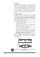
Polarity (Phase) You will probably be familiar with the concept of polarity in electrical signals and this is of particular importance to balanced audio signals. Just as a balanced signal is highly effective at cancelling out unwanted interference, so two microphones picking up the same signal can cancel out, or cause serious degradation of the signal if one of the cables has the +ve and -ve wires reversed.
PROBLEM SOLVING Basic problem solving is within the scope of any user if a few basic rules are followed. • Get to know the Block Diagram of your console (see page 12). • Get to know what all controls and/or connections in the system are supposed to do. • Learn where to look for common trouble spots. The Block Diagram is a representative sketch of all the components of the console, showing how they connect together and how the signal flows through the system.
BLOCK DIAGRAM 12
MONO INPUT CHANNEL 1 Mic Input The MIC input accepts XLR-type connectors and is designed to suit a wide range of BALANCED or UNBALANCED signals. Professional dynamic, condenser or ribbon mics are best because these will be LOW IMPEDANCE. You can use low-cost HIGH IMPEDANCE mics, but the level of background noise will be higher. If you turn the PHANTOM POWER on (top right-hand side of the mixer) the socket provides a suitable powering voltage for professional condenser mics.
The Send may also be tapped off as an alternative pre-fade, pre-EQ direct output if required, using a lead with tip and ring shorted together so that the signal path is not interrupted (see below). 5 Gain This knob sets how much of the source signal is sent to the rest of the mixer. Too high, and the signal will distort as it overloads the channel. Too low, and the level of any background hiss will be more noticeable and you may not be able to get enough signal level to the output of the mixer.
POST-FADE), but for Foldback or Monitor feeds it is important for the send to be independent of the fader (this is called PRE-FADE). AUX SENDS 1 and 2 are both globally switchable between pre and post-fade (see master section on page 21). Aux 3 is always post-fade. 8 PAN This control sets the amount of the channel signal feeding the Left and Right MIX buses, allowing you to move the source smoothly across the stereo image.
STEREO INPUT CHANNELS 1 INPUTS STEREO 1/2 These inputs accept 3-pole 6.35mm (1/4") jacks. Use these inputs for sources such as keyboards, drum machines, synths, tape machines or processing units. The inputs are BALANCED for low noise and top quality from professional equipment, but you can use UNBALANCED sources by wiring up the jacks as shown in the ‘Wiring Up’ section earlier in this manual, although you should then keep cable lengths as short as possible.
7 FADER The 60mm FADER gives you smooth control of the overall signal level in the channel strip, allowing precise balancing of the various source signals being mixed to the Master Section. It is important that the input level is set correctly to give maximum travel on the fader which should normally be used at around the “0” mark. See the “Initial Setup” section on page 22 for help in setting the right level.
MASTER SECTION 18
1 POWER INDICATOR This LED lights to show when power is connected to the console. 2 PHANTOM POWER Many professional condenser mics need PHANTOM POWER, which is a method of sending a powering voltage down the same wires as the mic signal. Press the switch to enable the +48V power to all of the MIC inputs. The adjacent LED illuminates when the power is active. WARNING: TAKE CARE when using unbalanced mics which may be damaged by the phantom power voltage.
12 HEADPHONES SOCKET The PHONES output is a 3-pole 6.35mm (1/4") jack, wired as a stereo output, ideally for headphones of 200Ω or greater. 8Ω headphones are not recommended. 13 METERS & AFL/PFL ACTIVE LED The three-colour peak reading BARGRAPH METERS normally show the level of the signal(s) selected by the monitor source-select switches, giving you a constant warning of excessive peaks in the signal(s) which might cause overloading.
AUX 22 AUX MASTERS These three controls set the output levels of the three Aux Outputs. 23 AFL These After Fade Listen switches route their respective aux output signal to the monitor/headphones outputs. 24 PRE/POST SWITCHES These two switches globally switch the AUX 1 and AUX 2 feeds, respectively, on all the input modules to be either pre-fade or post-fade. AUX 3 is always post fade on the input modules. 25 AUX OUTPUTS 1, 2 & 3 These outputs are on 3-pole 6.35mm (1/4") jacks and are balanced.
USING YOUR MPM CONSOLE The final output from your sound system can only ever be as good as the weakest link in the chain, and especially important is the quality of the source signal because this is the starting point of the chain. Just as you need to become familiar with the control functions of your mixer, so you must recognise the importance of correct choice of inputs, microphone placement and input channel settings.
• • Repeat this procedure on other channels as required. As more channels are added to the mix, the meters may move into the red section. Adjust the overall level using the Master Faders if necessary. Listen carefully for the characteristic sound of “feedback”. If you cannot achieve satisfactory input level setting without feedback, check microphone and speaker placement and repeat the exercise.
FITTING OPTIONAL RACK-MOUNT BRACKETS (MPM12/2) The rack-mount kit part number is RW5753 DIMENSIONS 24
APPLICATIONS APPLICATION 1 - LIVE SOUND REINFORCEMENT APPLICATION 2 - MULTISPEAKER APPLICATIONS This configuration demonstrates how multiple speaker configurations can be driven by the EPM.
APPLICATION 3 - PLACES OF WORSHIP This configuration uses the Aux 3 output to drive an induction loop for the hard of hearing. Aux 1 output is used to generate foldback monitoring for the speaker/singer (Aux 2 could also be used for foldback but has been omitted for clarity). The main outputs are used to drive the main speaker system. The record and playback connections are used to pass audio to and from a DAT machine or CDR.
APPLICATION 4 - RECORDING The insert points on channels 1-8 may be used to feed a multitrack recorder as shown (link the send and return signals). The Mix outputs are used for a preliminary stereo mix on a DAT recorder.
TYPICAL CONNECTING LEADS 28
MARK-UP SHEETS 30 You may freely copy these pages, and use them to record the settings used for particular applications/gigs.
WARRANTY 1 Soundcraft is a trading division of Harman International Industries Ltd . End User means the person who first puts the equipment into regular operation. Dealer means the person other than Soundcraft (if any) from whom the End User purchased the Equipment, provided such a person is authorised for this purpose by Soundcraft or its accredited Distributor. Equipment means the equipment supplied with this manual.