USER'S MANUAL 2000.
TABLE OF CONTENTS Introduction..................................................................................................................... 3 Package Contents...................................................................................................... 3 Safety instructions....................................................................................................... 4 Assembling and disassembling the plastic cover...................................
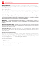
INTRODUCTION Dear Costumers, Congratulations for purchasing a product of the highest quality and technology! SounDigital's products are developed to ensure maximum efficiency and reliability in your audio system. Class D Amplifiers: Class D amplifiers have audio quality, efficiency, application versatility, and compact design as their main features.
SAFETY INSTRUCTIONS To prevent injury to the user or damage to the amplifier, read all the safety instructions contained in this manual; If you feel insecure about installing the equipment, contact SounDigital technical support or a qualified professional in automotive sound installation; Before proceeding with the installation of any electrical equipment in the vehicle, disconnect the negative (-) terminal of the battery to avoid fire, injury or damage to the amplifier; Use your sound system safely, conti
ASSEMBLING AND DISASSEMBLING THE PLASTIC COVER The plastic covers have the function of giving finishing and hiding the amplifier's fixation screws. To remove and replace them, follow the instructions below. DISASSEMBLING THE COVER 1 2 1. Carefully pull the top flap outward, releasing the upper latches, as illustrated in the image. 2. With one continuous movement, slide the plastic cover upward, removing it. COVER ASSEMBLY 1 A B 1.
DESCRIPTION OF THE PANELS 6 9 8 3 2 4 1 7 5 1 CH1 2 CH2 3 CH3 4 CH4 5 CH1/CH2 Crossover Selector Switch 6 CH3/CH4 High Pass - Full - Low Pass 7 CH1/CH2 8 CH3/CH4 9 - RCA audio input Variable gain control Power On" Indicator LED (Blue) 6
DESCRIPTION OF THE PANELS 19 18 15 14 20 17 16 13 12 11 10 21 10 - Negative power connector (GND) 11 - Remote power connector (REM) 12 - Positive power connector (+12VDC) 13 CH4 Positive audio output connector (+) 14 CH4 Negative (-) audio output connector 15 CH3 Conector de saída de áudio positivo (+) 16 CH3 Positive audio output connector (+) 17 CH2 Negative (-) audio output connector 18 CH2 Positive (+) audio output connector 19 CH1 Positive (+) audio output conne
ELECTRICAL SIZING AND AUDIO INPUTS ELECTRICAL SIZING For a correct operation of your SounDigital amplifier, it is necessary to properly size the electrical system and the cables used. In the table below you can determine the minimum proper section of the grounding, positive + 12VDC, and audio output cables according to the amplifier power.
INSTALLATION SEQUENCE CUIDADO! BEFORE INSTALLING ANY ELECTRICAL EQUIPMENT IN THE VEHICLE, DISCONNECT THE NEGATIVE (-) TERMINAL OF THE BATTERY TO AVOID FIRE, DAMAGE TO THE AMPLIFIER AND TO THE USER HIMSELF. FØix the amplifier so that there is access to the connectors. In Østall the power cables in the vehicle in a proper way, starting from the battery up to the fuse holder or circuit breaker, use the cable with the proper section.
CONNECTION DIAGRAM 4-CHANNEL CONFIGURATION See "Audio Input" on page 8 GND 3-CHANNEL CONFIGURATION See "Audio Input" on page 8 GND 10
CONNECTION DIAGRAM / GAIN ADJUSTMENT 2-CHANNEL CONFIGURATION See "Audio Input" on page 8 GND SØet the audio positioning controls in the center (fader and left and right controls); GAIN ADJUSTMENT Equipment required SØet the crossover to "F"; VØoltmeter capable of measuring AC voltage; PØlay 60Hz media on the main unit Øeasure, with the aid of a voltmeter, the M output voltage of the amplifier at the terminals where the speakers were connected; M Øe d i a w i t h 6 0 H z s i n u s o i d a l s i g n a
CROSSOVER ADJUSTMENT X-OVER "F" All frequencies will be played back "LP" Frequencies below 80Hz will be played "HP" Frequencies above 80Hz will be played ØSelect the key in position "F" - All frequencies will be played as in "Figure 1"; dB 0dB -12dB Hz Figure 1 Ø Select the switch in the "HP" position - All frequencies above 80Hz will be played a s in "Figure 2"; dB 0dB -3dB ƒc Hz 80Hz Figure 2 ØSelect the key in the "LP" position - All frequencies below 80Hz will be played as in “Figure 3"; dB
TECHNICAL SPECIFICATIONS 2000.4 PARAMETERS 2000.4 Bridge RMS power @ 2Ω* 2 X 1000W N/A Bridge RMS power @ 4Ω* 2 X 660W 2 X 1000W RMS power @ 1Ω* 4 X 500W N/A RMS power @ 2Ω* 4 X 330W 4 X 500W Frequency response (-3dB) 10Hz ~ 22kHz 10Hz ~ 22kHz Low Pass Filter (LP -12dB/8) 80Hz 80Hz High Pass Filter (HP -12dB/8) 80Hz 80Hz Supply voltage 9V ~ 16V 9V ~ 16V SNR 90dB 90dB Input sensitivity 0.2 ~ 4V 0.
WWW.SOUNDIGITAL.