
Manual

Important Notice to Purchaser:
EXCEPT FOR THE LIMITED WARRANTIES SET FORTH IN THIS DOCUMENT, GLOBAL TRAFFIC TECHNOLOGIES (GTT) MAKES NO OTHER WARRANTIES AND EXPRESSLY DISCLAIMS ALL
OTHER WARRANTIES, WHETHER EXPRESS OR IMPLIED, INCLUDING, WITHOUT LIMITATION, ANY WARRANTY AS TO MERCHANTABILITY OR FITNESS FOR A PARTICULAR USE.
Global Traffi c Technologies (GTT) will, at its sole option, replace or refund any amounts paid for any Opticom™ Infrared System Model 795H Low-Profi le LED Emitter found to be defective
in materials or manufacture within two (2) years from the date of shipment from GTT.
The warranties set forth in this document shall not apply to any Opticom infrared low-profi le emitter which has been (1) repaired or modifi ed by persons not authorized by GTT; (2)
subjected to incorrect installation, misuse, neglect or accident; (3) damaged by extreme atmospheric or weather-related conditions; or (4) subject to events or use outside the normal or
anticipated course.
IN NO EVENT SHALL GTT BE LIABLE FOR ANY INJURY (INCLUDING, WITHOUT LIMITATION, PERSONAL INJURY), DEATH, LOSS, OR DAMAGE (INCLUDING, WITHOUT LIMITATION,
PROPERTY DAMAGE), WHETHER DIRECT, INDIRECT, INCIDENTAL, SPECIAL, CONSEQUENTIAL, OR OTHERWISE, ARISING OUT OF THE USE OR INABILITY TO USE, REPAIR OR FAILURE
TO REPAIR, ANY GTT PRODUCT. REGARDLESS OF THE LEGAL THEORY ASSERTED. THE REMEDIES SET FORTH IN THIS DOCUMENT ARE EXCLUSIVE.
Sale and use of the Opticom infrared system is expressly restricted to authorized agencies of government customers, within their specifi c jurisdictions. However, because the infrared
signal generated by the Opticom infrared system is not exclusive, GTT does not warrant exclusive activation by purchaser. Authorized users who desire to use or coordinate use of the
Opticom infrared system with that of other jurisdictions must fi rst obtain the prior written approval of each authorized user in the jurisdiction where use is sought.
OPTICOM™ INFRARED SYSTEM
- MODEL 795H LOW-PROFILE LED
EMITTER FOR EPL9000
EPL9000 OPTICOM
• Warning devices are strictly regulated and governed by Federal,
State and Municipal ordinances. These devices shall be used
ONLY on approved vehicles. It is the sole responsibility of the user
of these devices to ensure compliance.
EPL9000 OPTICOM 1.10
Important Information:
Input Voltage Range:
10 - 32 Vdc
Current Consumption: 200mA@13.5Vdc (nominal)
1. Description
The Opticom™ Infrared System Model 795 Low-Profi le LED
Emitter is a LED preemption emitter designed for use in low
profi le light bars.* This product is intended for use only inside
of a light bar. It is not intended to be installed in an unprotected
environment.
The Model 795 is intended to be installed by Original
Equipment Manufacturers (OEMs) or an OEM approved
light bar installer only. This document is intended for use by
OEM and their approved installers only. This manual is not
intended for use by end users. The OEM should modify its
lightbar manuals to document proper programming, testing,
use, and maintenance of the Model 795 and provide this
information to the end users.
2. Intended Use
The system is intended to assist authorized priority vehicles
through signalized intersections by providing temporary right-of-
way through vehicle operator interface to the system and through
the use of common traffi c controller functions.
3. OEM Technical Support
If the OEM has questions about the use, installation or operation
of the Model 795, please contact the Global Traffi c Technologies
(GTT) Technical Service department at 1-800-258-4610.
OEMs should direct their end customers to the OEM technical
support contacts in order to answer specifi c questions about how
the Model 795 is installed and wired into their lightbars.
*The method of using the components of the Opticom™ Infrared
system may be covered by U.S. Patent Number 5172113. Other
U.S. and foreign patents pending.
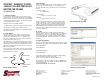
5. Connector Details
The Model 795 is equipped with a 7.5” pigtail with an 8-pin Tyco/AMP
connector. The OEM shall provide the harness to mate with the Model
795 connector.
The part numbers to construct a mating connector are:
Connector Shell: Tyco /AMP, 794941 Qty 1
Connector Pins: Tyco/AMP, 770903 Qty 7
Bulk cable is available from GTT in 1000’ spools. The part number
of this cable is 79-1000-0182-0. If this cable is not used, GTT
recommends that stranded wire 18-22 AWG with colors matching the
Model 795 cable be used when building a mating harness. All seven
wires should be included in the mating harness to provide all
possible functions to the end user.
Power should be connected to a point that will provide suffi cient
voltage and current.
A 1 amp fuse is required to protect vehicle wiring (not included).
6. Connector Pin Out
•RED wire is used to supply +12 Vdc to power the emitter
•BLACK wire is used to provide DC power ground
•WHITE wire is the input for the disable feature (See section 9)
•GREEN wire is a DC return for an indicator light (See section 10)
•GRAY and BLUE wires are used for J-1708 communications (See
Section 11)
•ORANGE wire is used for range setting. This wire is typically
not used in emergency vehicles. GTT recommends that this wire
be pinned out but left unconnected.
Install a 1-amp fuse in series with the red
wire. Failure to install the correct size fuse
may damage the unit and vehicle wiring and
void the warranty.
!
Install a 1-amp fuse in series with the red
wire. Failure to install the correct size fuse
may damage the unit and vehicle wiring and
void the warranty.
CAUTION
CONNECTOR PIN ASSIGNMENTS
PIN #: WIRE COLOR: DESCRIPTION
1 GREY
SERIAL
COMMUNICATION (B)
2 WHITE DISABLE (INPUT)
3 ORANGE
RANGE SETTING
ENABLE
4 RED +12Vdc
5 NOT USED NOT USED
6BLUE
SERIAL
COMMUNICATION (A)
7 BLACK DC GROUND
8 GREEN
DC RETURN FOR
INDICATOR LIGHT
Connector End View
!
CAUTION
Do not cut off the connector. Cutting off the
connector will void the warranty. It will also
prevent end users from programming their
emitter.
4. Electrical Specifi cations