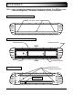
0-16 Volt Version OWNER’S MANUAL & INSTALLATION INSTRUCTIONS EPX3000 8.
TABLE OF CONTENTS Page 2 PAGE CONTENT 3 TECHNICAL SPECIFICATIONS 4 PRE-INSTALLATION 5 APEX BASICS 6 FIXED HEIGHT BRACKETS AND HOOK MOUNTING 7 FIXED HEIGHT BRACKETS PERMANENT MOUNTING 8 GASKET MOUNTING INSTRUCTIONS 9-10 ELECTRICAL INSTALLATION 11 BREAKOUT BOX 12 FLASH PATTERNS AND CONNECTOR INSTRUCTIONS 13 CONTROLLER AND WIRE HARNESS INSTRUCTIONS 14 APEX TROUBLESHOOTING 15 REPLACEMENT PARTS 16 PRODUCT MAINTENANCE BACK WARRANTIES AND POLICIES
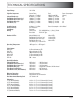
TECHNICAL SPECIFICATIONS Input Voltage 10 - 16Vdc Light Bar Component Current Draw (Average = Flashing) 0.5Amps @ 12.8Vdc 1.0Amps @ 12.8Vdc 1.0Amps @ 12.8Vdc .25Amps @ 12.8Vdc 0.5Amps @ 12.8Vdc Inboard Module (ea): End Module Front Corner (ea): End Module Rear Corner (ea): End Module Alley (ea): Take Down (ea): Peak (100% Steady ON) 1.0Amps @ 12.8Vdc 2.0Amps @ 12.8Vdc 2.0Amps @ 12.8Vdc .50Amps @ 12.8Vdc 1.0Amps @ 12.8Vdc Power Consumption (Watts) 6.4 12.8 12.8 3.2 6.
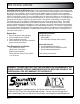
PRE-INSTALLATION IMPORTANT NOTICE TO INSTALLER: Make sure to read and understand all instructions and warnings before proceeding with the installation of this product. Ensure that the manual and any warning cards are delivered to the end user of this equipment. Proper installation of the lightbar requires the installer to have a thorough knowledge of automotive electronics, systems, and procedures. Lightbars provide an essential function of an effective visual warning system.
APEX BASICS This is a basic configuration showing many of the features offered. Your APEX may have a different configuration. This diagram should only be used as a reference.
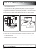
FIXED HEIGHT BRACKETS AND HOOK MOUNTING 1. Loosen lower air deflectors at each end of bar using 10mm socket. Then slide air deflectors toward center of bar to access position for fixed height mounting brackets. 2. Mount fixed height brackets (See Figure 1) using supplied M6x16mm hex bolts on each side. Temporarily place the lightbar in its correct position on the roof of the vehicle. The bar should be positioned about the center line of the “B” pillar.
FIXED HEIGHT BRACKETS PERMANENT MOUNTING 1. Locate the permanent hardware kit that is included. Kit will include (4) 6mm x 16mm hex head bolts, (4) lock washers, (4) hex nuts. 2. Attach fixed height brackets to lightbar using M6 Hex bolts, nuts and lock washers. Brackets should be adjusted to identical positions at both ends of lightbar. See Figure 1. 3. Position the lightbar on the vehicle roof in the desired mounting location. The recommended location is directly above the BPillars.
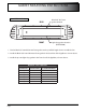
GASKET MOUNTING INSTRUCTIONS BOTTOM VIEW Black 3/8” dia. foam gasket location REAR Light Grey gasket location (PEPX3GA00) FRONT 1. Cut the Black 3/8” round diameter foam gasket to the specified length shown on table below. 2. Install the Black 3/8” round diameter foam gasket in the back slot of the ligthbar as shown above. 3. Install the pre-cut light Grey gasket in the front slot of the ligthbar, as shown above.
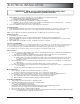
ELECTRICAL INSTALLATION WARNING - CARE MUST BE TAKEN WHEN DRILLING THROUGH THE ROOF OF THE VEHICLE NOT TO DRILL INTO ANY EXISTING WIRING AND NOT TO DRILL THROUGH THE HEADLINER OR SUPPORT MEMBERS OF THE VEHICLE. CHECK BOTH SIDES OF THE MOUNTING SERVICE PRIOR TO DRILLING. DE-BURR ANY HOLES AND REMOVE ANY METAL SHARDS OR REMNANTS. INSTALL GROMMETS INTO ALL WIRE PASSAGE HOLES. WARNING - ROUTE WIRES ONLY IN LOCATIONS THAT ARE NOT SUBJECTED TO POTENTIAL WEAR.
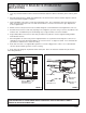
ELECTRICAL INSTALLATION IMPORTANT: When passing cables through firewall or other sheet metal, insert grommet to protect the cable! 2. 3. 4. Install a 40Amp Fuse (customer supplied) to the end of the RED wire of the Lightbar Power Cable. a. Remove the fuse before connecting any wires to the battery. b. DO NOT USE CIRCUIT BREAKER OR FUSIBLE LINK. Connect the other end of the Fuse to the POSITIVE (+) terminal of the battery. a.
BREAKOUT BOX 40Amp FUSE (Customer Supplied) RE D 12 GROUND GA RJ-45 CABLE RED LIGHT No Inputs Input Activated Added Input . DRAIN WIRE GREEN LIGHT Command Rec’d Steady On Has good (See below) connection LOW POWER (STANDBY) MODE If there is no input to the breakout box for 15 seconds, the lightbar will go into a “standby” mode. The standby mode is a low power mode that is used to extend the life of your battery. The green light will turn off when the lightbar enters standby mode.
FLASH PATTERNS AND CONNECTOR INSTRUCTIONS FLASH PATTERN TABLE BREAKOUT BOX HOOKUP: Make sure the 24-pin connector and the RJ-45 connector are snapped in securely. Follow the label for the wire color to connect to a 12Vdc source, which turns on that given light or lights. Make sure your wire connections are secured and isolated from any other wire.
CONTROLLER AND WIRE HARNESS INSTRUCTIONS LIGHT MODULE WIRE HARNESS LOCATIONS FRONT DRIVER SIDE PASSENGER SIDE 37” Bar Green 11 Red 12 Red 13 Green 14 31 Green 32 Red 33 Red 34 Green Blue 11 Green 12 Red 13 Green 14 Blue 15 31 Blue 32 Green 33 Red 34 Green 35 Blue 43” Bar REPLACEMENT OF INBOARD AND END (CORNER) MODULES: 1. Disconnect main power. 2. Remove top cover by removing 3 torx drive screws. 3. Locate module and remove mounting screws or locknuts.
APEX TROUBLESHOOTING NORMAL OPERATION Under Normal operation with lightbar turned on the breakout box will have the Green and Red LED light on steady. When ever you change an input to the lightbar the Red LED on the breakout box will flash then go back to steady. When the lightbar is off (no inputs active) the Green LED on the breakout box will stay on for 15 seconds then go off putting the lightbar into sleep (standby) mode.
REPLACEMENT PARTS STANDARD REPLACEMENT PARTS FOR EPX3000™ Miscellaneous Components ETSWDAS01 Universal Directional Arrow Switch (see website for compatibility) PEPX3E00 Electrical Enclosure 10-16 volt PEPX3E01 Electrical Enclosure 10-30 volt PETLJ00 Electrical Enclosure 10-30 volt PEPL9BBHNL Breakout Box Harness, 36" Length PEPL9BBHNS Breakout Box Harness, 12" Length PEPX3K01 Base Molding & Hardware (pair) - connects the end cap to the extrusion PEPL9RFGR Roof Wire Grommet for External Break Out Box PEPX3GA
PRODUCT MAINTENANCE CLEANING Keeping the lenses clean and scratch free will optimize the performance of the lightbar. To clean use a soft cotton cloth and mild soapy water to clean dirt and insects off from the lenses. Never use window cleaners or harsh chemicals on the lenses; this may cause failure of the lenses or reduce clarity resulting in the reduction of light output. The exterior of the lightbar also should be cleaned with mild soapy water and a soft cotton cloth.
WARRANTY & RETURN GOODS PROCEDURE To review our Limited Warranty Statement & Return Policy for this or any SoundOff Signal product please visit our website at www.soundoffsignal.com and select the “Warranty & Returns” link along the left column of our home page. If you have questions regarding this product please contact Technical Services, Monday - Friday, 8 am to 5 pm at 1.800.338.7337, press #4 to skip the automated message.