
Manual

SoundOff Signal
3900 Central Parkway
Hudsonville, MI 49426
Ph: 800.338.7337
Ph: 616.896.7100
Fx: 616.896.1286
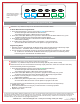
1. Plug in the 8 Gauge Red-Power wire (to battery):
A. Protect the Battery with a 60 Amp fuse (not supplied).
B. The stainless steel “U” grommet on the back of panel
must be removed to install the Red-Power wire and
replaced when finished.
2. Plug in the 2-position wire harness to J5 connector.
A. White - Hot Wire (ignition)
B. Black - Ground Wire
3. Attach the red wire to any power source, preferably the fuse box.
4. Attach the black wire to a clean, unpainted grounding point.
5. The three (3) green/yellow cables control the switch box functions.
6. To make installation easier, all connectors are plug/input specific.
ETSP990 Wiring Instructions
1. If a switch has been associated with the Master
switch, it can always be operated normally by pushing
once (1) to turn ON and a second (2nd) time to turn OFF.
2. If a switch has been associated with and turned on via
the Master switch it can be turned OFF by pushing it one
(1) time.
3. If no buttons are pressed for one (1) minute while in
programming mode, the unit will save the current settings
and exit programming mode automatically.
Operation Notes
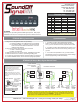
ETSP990 (60 Amps Max) Digital Switch Panel
Warning: In standard format, each switch is ONLY rated for a maximum 10 Amp load per switch!
Should your amp draw requirements exceed 10 Amps per switch, call 800-338-7337 to order our
optional in-line 40 Amp relay kit, part number PSP0RK1. This kit will increase the maximum amp
load capacity of one switch/lead to 40 Amps. List Price is $35.30 each.
Wire
1
2
3
4
5
6
J5
J5
AWG
16
16
16
16
16
16
18
18
8
Color
Grn/Yel
Grn/Yel
Grn/Yel
Grn/Yel
Grn/Yel
Grn/Yel
Black
White
Red
Item
Switch 1
Switch 2
Switch 3
Switch 4
Switch 5
Switch 6
Ground
Ignition
Power
Function
Ground
Ignition
Power
ETSP990
Thank you for purchasing this SoundOff Signal product. With proper
installation and care, this unit will provide years of trouble-free service.
Panel Back Inside View
POWER
+12V
INPUT
8 AWG
15A 15A
1
2
15A
3
4
5
6
J5
TO LOAD
SWS 6
GRN/YEL
16 AWG
TO LOAD
SWS 5
GRN/YEL
16 AWG
TO LOAD
SWS 3
GRN/YEL
16 AWG
TO LOAD
SWS 4
GRN/YEL
16 AWG
GND
BLK
18 AWG
IGN
WHT
18 AWG
TO LOAD
SWS 1
GRN/YEL
16 AWG
TO LOAD
SWS 2
GRN/YEL
16 AWG
Power Connector
Power Terminal
U-Bracket
Use an Available
Bolt/Hole or a
Self Tapping Screw
Star Washer
Ring Terminal
Vehicle Frame
A loose chassis ground
connection WILL cause
intermittent operation!
Chassis Ground
Scrape away any paint from the
selected bolt hole and use a star washer
and ring terminal to ensure a good,
secure electrical connection to the
chassis. The chassis ground must not
be an insulated point.
Note: When drilling into any vehicle
structure, ensure that both sides of the
surface are clear of anything that can be
damaged.
To (-) Black Ground
(12 AWG)
Function column intentionally left blank. Please fill in
appropriate functions and store in glove box for future
reference / tech support.
Function Table
1.800.338.7337 / www.soundoffsignal.com / Thank you for trusting us with your safety!
ETSP990_B.CDR 2010-07-16
Page -1-
NST12020-1_B