
Owner's Manual and Installation Guide 5/3 Channel Power Amplifiers 255, 355, 555


(
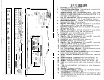
INSTALLATION STEP
4)
LEVEL SEmlNG
The input levels are adjusted by means of the input level controls located on the
front of the amplifier. This is a unique dual-stage circuit that adjusts both level and
gain. This topology maintains better S/N Ratio even when using sources with
minimal output.
In the ideal situation, all components in the audio system reach maximum undistorted
output at the same time. If you send a distorted signal to an amplifier, it is simply
going to amplify distorted information. The same holds true if an outboard proces-
sor or crossover begins to distort before you have maximum output from the ampli-
fier. By setting all components to reach clipping at the same time, you can maxi-
mize the output of your system.
For the
RUBICON
amplifier, follow these steps for
setting the input levels:
1.
Turn the amplifier’s input levels to minimum position (counter-clockwise)
,
\
\
2.
Set the source unit volume to approximately
3/4
of full volume.
I
I
,
3.
While playing dynamic source material, slowly increase the amplifiers’ input
,
level until a near maximum undistorted level is heard in the system.
FRONT SPOILER
Once the amplifier is installed and the
proper levels set, place the front spoi
I
position, and secure it using the suppl
ied
hardware.
4 channels of input
2-way
front/rear fade with constant level bass
4 channels of
2-way
high pass, (rear de-emphasis engaged on
555)
subwoofer channel in low pass
______________-...-_-~-________________---.---_--___-------~.~____--------_~____-----~-~~~~___-------.-..__.
_
_.
.
_
-.
RUBiCGfu255
0
-
cm
r-a
-
0
c.
m
]
!
cnse4*cx14
SLN-
cH2~4.atI~2
cnAnmu2*4
CC
FUSE
tl2V
REMOTE
GND
er in
+12VWDREM
-L+
CHANNELS394
L*
-R+
-