
Owner's Manual and Installation Guide 5/3 Channel Power Amplifiers 255, 355, 555


‘.
‘.
16
1.
2.
3.
4.
5.
6.
7.
8.
9.
10.
11.
12.
13.
14.
15.
16.
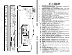
KEY TO
CALLOUTS
Power LED
-
Indicates amplifier power.
Subsonic
/
Hawkins Bass Control Switch
-
Select “SUB SONIC” to
engage the Sub Sonic filter at 13 Hz. Select “HAWKINS BASS CONTROL”
to engage the subwoofer channel’s high pass filter
@I
45 Hz with
+6
dB
boost for optimum bass.
Subwoofer Channel Input Select
-
Selectable inputs; “CH l-4” for non-
fading bass control, “CH 3&4” for front to rear fading bass control.
Channels
3&4
Input Select
-
Selectable inputs from internal (CH
l&2)
or external (CH
38~4
local RCA inputs).
Amp Mode Switch (Channels 1-4)
-
Select “3CH” for bridged mono output
in 3 channel operation (use input channels
1
&
2). Select “5CH” for stereo
output in 5 channel operation.
Inputs
-
Right and left channel RCA inputs for channels
3&4.
Input Level
-
Channels
3&4
input level control.
ltiputs
-
Right and left channel RCA inputs for channels l&2.
Input Level
-
Channels
l&2
input level control.
Sub Input Level
-
Subwoofer channel input level control.
Low Pass Filter Control Adjustment
-
(Subwoofer Channel) crossover
frequency control for the internal low pass filter.
Speaker Connection Terminal
-
Speaker connections for CH l-4
&
Subwoofer Channel.
GND
-
Main ground connection.
Bolt to a clean chassis point in the ve-
hicle.
REMOTE
-
Remote turn-on input from the head unit. Accepts +12V.
+12V
-
Connected to a fuse or circuit breaker, then to the battery’s posi-
tive terminal.
Main Fuse
-
Main power supply fuse.