REFERENCE 705s 5/3 Channel Power Amplifier OWNERS MANUAL AND INSTALLATION GUIDE 1
CONGRATULATIONS! You now own the REFERENCE705s Amplifier, the product of an uncompromising design and engineering philosophy. Your Soundstream REFERENCE amplifier will outperform any other amplifier in the world. To maximize the performance of your system, we recommend that you thoroughly acquaint yourself with its capabilities and features. Please retain this manual and your sales and installation receipts for future reference.
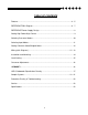
TABLE OF CONTENTS Features .............................................................................................................. 4 - 5 REFERENCE705s Diagram ................................................................................ 6 - 7 REFERENCE Power Supply Design ........................................................................ 8 Setting High Power/High Current ............................................................................. 9 Selecting Crossover Modes.................
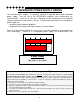
DESIGN FEATURES • Uncompromising Design and Construction including mil-spec glass epoxy circuit boards and high current custom gold-plated solid brass connections that will accept up to 4 gauge power/ground wire.
be stable into any impedance, down to 1/2 ohm. • Six Dual Discrete Class A Drive Stages - Over six times the drive current of most amps, which guarantees maximum performance into any load. TM • Drive Delay Muted Turn-on/off Circuit - A unique circuit which completely eliminates amplifier-related turn-on/off noises. • Flexible Input Sensitivity accepts voltages from 200 mV (80 mV on the subwoofer channel) to 5.0 V, which permits maximum output from the amplifier with virtually any source unit.
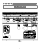
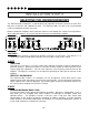
Reference705s 6
Key to Callouts 1. 2. 3. 4. 5. 6. 7. 8. 9. 10. 11. 12. 13. 14. 15. 16. 17. 18. 19. 20. 21. 22. 23. 24. 25. 26. 27. 28. 29. 30. 31. 32. Fault LED - Indicates a blown fuse. High Power LED - Indicates amplifier power on in "High Power" mode. High Current LED - Indicates amplifier power on in "High Current" mode. Main Fuse - Main power supply fuse. +12V - Connected to a fuse or circuit breaker, then to the battery's positive post. GND - Main ground connection. Bolt to a clean chassis ground in the vehicle.
REFERENCE POWER SUPPLY DESIGN The Reference705s employs an extremely efficient unregulated pulse-width modulated power supply. Like the rest of the REFERENCE amplifiers from Soundstream, the Reference705s is rated at 12 volts but is designed to take advantage of the additional voltage available when the vehicle is running.
INSTALLATION STEP 1 SETTING THE HIGH POWER/HIGH CURRENT SWITCH (applies to subwoofer channel only) The Reference705s’ subwoofer channel can be switched between “High Power” and “High Current” modes. This allows the Reference705s to maximize power and efficiency at impedances ≥1 Ohm in “High Power” mode, or down to 1/2 Ohm in “High Current” mode. The circuit operates by selecting a set of power supply voltage rails best suited to your particular application.
INSTALLATION STEP 2 SELECTING THE CROSSOVER MODES The Reference705s incorporates a sophisticated, fully adjustable electronic crossover for each of its two pairs of channels and subwoofer channel. The Reference705s can drive a full system without need of an outboard electronic crossover. Before installing the amplifier, make certain the switches on the bottom are set to the correct positions. After setting the switches, be sure to install the hole plugs included with the amplifier.
INSTALLATION STEP 3 SELECTING INPUT MODES The Reference705s can be driven with either one, two, or three pairs of stereo inputs. If your source unit has front and rear outputs, you can take advantage of its fading capability by driving the Reference705s in 5 channel mode with two pairs of inputs. When operated in the 5 channel mode with 2 pairs of inputs, the lowpass subwoofer channel will operate in a nonfading mode—it derives its signal from the front and rear inputs.
INSTALLATION STEP 4 COHERENT STEREO™ / BRIDGED MONO The stereo channels of the Reference705s have the ability to operate in either of the following modes: Coherent Stereo with identical left and right stereo channels for maximum fidelity. Bridged Mono for dedicated single channel operation; ideal for using the Reference705s in 3channel operation. It is also used when large amounts of power are necessary for single speakers. In bridged mono, only the right channel input (per pair of channels) is active.
WIRING (continued) CIRCUIT BREAKERS/FUSES EXTERNAL Like all car audio amplifiers, the Reference705s must be protected with a fuse or circuit breaker located within 18” of the battery. This will prevent a fire in the event of a shorted cable. The value of the circuit breaker or fuse should be between 60 and 80 amps. INTERNAL The Reference705s is fused on its front panel with a 40 amp Maxi-fuse. In the event of a blown power supply fuse, the “Fault” indicator on the front panel will light.
INSTALLATION STEP 6 INSTALLATION AND MOUNTING 1. AMPLIFIER LOCATION The Reference705s employs highly efficient circuitry and Soundstream's unique ChassisinkTM design to maintain lower operating temperatures. Additional cooling may be required if the amplifier is located in an area with poor air flow, or when driving especially low impedance loads at extremely high levels.
INSTALLATION STEP 7 LEVEL SETTING The input levels are adjusted by means of the input level controls located on the front of the amplifier. This is a unique dual-stage circuit that adjusts both level and gain. This topology maintains better Signal to Noise ratios even with low output sources. In the ideal situation, all components in the audio system reach maximum undistorted output at the same time. The reason is because an amplifier will only make what comes into it bigger.
INSTALLATION STEP 8 CROSSOVER ADJUSTMENTS In most car audio installations, there is a tendency for a “midbass boom.” Because of their interior dimensions, most cars will resonate or ring at these midbass frequencies. If we design the system so there is less musical information in this region, the final response is very smooth and natural sounding. The Reference705s incorporates a continuously variable staggered asymmetrical electronic crossover.
INSTALLATION STEP 9 LSE.Q THEORY AND USE LSE.Q is a proprietary subwoofer control circuit included with the Reference705s amplifier. It is capable of both removing subsonic energy in program material and providing a variable boost at low frequencies. The circuit consists of two controls. One adjusts the frequency of operation, and the other adjusts the range of boost. With both controls adjusted fully counter-clockwise, no boost is applied and the amplifier is flat in response down to 20 Hz. FIG. 1 LSE.
SAMPLE SYSTEM #1 2-way front to rear fade with constant bass 4 channels of input 4 channels of 2-way high pass, sub channel in low pass 18
SAMPLE SYSTEM #2 3-way with midrange bandpass 2 channels of input 2 channels of tweeter high pass, 2 channels of midrange 19
SAMPLE SYSTEM #3 3-way with midbass bandpass and subwoofer to midbass/satellite fading 4 channels of input 2 channels of midbass bandpass, 2 channels of high pass, sub channel in low pass (High Current; < 1 Ohm) 20
SAMPLE SYSTEM #4 2-way in 3 channel mode with fading bass 4 channels of input 2 channels of bridged high pass, sub channel in low pass 21
PROTECTION CIRCUITRY Your Reference705s is protected against both overheating and short circuits by means of the following circuits: • Main power supply fuses (Maxi-fuse at 40 amps) • Smart Power Supply Thermal Rollback activating at 85°C. • A fail-safe thermal protection circuit activating at 95°C. • Self-resetting circuit breakers on channels 1,2,3 & 4 to protect against short circuits. Your amplifier also incorporates an innovative Fault Diagnosis system that identifies a blown power supply fuse.
SERVICE The Reference705s is protected by a limited warranty. Please read the enclosed warranty card. SPECIFICATIONS POWER OUTPUT SUBWOOFER CHANNEL SATELLITE CHANNELS 4 Ω Stereo (8 Ω Bridged) 12 Volts 2 Ω Stereo (4 Ω Bridged) 50 w x 4 (100 w x 2) 100 w x 4 (200 w x 2) Watts 4Ω 12 Volts 2Ω 14.4 Volts 1Ω 14.4 Volts 1/2 Ω 14.4 Volts High 200 w 300 w 400 w n/a High Cur- 100 w 200 w 300 w 400 w THD < 0.1% Signal to Noise > 100 dB Frequency Response 20 Hz to 20 kHz +/- 0.
SOUNDSTREAM TECHNOLOGIES 120 Blue Ravine Road Folsom USA 24 Ca lifornia 95630