
user manual
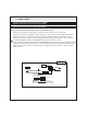


2 Pin Valet/Program/Override Push-Button Switch: (Blue Connector)
The BLACK and GREY twin lead wires loaded in the two pin blue connector are the ground supply and
program/valet/override input of the Remote Start. Drill a 9/32" hole and mount this switch in an easily
accessible location under the driver's dashboard.
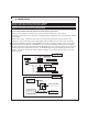
4 Pin Antenna/Receiver Connector: (Black Connector)
Mount the supplied antenna/receiver to a clear spot on the vehicle's winshield that will not block the
driver's vision. A good location is usually high on the winshield near the rear view mirror. Be carefule not
to mount the antenna/receiver on any metallic window film, as this will effect system range. Route the
antenna/receiver cable to the control module and plug into the 4 pin black connector.
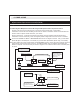
4 Pin 2nd Shock Sensor Port: (White Connector)
The RED (+12 volt), BLACK (ground), BLUE (pre-detect) and GREEN (full trigger when armed) wires
loaded into the white connector shell are the inputs/outputs of the shock sensor.
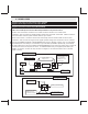
2 Pin LED Harness: (White Connector)
The RED & BLUE wires loaded into the two pin mini white connector control the anode and cathode of
the dash mounted LED. Drill a 1/4" hole and mount the LED in an easy to see location on the
dashboard. Be careful to check to make sure that there is enough clearence behind the panel you are
drilling into.
1. After all connnections are complete, turn the vehicle's ignition key to the ON position.
2. Insert the 30 Amp fuse into the fuseholder.
3. Turn the ignition key to the OFF position.
5. ACCESSORY CONNECTOR'S
6. SYSTEM POWER-UP PROCEDURE