UTO SERIES Robust Metal & Shielded Connector
Overview UTO Series | Contents Contacts 06 07 08 10 12 126 127 128 128 129 131 132 133 Tooling ............................................................... Crimping Instructions ........................................ Handle & Interchangeable Heads ..................... Extraction Tools ................................................. Dimensions Overmoulded Harnesses ............... Assembly Instructions ........................................ Mated Connector Length ...............................
UTO SERIES © 2013 SOURIAU - SOURIAU is a registered trademark
UTO Series Overview Typical Applications ................................................................................................. 06 Features & Benefits ................................................................................................. 07 Range Overview ...................................................................................................... 08 Layouts .................................................................................................................
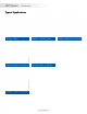
UTO Series | Overview © Olivier Tuffé / Fotolia Instrumentation measurement Telecom - Data infrastructure 6 Building Automation & Control © Sergey Milovidov / Fotolia Robotics - Machine tools © SOURIAU Energy - Power Off road - Mining - Railway © Volodymyr Kyrylyuk / Fotolia © Vibe Images / Fotolia © Rainer Plendl / Fotolia Typical Applications
UTO Series | Overview Features & Benefits IP68/69K Dynamic Mated Ideal for outdoor and indoor dynamic applications requiring continuous underwater immersion, routine pressure washing and dust protection. Overview WATER PROOF EMI Shielded Signal integrity 65 dB at 100 Mhz: Qualified and compatible to be used in electromagnetic radiation areas and ensures proper signal integrity and transmission.
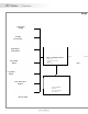
UTO Series | Overview Range Single Wire Sealing Straight Strain Relief Right Angle Strain Relief Choice of Crimp Contacts • machined • stamped and formed • coaxial • fiber optics Short Cable Gland Long Cable Gland UTO Series Heat Shrink Boot Adapter Sealed: IP68/69K Shielded Corrosion resistant UL compliant Overmoulded 8 Plug
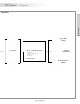
UTO Series | Overview Overview Overview Single Wire Sealing Receptacle Choice of Crimp Contacts • machined • stamped and formed • coaxial • fiber optics Straight Strain Relief PCB Contact Heat Shrink Boot Adapter 9
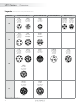
UTO Series | Overview Layouts Shell size (Electrical parameter according to IEC 61984 & IEC 61140) Contact #16 (Ø 1.6) 103 10 104* 6xØ1.0 (#20) 2xØ2.4 (#12) 2xØ1.0 (#20) 3xØ1.6 (#16) 3xØ1.0 (#20) Page 20 Page 36 Page 44 128 1210* 10A 125V 8 contacts 6A 40V 10 contacts Page 52 Page 60 1412 1419 8xØ1.6 (#16) 4xØ1.6 (#16) Page 28 147 16A 150V 6 contacts +ground 10A 150V 12 contacts Page 48 Page 64 12xØ1.6 (#16) 7xØ1.
UTO Series | Overview Contacts #16: from AWG 30 to 14, 0.05 to 2.5 mm² Contacts #20: from AWG 26 to 18, 0.13 to 0.93 mm² Shell size Contacts #8: from AWG 16 to 8, 1.5 to 10 mm² Contacts #12: fromAWG 22 to 12, 0.13 to 4 mm² Contact #16 (Ø 1.6) Contact #20 (Ø 1.0) 1823 1832 8A 150V 23 contacts 4A 50V 32 contacts 23xØ1.6 (#16) 32xØ1.0 (#20) Overview 18 Page 80 2028 Page 96 2030 2041 7A 150V 28 contacts 7A 150V 30 contacts 8A 80V 41 contacts Page 88 Page 92 Page 108 2238 2255 28xØ1.
UTO Series | Overview General technical characteristics Materials Environmental Electrical • Shell: Zinc alloy • Operating temperature: from -40°C to +105°C 40/100/21 per NFF 61-030 • In accordance with: - UL 1977: Certificate ECBT2 File number: E169916 - CSA C22.
Overview UTO Series | Overview 13
UTO SERIES © 2013 SOURIAU - SOURIAU is a registered trademark
UTO Series Connector Upgrade of the UTO Series ..................................................................................... Cable Assembly ....................................................................................................... 2 contacts + ground 103: 10A 500V.................................................................... 142G1: 44A 600V.................................................................... 3 contacts + ground 124: 16A 500V........................................
UTO Series | Connector Upgrade of the UTO Series Old UTO New UTO Description of change: To better meet the demanding requirements and diversity of industrial markets/applications, Souriau changed the position of the wavy washer inside the plug. This slight modification makes the new version of the UTO sealed to IP68/69K in dynamic conditions. Product part number: Below is an overview of the old part numbers with the corresponding new part numbers.
UTO Series | Connector Cable Assembly Connector SOURIAU has provided connectors for various applications for more than 90 years and has been used in the most extreme environments. Conscious about the difficulty in finding a quick and reliable harness manufacturer, we began our own in-house cable assembly production. It allows customers to reduce the number of suppliers and to take advantage of the “best in class” quality of the SOURIAU group.
UTO Series | Connector Overmoulding Description O-ring Thermoplastic insert Compound Overmoulding adapter Braid Cable outer sheath PVC or PUR overmoulding Discrete connector If cable jacket is breached... GOOD ...water ingress unhampered, leading to damage. Overmoulded connector If cable jacket is breached... BEST ...prevents water ingress via capillary action.
UTO Series | Connector UTO Robust Metal & Shielded Cable Assembly Description Connector • • • • Shielded metal connector Extreme sealing: IP68/69K dynamic mated 26 layouts Rapid 1/3 turn connection Cable • TPE outer sheath (black) • 300V • Shielded • Flammability rating UL 1581 Sec.
UTO Series | Connector 103 (Shell size 10, 2 + ground, 3x#16) OR OR OR Layout OR WITH Connector Part Numbers Contact type Contacts supplied separately see page 23 Drilling pattern see page 176 Connector type Sealing Salt spray Square flange receptacle IP67 Plug Part number Male insert Female insert 96h UT00103PH UT00103SH IP68 & IP69K 96h UT00103PH6 UT00103SH6 IP67, IP68 & IP69K 48h UT06103PH UT06103SH IP67, IP68 & IP69K 96h UT06103PH02(Black) UT06103SH02(Black) IP67 48h UT
16A/150V UTO Series | Connector per IEC 61984 103 (Shell size 10, 2 + ground, 3x#16) 2+ Dimensions Square Flange - UTO0 33.3 maxi 11.3 Plug - UTO6 23.8 33 maxi 21.8 Male Ø 20.0 Male Female 1.6 Female 18.2 25.2 maxi 25.5 maxi Jam Nut - UTO7 34 maxi Panel Cut Out Square flange receptacle - UTO0 Ø 3.2 27 Jam nut receptacle - UTO7 Front mounting Ø 14.2 Rear mounting Ø 17.3 Female 17.9 33 maxi 22.2 18.2 16.5 18.2 Ø 14.9 Male .
UTO Series | Connector 103 (Shell size 10, 2 + ground, 3x#16) Accessories and Tooling Dustcap (Receptacle) Dustcap (Plug) Handle (without Head) Tool Kit Part number Part number Part number Part number UT010DCG* UTG610DCG* Shandles Toolkit Gasket Dummy Contact #16 Part number / Neoprene Part number / Polyamide 6.
16A/150V UTO Series | Connector per IEC 61984 103 (Shell size 10, 2 + ground, 3x#16) 2+ Contacts #16 Contact type AWG Crimp Machined Stamped & Formed reeled contacts See note (2) for loose piece PCB Coaxial Max wire Ø Max insulator Ø RC28M1K(1) 0.55 1.00 26-24 RM24M9K RC24M9K 0.80 1.60 22-20 RM20M13K(1) RC20M13K(1) 1.15 1.80 22-20 RM20M12K (1) RC20M12K 1.15 2.20 20-16 RM16M23K(1) RC16M23K(1) 1.80 3.20 16-14 RM14M30K RC14M30K 2.30 3.
UTO Series | Connector 142G1 (Shell size 14, 2 + ground, 3x#8) OR OR OR OR Layout WITH Connector Part Numbers Contact type Contacts supplied separately see page 27 Drilling pattern see page 176 Connector type Sealing Salt spray Square flange receptacle IP67 Plug Part number Male insert Female insert 96h UT00142G1PH UT00142G1SH IP68 & IP69K 96h UT00142G1PH6 UT00142G1SH6 IP67, IP68 & IP69K 48h UT06142G1PH UT06142G1SH IP67, IP68 & IP69K 96h UT06142G1PH02(Black) UT06142G1SH02(Blac
40A/250V UTO Series | Connector per IEC 61984 142G1 (Shell size 14, 2 + ground, 3x#8) 2+ Dimensions Square Flange - UTO0 33.3 maxi 11.3 Plug - UTO6 34 maxi 28.6 29.3 Male Ø 26.8 Male Female 1.6 Female 34 23.0 33 maxi Jam Nut - UTO7 33.9 maxi Panel Cut Out 35 Square flange receptacle - UTO0 Ø 3.2 Jam nut receptacle - UTO7 Front mounting Ø 21.5 Rear mounting Ø 25 Female 17.9 33 maxi 30.2 23.0 24.1 23.0 Ø 22.1 Male .
UTO Series | Connector 142G1 (Shell size 14, 2 + ground, 3x#8) Accessories and Tooling Dustcap (Receptacle) Hand Tool Dustcap (Plug) Part number Part number UT014DCG* UTG614DCG* Part number M317 Gasket Positioner + Locator Setting Part number / Neoprene UTFD14B Part number VGE10078A Extraction Tool #8 Part number 51060210936 * For dustcap without chain, skip "G", e.g.
40A/250V UTO Series | Connector per IEC 61984 142G1 (Shell size 14, 2 + ground, 3x#8) 2+ Contacts PCB Crimp #8 Contact type Machined Machined (2) Part number Male Female Max wire Ø 16 82913601A 82913600A 1.72 14 82913603A 82913602A 2.22 12 82913605A 82913604A 2.82 10 82913607A 82913606A 3.50 8 82913609A 82913608A 4.
UTO Series | Connector 124 (Shell size 12, 3 + ground, 4x#16) Layout OR OR OR OR WITH Connector Part Numbers Contact type Contacts supplied separately see page 31 Drilling pattern see page 176 Connector type Sealing Salt spray Square flange receptacle IP67 Plug Part number Male insert Female insert 96h UT00124PH UT00124SH IP68 & IP69K 96h UT00124PH6 UT00124SH6 IP67, IP68 & IP69K 48h UT06124PH UT06124SH IP67, IP68 & IP69K 96h UT06124PH02(Black) UT06124SH02(Black) IP67 48h UT0
16A/150V UTO Series | Connector per IEC 61984 124 (Shell size 12, 3 + ground, 4x#16) Dimensions 3+ Square Flange - UTO0 33.3 maxi 11.3 Plug - UTO6 33 maxi 26.2 26.1 Male Ø 23.6 Male Female 1.6 Female 25.5 maxi 20.6 25.2 maxi Jam Nut - UTO7 34 maxi Panel Cut Out 32 Square flange receptacle - UTO0 Ø 3.2 Jam nut receptacle - UTO7 Front mounting Ø 18.4 Rear mounting Ø 21.8 Female 17.9 33 maxi 27 20.6 21.0 20.6 Ø 18.9 Male .
UTO Series | Connector 124 (Shell size 12, 3 + ground, 4x#16) Accessories and Tooling Dustcap (Receptacle) Dustcap (Plug) Handle (without Head) Tool Kit Part number Part number Part number Part number UT012DCG* UTG612DCG* Shandles Toolkit Gasket Dummy Contact #16 Part number / Neoprene Part number / Polyamide 6.
16A/150V UTO Series | Connector per IEC 61984 124 (Shell size 12, 3 + ground, 4x#16) Contacts #16 3+ Contact type AWG Crimp Machined Stamped & Formed reeled contacts See note (2) for loose piece PCB Coaxial Max wire Ø Max insulator Ø RC28M1K(1) 0.55 1.00 26-24 RM24M9K RC24M9K 0.80 1.60 22-20 RM20M13K(1) RC20M13K(1) 1.15 1.80 22-20 RM20M12K (1) RC20M12K 1.15 2.20 20-16 RM16M23K(1) RC16M23K(1) 1.80 3.20 16-14 RM14M30K RC14M30K 2.30 3.
UTO Series | Connector 102W2 (Shell size 10, 2x#12 + 2x#20) Layout OR OR OR OR WITH Connector Part Numbers Contact type Contacts supplied separately see page 35 Drilling pattern see page 176 Connector type Sealing Salt spray Square flange receptacle IP67 Plug Part number Male insert Female insert 96h UT00102W2PH UT00102W2SH IP68 & IP69K 96h UT00102W2PH6 UT00102W2SH6 IP67, IP68 & IP69K 48h UT06102W2PH UT06102W2SH IP67, IP68 & IP69K 96h UT06102W2PH02(Black) UT06102W2SH02(Black)
25A/200V UTO Series | Connector per IEC 61984 102W2 (Shell size 10, 2x#12 + 2x#20) Dimensions Square Flange - UTO0 33.3 maxi Plug - UTO6 23.8 11.3 33 maxi 4 21.8 Male Ø 20 Male Female 1.6 Female 18.2 32 maxi 25.5 maxi Jam Nut - UTO7 34 maxi Panel Cut Out 27 Square flange receptacle - UTO0 Ø 3.2 Jam nut receptacle - UTO7 Front mounting Ø 14.2 Rear mounting Ø 17.3 Female 17.9 33 maxi 22.2 18.2 16.5 18.2 Ø 14.9 Male .
UTO Series | Connector 102W2 (Shell size 10, 2x#12 + 2x#20) Accessories and Tooling Dustcap (Receptacle) Dustcap (Plug) Crimp Tooling #20 Part number Part number Part number Part number UT010DCG* UTG610DCG* Shandles Toolkit Gasket Contacts Part number / Neoprene RM/RC 24W3K(1) RM/RC 20W3K(1) RM/RC 18W3K(1) SM/SC 24WL3(1)(2) SM/SC 20WL3(1)(2) UTFD12B Part number of head Contact size S20RCM* S20RCM* S20RCM* S20SCM20* S20SCM20* Standard contacts #20 Ø 1mm (1): Example of plating, for other
25A/200V UTO Series | Connector per IEC 61984 102W2 (Shell size 10, 2x#12 + 2x#20) Contacts #20 Contact type Crimp Machined Stamped & Formed reeled contacts PCB See note (2) for loose piece Machined (3) Part number Male Female Max wire Ø Max insulator Ø 26-24 RM24W3K RC24W3K 0.80 1.60 22-20 RM20W3K RC20W3K 1.15 1.60 20-18 RM18W3K RC18W3K 1.30 2.10 26-24 SM24W3TK6(1)(2) SC24W3TK6(1)(2) - 0.90-1.60 26-24 SM24W3S26 (1)(2) SC24W3S25 - 0.90-1.
UTO Series | Connector 104 (Shell size 10, 4x#16) WITH OR single wire sealing (1) Layout OR OR OR OR WITH Connector Part Numbers Contact type Contacts supplied separately see page 39 Drilling pattern see page 176 Connector type Sealing Salt spray Square flange receptacle IP67 Plug Part number* Male insert Female insert 96h UT00104PH UT00104SH IP68 & IP69K 96h UT00104PH6 UT00104SH6 IP67, IP68 & IP69K 48h UT06104PH UT06104SH(1) IP67, IP68 & IP69K 96h IP67 48h UT07104PH(1) UT
13A/150V UTO Series | Connector per IEC 61984 104 (Shell size 10, 4x#16) Dimensions Square Flange - UTO0 33.3 maxi 11.3 Plug - UTO6 23.8 33 maxi 4 21.8 Male Ø 20 Male Female 1.6 Female 18.2 25.2 maxi 25.5 maxi Jam Nut - UTO7 34 maxi Panel Cut Out 27 Square flange receptacle - UTO0 Ø 3.2 Jam nut receptacle - UTO7 Front mounting Ø 14.2 Rear mounting Ø 17.3 Female 17.9 33 maxi 22.2 18.2 16.5 18.2 Ø 14.9 Male .
UTO Series | Connector 104 (Shell size 10, 4x#16) Accessories and Tooling Dustcap (Receptacle) Dustcap (Plug) Handle (without Head) Tool Kit Part number Part number Part number Part number UT010DCG* UTG610DCG* Shandles Toolkit Gasket Dummy Contact #16 Part number / Neoprene Part number / Polyamide 6.
13A/150V UTO Series | Connector per IEC 61984 104 (Shell size 10, 4x#16) Contacts #16 Contact type Crimp Machined Stamped & Formed reeled contacts See note (2) for loose piece Female Max wire Ø Max insulator Ø 30-28 RM28M1K(1) RC28M1K(1) 0.55 1.00 26-24 RM24M9K(1) RC24M9K(1) 0.80 1.60 22-20 RM20M13K(1) RC20M13K(1) 1.15 1.80 22-20 RM20M12K (1) RC20M12K 1.15 2.20 20-16 RM16M23K(1) RC16M23K(1) 1.80 3.20 16-14 RM14M30K RC14M30K 2.30 3.
UTO Series | Connector 103W3 (Shell size 10, 3x#16 + 3x#20) Layout OR OR OR OR WITH Connector Part Numbers Contact type Contacts supplied separately see page 43 Drilling pattern see page 176 Connector type Sealing Salt spray Square flange receptacle IP67 Plug Part number Male insert Female insert 96h UT00103W3PH UT00103W3SH IP68 & IP69K 96h UT00103W3PH6 UT00103W3SH6 IP67, IP68 & IP69K 48h UT06103W3PH UT06103W3SH IP67, IP68 & IP69K 96h UT06103W3PH02(Black) UT06103W3SH02(Black)
5A/40V UTO Series | Connector per IEC 61984 103W3 (Shell size 10, 3x#16 + 3x#20) Dimensions Square Flange - UTO0 36 maxi Plug - UTO6 23.8 11.3 35 maxi 21.8 Male 6 Ø 20 Male Female 1.6 Female 18.2 25.2 maxi 27 maxi Jam Nut - UTO7 34 maxi Panel Cut Out 27 Square flange receptacle - UTO0 Ø 3.2 Jam nut receptacle - UTO7 Front mounting Ø 14.2 Rear mounting Ø 17.3 Female 17.9 33 maxi 22.2 18.2 16.5 18.2 Ø 14.9 Male .
UTO Series | Connector 103W3 (Shell size 10, 3x#16 + 3x#20) Accessories and Tooling Dustcap (Receptacle) Dustcap (Plug) Handle (without Head) Tool Kit Part number Part number Part number Part number UT010DCG* UTG610DCG* Shandles Toolkit Gasket Dummy Contact #16 Crimp Tooling (without Shandles) Contacts Part number / Neoprene Part number / Polyamide 6.
5A/40V UTO Series | Connector per IEC 61984 103W3 (Shell size 10, 3x#16 + 3x#20) Contacts Female Max wire Ø Max insulator Ø Machined 30-28 26-24 22-20 22-20 20-16 16-14 RM28M1K(1) RM24M9K(1) RM20M13K(1) RM20M12K(1) RM16M23K(1) RM14M30K(1) RC28M1K(1) RC24M9K(1) RC20M13K(1) RC20M12K(1) RC16M23K(1) RC14M30K(1) 0.55 0.80 1.15 1.15 1.80 2.30 1.00 1.60 1.80 2.20 3.20 3.
UTO Series | Connector 106 (Shell size 10, 6x#20) Layout OR OR OR OR WITH Connector Part Numbers Contact type Contacts supplied separately see page 47 Drilling pattern see page 176 Connector type Sealing Salt spray Square flange receptacle IP67 Plug Part number* Male insert Female insert 96h UT0W0106PH UT0W0106SH IP68 & IP69K 96h UT0W0106PH6 UT0W0106SH6 IP67, IP68 & IP69K 48h UT0W6106PH UT0W6106SH IP67, IP68 & IP69K 96h UT0W6106PH02(Black) UT0W6106SH02(Black) IP67 48h UT0W71
7A/80V UTO Series | Connector per IEC 61984 106 (Shell size 10, 6x#20) Dimensions Square Flange - UTO0 33.3 maxi Plug - UTO6 23.8 11.3 33 maxi 21.8 Male 6 Ø 20 Male Female 1.6 Female 18.2 25.2 maxi 25.5 maxi Jam Nut - UTO7 34 maxi Panel Cut Out 27 Square flange receptacle - UTO0 Ø 3.2 Jam nut receptacle - UTO7 Front mounting Ø 14.2 Rear mounting Ø 17.3 Female 17.9 33 maxi 22.2 18.2 16.5 18.2 Ø 14.9 Male .
UTO Series | Connector 106 (Shell size 10, 6x#20) Accessories and Tooling Dustcap (Receptacle) Dustcap (Plug) Handle (without Head) Tool Kit Part number Part number Part number Part number UT010DCG* UTG610DCG* Shandles Toolkit Gasket Crimp Tooling (without Shandles) Part number / Neoprene UTFD12B Contacts Part number of head Contact size RM/RC 24W3K(1) RM/RC 20W3K(1) RM/RC 18W3K(1) SM/SC 24WL3(1)(2) SM/SC 20WL3(1)(2) S20RCM* S20RCM* S20RCM* S20SCM20* S20SCM20* Standard contacts #20 Ø 1m
7A/80V UTO Series | Connector per IEC 61984 106 (Shell size 10, 6x#20) Contacts #20 Contact type Crimp Machined Stamped & Formed reeled contacts PCB See note (2) for loose piece Machined (3) Part number Male Female Max wire Ø Max insulator Ø 26-24 RM24W3K RC24W3K 0.80 1.60 22-20 RM20W3K RC20W3K 1.15 1.60 20-18 RM18W3K RC18W3K 1.30 2.10 26-24 SM24W3TK6(1)(2) SC24W3TK6(1)(2) - 0.90-1.60 26-24 SM24W3S26 (1)(2) SC24W3S25 - 0.90-1.
UTO Series | Connector 147 (Shell size 14, 6 + ground, 7x#16) WITH OR single wire sealing (1) Layout OR OR OR OR WITH Connector Part Numbers Contact type Contacts supplied separately see page 51 Drilling pattern see page 176 Connector type Sealing Salt spray Square flange receptacle IP67 Plug Part number Male insert Female insert 96h UT00147PH UT00147SH IP68 & IP69K 96h UT00147PH6 UT00147SH6 IP67, IP68 & IP69K 48h UT06147PH UT06147SH(1) IP67, IP68 & IP69K 96h IP67 48h UT071
16A/150V UTO Series | Connector per IEC 61984 147 (Shell size 14, 6 + ground, 7x#16) Dimensions Square Flange - UTO0 33.3 maxi Plug - UTO6 33 maxi 28.6 11.3 29.3 Male Male Ø 26.8 6 Female 1.6 Female 25.5 maxi 23.0 25.2 maxi Jam Nut - UTO7 34 maxi Panel Cut Out 35 Square flange receptacle - UTO0 Ø 3.2 Jam nut receptacle - UTO7 Front mounting Ø 21.5 Rear mounting Ø 25 Female 17.9 33 maxi 30.2 23.0 24.1 23.0 Ø 22.1 Male .
UTO Series | Connector 147 (Shell size 14, 6 + ground, 7x#16) Accessories and Tooling Dustcap (Receptacle) Dustcap (Plug) Handle (without Head) Tool Kit Part number Part number Part number Part number UT014DCG* UTG614DCG* Shandles Toolkit Gasket Dummy Contact #16 Part number / Neoprene Part number / Polyamide 6.
16A/150V UTO Series | Connector per IEC 61984 147 (Shell size 14, 6 + ground, 7x#16) Contacts #16 Contact type AWG Crimp Machined Stamped & Formed reeled contacts See note (2) for loose piece PCB Coaxial Max wire Ø Max insulator Ø RC28M1K(1) 0.55 1.00 26-24 RM24M9K RC24M9K 0.80 1.60 22-20 RM20M13K(1) RC20M13K(1) 1.15 1.80 22-20 RM20M12K (1) RC20M12K 1.15 2.20 20-16 RM16M23K(1) RC16M23K(1) 1.80 3.20 16-14 RM14M30K RC14M30K 2.30 3.
UTO Series | Connector 128 (Shell size 12, 8x#16) WITH OR single wire sealing (1) Layout OR OR OR OR WITH Connector Part Numbers Contact type Contacts supplied separately see page 55 Drilling pattern see page 176 Connector type Sealing Salt spray Square flange receptacle IP67 Plug Part number* Male insert Female insert 96h UT00128PH UT00128SH IP68 & IP69K 96h UT00128PH6 UT00128SH6 IP67, IP68 & IP69K 48h UT06128PH UT06128SH(1) IP67, IP68 & IP69K 96h IP67 48h UT07128PH(1) UT0
10A/125V UTO Series | Connector per IEC 61984 128 (Shell size 12, 8x#16) Dimensions Square Flange - UTO0 33.3 maxi 11.3 Plug - UTO6 33 maxi 26.2 26.1 Male Ø 23.6 Male Female 1.6 25.5 maxi 20.6 25.2 maxi Jam Nut - UTO7 34 maxi 8 Female Panel Cut Out 32 Square flange receptacle - UTO0 Ø 3.2 Jam nut receptacle - UTO7 Front mounting Ø 18.4 Rear mounting Ø 21.8 Female 17.9 33 maxi 27 20.6 21.0 20.6 Ø 18.9 Male .2 22 Backshells (for Mated Connector Length: See Page 153) 10.7 Ø 25.
UTO Series | Connector 128 (Shell size 12, 8x#16) Accessories and Tooling Dustcap (Receptacle) Dustcap (Plug) Handle (without Head) Tool Kit Part number Part number Part number Part number UT012DCG* UTG612DCG* Shandles Toolkit Gasket Dummy Contact #16 Part number / Neoprene Part number / Polyamide 6.
10A/125V UTO Series | Connector per IEC 61984 128 (Shell size 12, 8x#16) Contacts #16 Contact type AWG Crimp Machined Stamped & Formed reeled contacts See note (2) for loose piece PCB Coaxial Max wire Ø Max insulator Ø RC28M1K(1) 0.55 1.00 26-24 RM24M9K RC24M9K 0.80 1.60 22-20 RM20M13K(1) RC20M13K(1) 1.15 1.80 22-20 RM20M12K (1) RC20M12K 1.15 2.20 20-16 RM16M23K(1) RC16M23K(1) 1.80 3.20 16-14 RM14M30K RC14M30K 2.30 3.
UTO Series | Connector 148 (Shell size 14, 4x#12 + 4x#16) Layout OR OR OR OR WITH Connector Part Numbers Contact type Contacts supplied separately see page 59 Drilling pattern see page 176 Connector type Sealing Salt spray Square flange receptacle IP67 Plug Part number Male insert Female insert 96h UT00148PH UT00148SH IP68 & IP69K 96h UT00148PH6 UT00148SH6 IP67, IP68 & IP69K 48h UT06148PH UT06148SH IP67, IP68 & IP69K 96h UT06148PH02(Black) UT06148SH02(Black) IP67 48h UT0714
17A/230V UTO Series | Connector per IEC 61984 148 (Shell size 14, 4x#12 + 4x#16) Dimensions Square Flange - UTO0 33.3 maxi Plug - UTO6 35 maxi 28.6 11.3 29.3 Male Ø 26.8 Male 1.6 Female 33 maxi 23.0 32 maxi Jam Nut - UTO7 34 maxi 8 Female Panel Cut Out 35 Square flange receptacle - UTO0 Ø 3.2 Jam nut receptacle - UTO7 Front mounting Ø 21.5 Rear mounting Ø 25 Female 17.9 33 maxi 30.2 23.0 24.1 23.0 Ø 22.1 Male .
UTO Series | Connector 148 (Shell size 14, 4x#12 + 4x#16) Accessories and Tooling Dustcap (Receptacle) Dustcap (Plug) Handle (without Head) Tool Kit Part number Part number Part number Part number UT014DCG* UTG614DCG* Shandles Shandles Toolkit Gasket Dummy Contact #16 Part number / Neoprene Part number / Polyamide 6.
17A/230V UTO Series | Connector per IEC 61984 148 (Shell size 14, 4x#12 + 4x#16) Contacts #16 Contact type Crimp Machined Stamped & Formed reeled contacts See note (2) for loose piece AWG Male Female Max wire Ø Max insulator Ø 30-28 RM28M1K(1) RC28M1K(1) 0.55 1.00 26-24 RM24M9K RC24M9K 0.80 1.60 22-20 RM20M13K(1) RC20M13K(1) 1.15 1.80 22-20 RM20M12K (1) RC20M12K 1.15 2.20 20-16 RM16M23K(1) RC16M23K(1) 1.80 3.20 16-14 RM14M30K RC14M30K 2.30 3.
UTO Series | Connector 1210 (Shell size 12, 10x#20) Layout OR OR OR OR WITH Connector Part Numbers Contact type Contacts supplied separately see page 63 Drilling pattern see page 176 Connector type Sealing Salt spray Square flange receptacle IP67 Plug Part number* Male insert Female insert 96h UT0W01210PH UT0W01210SH IP68 & IP69K 96h UT0W01210PH6 UT0W01210SH6 IP67, IP68 & IP69K 48h UT0W61210PH UT0W61210SH IP67, IP68 & IP69K 96h UT0W61210PH02(Black) UT0W61210SH02(Black) IP67 4
6A/40V UTO Series | Connector per IEC 61984 1210 (Shell size 12, 10x#20) Dimensions Square Flange - UTO0 33.3 maxi 11.3 Plug - UTO6 33 maxi 26.2 26.1 Male Ø 23.6 Male Female 1.6 Female 25.5 maxi 20.6 25.2 maxi Jam Nut - UTO7 34 maxi 10 Panel Cut Out 32 Square flange receptacle - UTO0 Ø 3.2 Jam nut receptacle - UTO7 Front mounting Ø 18.4 Rear mounting Ø 21.8 Female 17.9 33 maxi 27 20.6 21.0 20.6 Ø 18.9 Male .
UTO Series | Connector 1210 (Shell size 12, 10x#20) Accessories and Tooling Dustcap (Receptacle) Dustcap (Plug) Handle (without Head) Tool Kit Part number Part number Part number Part number UT012DCG* UTG612DCG* Shandles Toolkit Gasket Crimp Tooling (without Shandles) Part number / Neoprene UTFD13B Contacts Part number of head Contact size RM/RC 24W3K(1) RM/RC 20W3K(1) RM/RC 18W3K(1) SM/SC 24WL3(1)(2) SM/SC 20WL3(1)(2) S20RCM* S20RCM* S20RCM* S20SCM20* S20SCM20* Standard contacts #20 Ø
6A/40V UTO Series | Connector per IEC 61984 1210 (Shell size 12, 10x#20) Contacts #20 Contact type Crimp Machined Stamped & Formed reeled contacts PCB See note (2) for loose piece Machined (3) Part number Male Female Max wire Ø Max insulator Ø 26-24 RM24W3K RC24W3K 0.80 1.60 22-20 RM20W3K RC20W3K 1.15 1.60 20-18 RM18W3K RC18W3K 1.30 2.10 26-24 SM24W3TK6(1)(2) SC24W3TK6(1)(2) - 0.90-1.60 26-24 SM24W3S26 (1)(2) SC24W3S25 - 0.90-1.
UTO Series | Connector 1412 (Shell size 14, 12x#16) WITH OR single wire sealing (1) Layout OR OR OR OR WITH Connector Part Numbers Contact type Contacts supplied separately see page 67 Drilling pattern see page 176 Connector type Sealing Salt spray Square flange receptacle IP67 Plug Part number* Male insert Female insert 96h UT001412PH UT001412SH IP68 & IP69K 96h UT001412PH6 UT001412SH6 IP67, IP68 & IP69K 48h UT061412PH UT061412SH(1) IP67, IP68 & IP69K 96h IP67 48h UT071412
10A/150V UTO Series | Connector per IEC 61984 1412 (Shell size 14, 12x#16) Dimensions Square Flange - UTO0 33.3 maxi 11.3 Plug - UTO6 33 maxi 28.6 29.3 Male Ø 26.8 Male Female 1.6 Female 25.5 maxi 23.0 25.2 maxi Jam Nut - UTO7 34 maxi 12 Panel Cut Out 35 Square flange receptacle - UTO0 Ø 3.2 Jam nut receptacle - UTO7 Front mounting Ø 21.5 Rear mounting Ø 25 Female 17.9 33 maxi 30.2 23.0 24.1 23.0 Ø 22.1 Male .5 25 Backshells (for Mated Connector Length: See Page 153) 9.5 Ø 29.
UTO Series | Connector 1412 (Shell size 14, 12x#16) Accessories and Tooling Dustcap (Receptacle) Dustcap (Plug) Handle (without Head) Tool Kit Part number Part number Part number Part number UT014DCG* UTG614DCG* Shandles Toolkit Gasket Dummy Contact #16 Part number / Neoprene Part number / Polyamide 6.
10A/150V UTO Series | Connector per IEC 61984 1412 (Shell size 14, 12x#16) Contacts #16 Contact type AWG Crimp Machined Stamped & Formed reeled contacts See note (2) for loose piece PCB Coaxial Max wire Ø Max insulator Ø RC28M1K(1) 0.55 1.00 26-24 RM24M9K RC24M9K 0.80 1.60 22-20 RM20M13K(1) RC20M13K(1) 1.15 1.80 22-20 RM20M12K (1) RC20M12K 1.15 2.20 20-16 RM16M23K(1) RC16M23K(1) 1.80 3.20 16-14 RM14M30K RC14M30K 2.30 3.
UTO Series | Connector 1492 (Shell size 14, 12x#16) Layout OR OR OR OR WITH Connector Part Numbers Contact type Contacts supplied separately see page 71 Drilling pattern see page 176 Connector type Sealing Salt spray Square flange receptacle IP67 Plug Part number* Male insert Female insert 96h UT001492PH UT001492SH IP68 & IP69K 96h UT001492PH6 UT001492SH6 IP67, IP68 & IP69K 48h UT061492PH UT061492SH IP67, IP68 & IP69K 96h UT061492PH02(Black) UT061492SH02(Black) IP67 48h UT07
10A/150V UTO Series | Connector per IEC 61984 1492 (Shell size 14, 12x#16) Dimensions Square Flange - UTO0 33.3 maxi 11.3 Plug - UTO6 33 maxi 28.6 29.3 Male Ø 26.8 Male Female 1.6 Female 25.5 maxi 23.0 25.2 maxi Jam Nut - UTO7 34 maxi 12 Panel Cut Out 35 Square flange receptacle - UTO0 Ø 3.2 Jam nut receptacle - UTO7 Front mounting Ø 21.5 Rear mounting Ø 25 Female 17.9 33 maxi 30.2 23.0 24.1 23.0 Ø 22.1 Male .
UTO Series | Connector 1492 (Shell size 14, 12x#16) Accessories and Tooling Dustcap (Receptacle) Dustcap (Plug) Handle (without Head) Tool Kit Part number Part number Part number Part number UT014DCG* UTG614DCG* Shandles Toolkit Gasket Dummy Contact #16 Part number / Neoprene Part number / Polyamide 6.
10A/150V UTO Series | Connector per IEC 61984 1492 (Shell size 14, 12x#16) Contacts #16 Contact type AWG Crimp Machined Stamped & Formed reeled contacts See note (2) for loose piece PCB Coaxial Max wire Ø Max insulator Ø RC28M1K(1) 0.55 1.00 26-24 RM24M9K RC24M9K 0.80 1.60 22-20 RM20M13K(1) RC20M13K(1) 1.15 1.80 22-20 RM20M12K (1) RC20M12K 1.15 2.20 20-16 RM16M23K(1) RC16M23K(1) 1.80 3.20 16-14 RM14M30K RC14M30K 2.30 3.
UTO Series | Connector 1419 (Shell size 14, 19x#20) Layout OR OR OR OR WITH Connector Part Numbers Contact type Contacts supplied separately see page 75 Drilling pattern see page 176 Connector type Sealing Salt spray Square flange receptacle IP67 Plug Part number* Male insert Female insert 96h UT0W01419PH UT0W01419SH IP68 & IP69K 96h UT0W01419PH6 UT0W01419SH6 IP67, IP68 & IP69K 48h UT0W61419PH UT0W61419SH IP67, IP68 & IP69K 96h UT0W61419PH02(Black) UT0W61419SH02(Black) IP67 4
5A/40V UTO Series | Connector per IEC 61984 1419 (Shell size 14, 19x#20) Dimensions Square Flange - UTO0 33.3 maxi 11.3 Plug - UTO6 33 maxi 28.6 29.3 Male Ø 26.8 Male Female 1.6 Female 25.5 maxi 23.0 25.2 maxi Jam Nut - UTO7 34 maxi Panel Cut Out 35 Square flange receptacle - UTO0 Ø 3.2 Jam nut receptacle - UTO7 19 Front mounting Ø 21.5 Rear mounting Ø 25 Female 17.9 33 maxi 30.2 23.0 24.1 23.0 Ø 22.1 Male .
UTO Series | Connector 1419 (Shell size 14, 19x#20) Accessories and Tooling Dustcap (Receptacle) Dustcap (Plug) Handle (without Head) Tool Kit Part number Part number Part number Part number UT014DCG* UTG614DCG* Shandles Toolkit Gasket Crimp Tooling (without Shandles) Part number / Neoprene UTFD14B Contacts Part number of head Contact size RM/RC 24W3K(1) RM/RC 20W3K(1) RM/RC 18W3K(1) SM/SC 24WL3(1)(2) SM/SC 20WL3(1)(2) S20RCM* S20RCM* S20RCM* S20SCM20* S20SCM20* Standard contacts #20 Ø
5A/40V UTO Series | Connector per IEC 61984 1419 (Shell size 14, 19x#20) Contacts #20 Contact type Crimp Machined Stamped & Formed reeled contacts PCB See note (2) for loose piece Machined (3) Part number Male Female Max wire Ø Max insulator Ø 26-24 RM24W3K RC24W3K 0.80 1.60 22-20 RM20W3K RC20W3K 1.15 1.60 20-18 RM18W3K RC18W3K 1.30 2.10 26-24 SM24W3TK6(1)(2) SC24W3TK6(1)(2) - 0.90-1.60 26-24 SM24W3S26 (1)(2) SC24W3S25 - 0.90-1.
UTO Series | Connector 1619 (Shell size 16, 19x#16) Layout OR OR OR OR WITH Connector Part Numbers Contact type Contacts supplied separately see page 79 Drilling pattern see page 177 Connector type Sealing Salt spray Square flange receptacle IP67 Plug Part number* Male insert Female insert 96h UT001619PH UT001619SH IP68 & IP69K 96h UT001619PH6 UT001619SH6 IP67, IP68 & IP69K 48h UT061619PH UT061619SH IP67, IP68 & IP69K 96h UT061619PH02(Black) UT061619SH02(Black) IP67 48h UT07
9A/150V UTO Series | Connector per IEC 61984 1619 (Shell size 16, 19x#16) Dimensions Square Flange - UTO0 33.3 maxi 11.3 Plug - UTO6 33 maxi 31.0 32.45 Male Ø 30.0 Male 1.6 Female Female 25.5 maxi 24.6 25.2 maxi Jam Nut - UTO7 34 maxi Panel Cut Out 38.1 Square flange receptacle - UTO0 Ø 3.2 Jam nut receptacle - UTO7 19 Front mounting Ø 24.6 Rear mounting Ø 28.1 Female 17.9 33 maxi 33.3 24.6 27.2 24.6 Ø 25.3 Male .
UTO Series | Connector 1619 (Shell size 16, 19x#16) Accessories and Tooling Dustcap (Receptacle) Dustcap (Plug) Handle (without Head) Tool Kit Part number Part number Part number Part number UT016DCG* UTG616DCG* Shandles Toolkit Gasket Dummy Contact #16 Part number / Neoprene Part number / Polyamide 6.
9A/150V UTO Series | Connector per IEC 61984 1619 (Shell size 16, 19x#16) Contacts #16 Contact type AWG Crimp Machined Stamped & Formed reeled contacts See note (2) for loose piece PCB Coaxial Max wire Ø Max insulator Ø RC28M1K(1) 0.55 1.00 26-24 RM24M9K RC24M9K 0.80 1.60 22-20 RM20M13K(1) RC20M13K(1) 1.15 1.80 22-20 RM20M12K (1) RC20M12K 1.15 2.20 20-16 RM16M23K(1) RC16M23K(1) 1.80 3.20 16-14 RM14M30K RC14M30K 2.30 3.
UTO Series | Connector 1823 (Shell size 18, 23x#16) Layout OR OR OR OR WITH Connector Part Numbers Contact type Contacts supplied separately see page 83 Drilling pattern see page 177 Connector type Sealing Salt spray Square flange receptacle IP67 Plug Part number* Male insert Female insert 96h UT001823PH UT001823SH IP68 & IP69K 96h UT001823PH6 UT001823SH6 IP67, IP68 & IP69K 48h UT061823PH UT061823SH IP67, IP68 & IP69K 96h UT061823PH02(Black) UT061823SH02(Black) IP67 48h UT07
8A/150V UTO Series | Connector per IEC 61984 1823 (Shell size 18, 23x#16) Dimensions Square Flange - UTO0 33.3 maxi 11.3 Plug - UTO6 33 maxi 33.3 35.2 Male Ø 33.3 Male 1.6 Female Female 25.5 maxi 26.9 25.2 maxi Jam Nut - UTO7 34 maxi Panel Cut Out 41.3 Square flange receptacle - UTO0 Ø 3.2 Jam nut receptacle - UTO7 Male Front mounting Ø 27.8 Rear mounting Ø 31.3 Female 17.9 33 maxi 36.5 26.9 30.3 26.9 Ø 28.4 23 .
UTO Series | Connector 1823 (Shell size 18, 23x#16) Accessories and Tooling Dustcap (Receptacle) Dustcap (Plug) Handle (without Head) Tool Kit Part number Part number Part number Part number UT018DCG* UTG618DCG* Shandles Toolkit Gasket Dummy Contact #16 Part number / Neoprene Part number / Polyamide 6.
8A/150V UTO Series | Connector per IEC 61984 1823 (Shell size 18, 23x#16) Contacts #16 Contact type AWG Crimp Machined Stamped & Formed reeled contacts See note (2) for loose piece PCB Coaxial Max wire Ø Max insulator Ø RC28M1K(1) 0.55 1.00 26-24 RM24M9K RC24M9K 0.80 1.60 22-20 RM20M13K(1) RC20M13K(1) 1.15 1.80 22-20 RM20M12K (1) RC20M12K 1.15 2.20 20-16 RM16M23K(1) RC16M23K(1) 1.80 3.20 16-14 RM14M30K RC14M30K 2.30 3.
UTO Series | Connector 1626 (Shell size 16, 26x#20) Layout OR OR OR OR WITH Connector Part Numbers Contact type Contacts supplied separately see page 87 Drilling pattern see page 177 Connector type Sealing Salt spray Square flange receptacle IP67 Plug Part number* Male insert Female insert 96h UT0W01626PH UT0W01626SH IP68 & IP69K 96h UT0W01626PH6 UT0W01626SH6 IP67, IP68 & IP69K 48h UT0W61626PH UT0W61626SH IP67, IP68 & IP69K 96h UT0W61626PH02(Black) UT0W61626SH02(Black) IP67 4
4A/40V UTO Series | Connector per IEC 61984 1626 (Shell size 16, 26x#20) Dimensions Square Flange - UTO0 33.3 maxi 11.3 Plug - UTO6 33 maxi 31.0 32.4 Male Ø 30.0 Male 1.6 Female Female 25.5 maxi 24.6 25.2 maxi Jam Nut - UTO7 34 maxi Panel Cut Out 38.1 Square flange receptacle - UTO0 Ø 3.2 Jam nut receptacle - UTO7 Front mounting Ø 24.6 Rear mounting Ø 28.1 Female 17.9 33 maxi 33.3 24.6 27.2 24.6 Ø 25.3 Male .
UTO Series | Connector 1626 (Shell size 16, 26x#20) Accessories and Tooling Dustcap (Receptacle) Dustcap (Plug) Handle (without Head) Tool Kit Part number Part number Part number Part number UT016DCG* UTG616DCG* Shandles Toolkit Gasket Crimp Tooling (without Shandles) Part number / Neoprene UTFD15B Contacts Part number of head Contact size RM/RC 24W3K(1) RM/RC 20W3K(1) RM/RC 18W3K(1) SM/SC 24WL3(1)(2) SM/SC 20WL3(1)(2) S20RCM* S20RCM* S20RCM* S20SCM20* S20SCM20* Standard contacts #20 Ø
4A/40V UTO Series | Connector per IEC 61984 1626 (Shell size 16, 26x#20) Contacts #20 Contact type Crimp Machined Stamped & Formed reeled contacts PCB See note (2) for loose piece Machined (3) Part number Male Female Max wire Ø Max insulator Ø 26-24 RM24W3K RC24W3K 0.80 1.60 22-20 RM20W3K RC20W3K 1.15 1.60 20-18 RM18W3K RC18W3K 1.30 2.10 26-24 SM24W3TK6(1)(2) SC24W3TK6(1)(2) - 0.90-1.60 26-24 SM24W3S26 (1)(2) SC24W3S25 - 0.90-1.
UTO Series | Connector 2028 (Shell size 20, 28x#16) Layout OR OR OR OR WITH Connector Part Numbers Contact type Contacts supplied separately see page 91 Drilling pattern see page 178 Connector type Sealing Salt spray Square flange receptacle IP67 Plug Part number* Male insert Female insert 96h UT002028PH UT002028SH IP68 & IP69K 96h UT002028PH6 UT002028SH6 IP67, IP68 & IP69K 48h UT062028PH UT062028SH IP67, IP68 & IP69K 96h UT062028PH02(Black) UT062028SH02(Black) IP67 48h UT07
7A/150V UTO Series | Connector per IEC 61984 2028 (Shell size 20, 28x#16) Dimensions Square Flange - UTO0 34.75 maxi 14.5 Plug - UTO6 33 maxi 36.5 38.8 Male Ø 36.5 Male Female 2.4 Female 27.5 maxi 29.3 29 maxi Jam Nut - UTO7 39 maxi Panel Cut Out 46.0 Square flange receptacle - UTO0 Ø 3.2 Jam nut receptacle - UTO7 Front mounting Ø 30.9 Rear mounting Ø 34.5 Female 22.7 39 maxi 39.7 29.3 33.5 29.3 Ø 31.6 Male .
UTO Series | Connector 2028 (Shell size 20, 28x#16) Accessories and Tooling Dustcap (Receptacle) Dustcap (Plug) Handle (without Head) Tool Kit Part number Part number Part number Part number UT020DCG* UTG620DCG* Shandles Toolkit Gasket Dummy Contact #16 Part number / Neoprene Part number / Polyamide 6.
7A/150V UTO Series | Connector per IEC 61984 2028 (Shell size 20, 28x#16) Contacts #16 Contact type AWG Crimp Machined Stamped & Formed reeled contacts See note (2) for loose piece PCB Coaxial Max wire Ø Max insulator Ø RC28M1K(1) 0.55 1.00 26-24 RM24M9K RC24M9K 0.80 1.60 22-20 RM20M13K(1) RC20M13K(1) 1.15 1.80 22-20 RM20M12K (1) RC20M12K 1.15 2.20 20-16 RM16M23K(1) RC16M23K(1) 1.80 3.20 16-14 RM14M30K RC14M30K 2.30 3.
UTO Series | Connector 2030 (Shell size 20, 30x#16) Layout OR OR OR OR WITH Connector Part Numbers Contact type Contacts supplied separately see page 95 Drilling pattern see page 178 Connector type Sealing Salt spray Square flange receptacle IP67 Plug Part number* Male insert Female insert 96h UT002030PH UT002030SH IP68 & IP69K 96h UT002030PH6 UT002030SH6 IP67, IP68 & IP69K 48h UT062030PH UT062030SH IP67, IP68 & IP69K 96h UT062030PH02(Black) UT062030SH02(Black) IP67 48h UT07
7A/150V UTO Series | Connector per IEC 61984 2030 (Shell size 20, 30x#16) Dimensions Square Flange - UTO0 34.75 maxi 14.5 Plug - UTO6 33 maxi 36.5 38.8 Male Ø 36.5 Male Female 2.4 Female 27.5 maxi 29.3 29 maxi Jam Nut - UTO7 39 maxi Panel Cut Out Square flange receptacle - UTO0 Ø 3.2 46.0 Jam nut receptacle - UTO7 Front mounting Ø 30.9 Rear mounting Ø 34.5 Female 22.7 39 maxi 39.7 29.3 33.5 29.3 Ø 31.6 Male .
UTO Series | Connector 2030 (Shell size 20, 30x#16) Accessories and Tooling Dustcap (Receptacle) Dustcap (Plug) Handle (without Head) Tool Kit Part number Part number Part number Part number UT020DCG* UTG620DCG* Shandles Toolkit Gasket Dummy Contact #16 Part number / Neoprene Part number / Polyamide 6.
7A/150V UTO Series | Connector per IEC 61984 2030 (Shell size 20, 30x#16) Contacts #16 Contact type AWG Crimp Machined Stamped & Formed reeled contacts See note (2) for loose piece PCB Coaxial Max wire Ø Max insulator Ø RC28M1K(1) 0.55 1.00 26-24 RM24M9K RC24M9K 0.80 1.60 22-20 RM20M13K(1) RC20M13K(1) 1.15 1.80 22-20 RM20M12K (1) RC20M12K 1.15 2.20 20-16 RM16M23K(1) RC16M23K(1) 1.80 3.20 16-14 RM14M30K RC14M30K 2.30 3.
UTO Series | Connector 1832 (Shell size 18, 32x#20) Layout OR OR OR OR WITH Connector Part Numbers Contact type Contacts supplied separately see page 99 Drilling pattern see page 177 Connector type Sealing Salt spray Square flange receptacle IP67 Plug Part number* Male insert Female insert 96h UT0W01832PH UT0W01832SH IP68 & IP69K 96h UT0W01832PH6 UT0W01832SH6 IP67, IP68 & IP69K 48h UT0W61832PH UT0W61832SH IP67, IP68 & IP69K 96h UT0W61832PH02(Black) UT0W61832SH02(Black) IP67 4
4A/50V UTO Series | Connector per IEC 61984 1832 (Shell size 18, 32x#20) Dimensions Square Flange - UTO0 33.3 maxi 11.3 Plug - UTO6 33 maxi 33.3 35.2 Male Ø 33.3 Male 1.6 Female Female 25.5 maxi 26.9 25.2 maxi Jam Nut - UTO7 34 maxi Panel Cut Out 41.3 Square flange receptacle - UTO0 Ø 3.2 Jam nut receptacle - UTO7 Front mounting Ø 27.8 Rear mounting Ø 31.3 Female 17.9 33 maxi 36.5 26.9 30.3 26.9 Ø 28.4 Male .
UTO Series | Connector 1832 (Shell size 18, 32x#20) Accessories and Tooling Dustcap (Receptacle) Dustcap (Plug) Handle (without Head) Tool Kit Part number Part number Part number Part number UT018DCG* UTG618DCG* Shandles Toolkit Gasket Crimp Tooling (without Shandles) Part number / Neoprene UTFD16B Contacts Part number of head Contact size RM/RC 24W3K(1) RM/RC 20W3K(1) RM/RC 18W3K(1) SM/SC 24WL3(1)(2) SM/SC 20WL3(1)(2) S20RCM* S20RCM* S20RCM* S20SCM20* S20SCM20* Standard contacts #20 Ø
4A/50V UTO Series | Connector per IEC 61984 1832 (Shell size 18, 32x#20) Contacts #20 Contact type Crimp Machined Stamped & Formed reeled contacts PCB See note (2) for loose piece Machined (3) Part number Male Female Max wire Ø Max insulator Ø 26-24 RM24W3K RC24W3K 0.80 1.60 22-20 RM20W3K RC20W3K 1.15 1.60 20-18 RM18W3K RC18W3K 1.30 2.10 26-24 SM24W3TK6(1)(2) SC24W3TK6(1)(2) - 0.90-1.60 26-24 SM24W3S26 (1)(2) SC24W3S25 - 0.90-1.
UTO Series | Connector 2235 (Shell size 22, 35x#16) Layout OR OR OR OR WITH Connector Part Numbers Contact type Contacts supplied separately see page 103 Drilling pattern see page 178 Connector type Sealing Salt spray Square flange receptacle IP67 Plug Part number* Male insert Female insert 96h UT002235PH UT002235SH IP68 & IP69K 96h UT002235PH6 UT002235SH6 IP67, IP68 & IP69K 48h UT062235PH UT062235SH IP67, IP68 & IP69K 96h UT062235PH02(Black) UT062235SH02(Black) IP67 48h UT0
6A/150V UTO Series | Connector per IEC 61984 2235 (Shell size 22, 35x#16) Dimensions Square Flange - UTO0 34.75 maxi 14.5 Plug - UTO6 33 maxi 39.7 42 Male 39.5 Male Female 2.4 Female 27.5 maxi 31.7 29 maxi Jam Nut - UTO7 39 maxi Panel Cut Out 49.2 Square flange receptacle - UTO0 Ø 3.2 Jam nut receptacle - UTO7 Front mounting Ø 34.1 Rear mounting Ø 37.7 Female 22.7 39 maxi 42.9 31.7 36.7 31.7 Ø 34.8 Male .
UTO Series | Connector 2235 (Shell size 22, 35x#16) Accessories and Tooling Dustcap (Receptacle) Dustcap (Plug) Handle (without Head) Tool Kit Part number Part number Part number Part number UT022DCG* UTG622DCG* Shandles Toolkit Gasket Dummy Contact #16 Part number / Neoprene Part number / Polyamide 6.
6A/150V UTO Series | Connector per IEC 61984 2235 (Shell size 22, 35x#16) Contacts #16 Contact type AWG Crimp Machined Stamped & Formed reeled contacts See note (2) for loose piece PCB Coaxial Max wire Ø Max insulator Ø RC28M1K(1) 0.55 1.00 26-24 RM24M9K RC24M9K 0.80 1.60 22-20 RM20M13K(1) RC20M13K(1) 1.15 1.80 22-20 RM20M12K (1) RC20M12K 1.15 2.20 20-16 RM16M23K(1) RC16M23K(1) 1.80 3.20 16-14 RM14M30K RC14M30K 2.30 3.
UTO Series | Connector 2238 (Shell size 22, 38x#16) Layout OR OR OR OR WITH Connector Part Numbers Contact type Contacts supplied separately see page 107 Drilling pattern see page 178 Connector type Sealing Salt spray Square flange receptacle IP67 Plug Part number* Male insert Female insert 96h UT002238PH UT002238SH IP68 & IP69K 96h UT002238PH6 UT002238SH6 IP67, IP68 & IP69K 48h UT062238PH UT062238SH IP67, IP68 & IP69K 96h UT062238PH02(Black) UT062238SH02(Black) IP67 48h UT0
6A/150V UTO Series | Connector per IEC 61984 2238 (Shell size 22, 38x#16) Dimensions Square Flange - UTO0 34.75 maxi 14.5 Plug - UTO6 33 maxi 39.7 42 Male 39.5 Male Female 2.4 Female 27.5 maxi 31.7 29 maxi Jam Nut - UTO7 39 maxi Panel Cut Out 49.2 Square flange receptacle - UTO0 Ø 3.2 Jam nut receptacle - UTO7 Front mounting Ø 34.1 Rear mounting Ø 37.7 Female 22.7 39 maxi 42.9 31.7 36.7 31.7 Ø 34.8 Male .9 37 Backshells (for Mated Connector Length: See Page 153) 31.
UTO Series | Connector 2238 (Shell size 22, 38x#16) Accessories and Tooling Dustcap (Receptacle) Dustcap (Plug) Handle (without Head) Tool Kit Part number Part number Part number Part number UT022DCG* UTG622DCG* Shandles Toolkit Gasket Dummy Contact #16 Part number / Neoprene Part number / Polyamide 6.
6A/150V UTO Series | Connector per IEC 61984 2238 (Shell size 22, 38x#16) Contacts #16 Contact type AWG Crimp Machined Stamped & Formed reeled contacts See note (2) for loose piece PCB Coaxial Max wire Ø Max insulator Ø RC28M1K(1) 0.55 1.00 26-24 RM24M9K RC24M9K 0.80 1.60 22-20 RM20M13K(1) RC20M13K(1) 1.15 1.80 22-20 RM20M12K (1) RC20M12K 1.15 2.20 20-16 RM16M23K(1) RC16M23K(1) 1.80 3.20 16-14 RM14M30K RC14M30K 2.30 3.
UTO Series | Connector 2041 (Shell size 20, 41x#20) Layout OR OR OR OR WITH Connector Part Numbers Contact type Contacts supplied separately see page 111 Drilling pattern see page 178 Connector type Sealing Salt spray Square flange receptacle IP67 Plug Part number* Male insert Female insert 96h UT0W02041PH UT0W02041SH IP68 & IP69K 96h UT0W02041PH6 UT0W02041SH6 IP67, IP68 & IP69K 48h UT0W62041PH UT0W62041SH IP67, IP68 & IP69K 96h UT0W62041PH02(Black) UT0W62041SH02(Black) IP67
8A/80V UTO Series | Connector per IEC 61984 2041 (Shell size 20, 41x#20) Dimensions Square Flange - UTO0 34.75 maxi 14.5 Plug - UTO6 33 maxi 36.5 38.8 Male Ø 36.5 Male Female 2.4 Female 27.5 maxi 29.3 29 maxi Jam Nut - UTO7 39 maxi Panel Cut Out 46.0 Square flange receptacle - UTO0 Ø 3.2 Jam nut receptacle - UTO7 Front mounting Ø 30.9 Rear mounting Ø 34.5 Female 22.7 39 maxi 39.7 29.3 33.5 29.3 Ø 31.6 Male .
UTO Series | Connector 2041 (Shell size 20, 41x#20) Accessories and Tooling Dustcap (Receptacle) Dustcap (Plug) Handle (without Head) Tool Kit Part number Part number Part number Part number UT020DCG* UTG620DCG* Shandles Toolkit Gasket Crimp Tooling (without Shandles) Part number / Neoprene UTFD17B Contacts Part number of head Contact size RM/RC 24W3K(1) RM/RC 20W3K(1) RM/RC 18W3K(1) SM/SC 24WL3(1)(2) SM/SC 20WL3(1)(2) S20RCM* S20RCM* S20RCM* S20SCM20* S20SCM20* Standard contacts #20 Ø
8A/80V UTO Series | Connector per IEC 61984 2041 (Shell size 20, 41x#20) Contacts #20 Contact type Crimp Machined Stamped & Formed reeled contacts PCB See note (2) for loose piece Machined (3) Part number Male Female Max wire Ø Max insulator Ø 26-24 RM24W3K RC24W3K 0.80 1.60 22-20 RM20W3K RC20W3K 1.15 1.60 20-18 RM18W3K RC18W3K 1.30 2.10 26-24 SM24W3TK6(1)(2) SC24W3TK6(1)(2) - 0.90-1.60 26-24 SM24W3S26 (1)(2) SC24W3S25 - 0.90-1.
UTO Series | Connector 2448 (Shell size 24, 48x#16) Layout OR OR OR OR WITH Connector Part Numbers Contact type Contacts supplied separately see page 115 Drilling pattern see page 179 Connector type Sealing Salt spray Square flange receptacle IP67 Plug Part number* Male insert Female insert 96h UT002448PH UT002448SH IP68 & IP69K 96h UT002448PH6 UT002448SH6 IP67, IP68 & IP69K 48h UT062448PH UT062448SH IP67, IP68 & IP69K 96h UT062448PH02(Black) UT062448SH02(Black) IP67 48h UT0
6A/160V UTO Series | Connector per IEC 61984 2448 (Shell size 24, 48x#16) Dimensions Square Flange - UTO0 34.75 maxi 15.3 Plug - UTO6 33 maxi 42.8 45.05 Male Ø 42.6 Male Female 2.4 Female 27.5 maxi 34.9 29 maxi Jam Nut - UTO7 41 maxi Panel Cut Out 53.4 Square flange receptacle - UTO0 Ø 3.9 Jam nut receptacle - UTO7 Front mounting Ø 37.3 Rear mounting Ø 40.9 Female 23.6 41 maxi 46.0 34.9 39.9 34.9 Ø 38.0 Male .
UTO Series | Connector 2448 (Shell size 24, 48x#16) Accessories and Tooling Dustcap (Receptacle) Dustcap (Plug) Handle (without Head) Tool Kit Part number Part number Part number Part number UT024DCG* UTG624DCG* Shandles Toolkit Gasket Dummy Contact #16 Part number / Neoprene Part number / Polyamide 6.
6A/160V UTO Series | Connector per IEC 61984 2448 (Shell size 24, 48x#16) Contacts #16 Contact type AWG Crimp Machined Stamped & Formed reeled contacts See note (2) for loose piece PCB Coaxial Max wire Ø Max insulator Ø RC28M1K(1) 0.55 1.00 26-24 RM24M9K RC24M9K 0.80 1.60 22-20 RM20M13K(1) RC20M13K(1) 1.15 1.80 22-20 RM20M12K (1) RC20M12K 1.15 2.20 20-16 RM16M23K(1) RC16M23K(1) 1.80 3.20 16-14 RM14M30K RC14M30K 2.30 3.
UTO Series | Connector 2255 (Shell size 22, 55x#20) Layout OR OR OR OR WITH Connector Part Numbers Contact type Contacts supplied separately see page 119 Drilling pattern see page 179 Connector type Sealing Salt spray Square flange receptacle IP67 Plug Part number* Male insert Female insert 96h UT0W02255PH UT0W02255SH IP68 & IP69K 96h UT0W02255PH6 UT0W02255SH6 IP67, IP68 & IP69K 48h UT0W62255PH UT0W62255SH IP67, IP68 & IP69K 96h UT0W62255PH02(Black) UT0W62255SH02(Black) IP67
3A/80V UTO Series | Connector per IEC 61984 2255 (Shell size 22, 55x#20) Dimensions Square Flange - UTO0 34.75 maxi 14.5 Plug - UTO6 33 maxi 39.7 42 Male 39.5 Male Female 2.4 Female 27.5 maxi 31.7 29 maxi Jam Nut - UTO7 39 maxi Panel Cut Out 49.2 Square flange receptacle - UTO0 Ø 3.2 Jam nut receptacle - UTO7 Front mounting Ø 34.1 Rear mounting Ø 37.7 Female 22.7 39 maxi 42.9 31.7 36.7 31.7 Ø 34.8 Male .
UTO Series | Connector 2255 (Shell size 22, 55x#20) Accessories and Tooling Dustcap (Receptacle) Dustcap (Plug) Handle (without Head) Tool Kit Part number Part number Part number Part number UT022DCG* UTG622DCG* Shandles Toolkit Gasket Crimp Tooling (without Shandles) Part number / Neoprene UTFD18B Contacts Part number of head Contact size RM/RC 24W3K(1) RM/RC 20W3K(1) RM/RC 18W3K(1) SM/SC 24WL3(1)(2) SM/SC 20WL3(1)(2) S20RCM* S20RCM* S20RCM* S20SCM20* S20SCM20* Standard contacts #20 Ø
3A/80V UTO Series | Connector per IEC 61984 2255 (Shell size 22, 55x#20) Contacts #20 Contact type Crimp Machined Stamped & Formed reeled contacts PCB See note (2) for loose piece Machined (3) Part number Male Female Max wire Ø Max insulator Ø 26-24 RM24W3K RC24W3K 0.80 1.60 22-20 RM20W3K RC20W3K 1.15 1.60 20-18 RM18W3K RC18W3K 1.30 2.10 26-24 SM24W3TK6(1)(2) SC24W3TK6(1)(2) - 0.90-1.60 26-24 SM24W3S26 (1)(2) SC24W3S25 - 0.90-1.
UTO Series | Connector 2461 (Shell size 24, 61x#20) Layout OR OR OR OR WITH Connector Part Numbers Contact type Contacts supplied separately see page 123 Drilling pattern see page 179 Connector type Sealing Salt spray Square flange receptacle IP67 Plug Part number* Male insert Female insert 96h UT0W02461PH UT0W02461SH IP68 & IP69K 96h UT0W02461PH6 UT0W02461SH6 IP67, IP68 & IP69K 48h UT0W62461PH UT0W62461SH IP67, IP68 & IP69K 96h UT0W62461PH02(Black) UT0W62461SH02(Black) IP67
3A/80V UTO Series | Connector per IEC 61984 2461 (Shell size 24, 61x#20) Dimensions Square Flange - UTO0 34.75 maxi 15.3 Plug - UTO6 33 maxi 42.8 45.05 Male Ø 42.6 Male Female 2.4 Female 27.5 maxi 34.9 29 maxi Jam Nut - UTO7 41 maxi Panel Cut Out Square flange receptacle - UTO0 Ø 3.9 53.4 Jam nut receptacle - UTO7 Front mounting Ø 37.3 Rear mounting Ø 40.9 Female 23.6 41 maxi 46.0 34.9 39.9 34.9 Ø 38.0 Male .
UTO Series | Connector 2461 (Shell size 24, 61x#20) Accessories and Tooling Dustcap (Receptacle) Dustcap (Plug) Handle (without Head) Tool Kit Part number Part number Part number Part number UT024DCG* UTG624DCG* Shandles Toolkit Gasket Crimp Tooling (without Shandles) Part number / Neoprene UTFD19B Contacts Part number of head Contact size RM/RC 24W3K(1) RM/RC 20W3K(1) RM/RC 18W3K(1) SM/SC 24WL3(1)(2) SM/SC 20WL3(1)(2) S20RCM* S20RCM* S20RCM* S20SCM20* S20SCM20* Standard contacts #20 Ø
3A/80V UTO Series | Connector per IEC 61984 2461 (Shell size 24, 61x#20) Contacts #20 Contact type Crimp Machined Stamped & Formed reeled contacts PCB See note (2) for loose piece Machined (3) Part number Male Female Max wire Ø Max insulator Ø 26-24 RM24W3K RC24W3K 0.80 1.60 22-20 RM20W3K RC20W3K 1.15 1.60 20-18 RM18W3K RC18W3K 1.30 2.10 26-24 SM24W3TK6(1)(2) SC24W3TK6(1)(2) - 0.90-1.60 26-24 SM24W3S26 (1)(2) SC24W3S25 - 0.90-1.
UTO SERIES © 2013 SOURIAU - SOURIAU is a registered trademark
UTO Series Contacts Description ................................................................................................................ 126 Contact Plating Selector Guide ................................................................................. 127 Contact Selector Guide ............................................................................................. 128 Packaging ............................................................................................................
UTO Series | Contacts Contacts Description The UTO series is delivered without contacts and offers the unique feature to use the same style contact in any layout with the same active part size (i.e. #20, #16, #12, etc.). This provides our customers with an easy solution to buy only one type of contact to equip all their connectors even if housings/shell sizes are different. This provides the benefit of standardization and subsequent reduced inventory costs.
UTO Series | Contacts Contact Plating Selector Guide Once the contact size has been selected, the next step is to decide on which type to use. Souriau offers two main types of electrical contacts: • Machined • Stamped & Formed Machined contacts are generally chosen as a better solution for power applications or when lower quantities are needed. Stamped & formed contacts offer the ability to be crimped automatically which makes them more suitable for high volume production applications.
UTO Series | Contacts Contact Selector Guide Contacts supplied separately Electrical characteristics: contact resistance #20 Ø1mm #16 Ø1.6mm Machined Available plating options < 6mΩ A 2μm Nickel + 2μm Ag J Gold flash over Nickel 2μm mini K 0.4 μm Gold over 2 μm Nickel mini Stamped & formed < 6mΩ Machined < 3mΩ Stamped & formed < 6mΩ Machined < 5mΩ S18 Machined < 5mΩ S25 S26 Active part: Gold flash over Nickel Crimp area: 1.3μm Tin mini over Nickel Other: 1.3μm Tin mini Active part: 0.
UTO Series | Contacts Crimp Contacts Standard Version Wire size Type Machined #20 Ø1 mm #16 Ø1.6 mm #8 Ø3.6 mm AWG mm² Male 26-24 0.13-0.20 RM24W3K Female 26-24 0.13-0.25 Machined 22-20 0.32-0.52 Max wire Ø RC24W3K SM24W3- SC24W3- SM24WL3-(2) SC24WL3-(2) RM20W3K RC20W3K (1) Stamped & Formed Max insulator Ø Available plating see page 128 1.58 max K 0.89-1.58 TK6 S25 (female) S26 (male) 1.58 max K 1.17-2.08 TK6 S25 (female) S26 (male) 2.
UTO Series | Contacts Crimp Contacts (Continued) First Mate Last Break Contacts Contact size Type #16 Ø1.6 mm Machined Longer male contact (+1mm) #16 Ø1.6 mm Shorter female contact (-0.7mm) Machined Wire size Part number AWG mm² Male 30-28 0.05-0.08 26-24 0.13-0.2 RM28M1GE1RM24M9GE1RM20M13GE1RM20M12GE1RM16M23GE1RM14M30GE1- - - RC28M1GE7RC24M9GE7RC20M13GE7RC20M12GE7RC16M23GE7RC14M30GE7- 22-20 0.32-0.52 20-16 0.52-1.5 16-14 1.5-2.5 30-28 0.05-0.08 26-24 0.13-0.2 22-20 0.32-0.
UTO Series | Contacts #16 Coaxial Contacts Coaxial Contact Range souriau provides 2 types of coaxial contacts suitable for 50 or 75Ω, coaxial cable or twisted pair cable. Monocrimp coaxial contact • The monocrimp one-piece coaxial contacts offer high reliability plus the economic advantage of a 95% reduction in installation time over conventional assembly methods. • This economy is achieved by simultaneously crimping both the inner conductor and outer braid or drain wire.
UTO Series | Contacts PCB Contacts PCB Contacts PCB soldering The UTO series can be used in a wave soldering process, but not reflow soldering process. All high temperature processes are prohibited. Contact size Type #20 Ø1mm #16 Ø1.6mm #8 Ø3.
UTO Series | Contacts Fiber Optic Contacts Description Size 16 fiber optic contacts for UTO and other TRIM TRIO® connectors Size 16 fiber optic contacts are designed for the integration of optical links in UTO and other TRIM TRIO® cable connectors. The Fiber optic contacts are designed to accommodate: • Plastic Optical Fiber (POF) 1 mm core and 2.2 mm jacket Typical features and benefits are: • Socket contact is spring loaded to avoid any air gap between the two optical faces.
UTO Series | Contacts Fiber Optic Contacts (Continued) Ordering Information POF Contacts (Plastic Optical Fiber) Male contact......................................... RMPOF1000 Female contact................................... RCPOF1000B POF Contact (Plastic Optical Fiber) STANDARD TOOLING KIT - P/N 80MS0004 The standard tooling kit is made of the part numbers below that can be ordered separately as well.
Contacts UTO Series | Contacts 135
UTO SERIES © 2013 SOURIAU - SOURIAU is a registered trademark
UTO Series Technical Information Tooling ..................................................................................................................... 139 Crimping Instructions .............................................................................................. 140 Handle & Interchangeable Heads ........................................................................... 142 Extraction Tools .............................................................................................
UTO Series | Technical Information Automatic Crimping Tools Mecal is a leader in manufacturing tooling for crimping terminals over a stripped wire. Established in 1976, Mecal has become one of the world's leading companies dedicated to the design and manufacture of semi automatic production tools for strip fed, open barrel crimp terminals, serving the Automotive, Telecom and Datacom industries. The extreme environment interconnect specialist “from deep sea to deep space”.
UTO Series | Technical Information Tooling Crimp Tool Table Standard contacts Contact size #16 Ø 1.6mm (1) loose contact Head* S20RCM RX20D44 S20SCM20 S16RCM20 SHANDLES S16RCM16 S16RCM14 RX2025GE1 S16SCM20 S16SCML1 S16SCML11 Part number Hand tool 82911457N* / 82911456* 82911459N* / 82911458* 82911461N* / 82911460* 82911463N* / 82911462* M317 82911465N* / 82911464* 82911467N* / 82911466* 82913601A / 82913600A #8 Ø 3.
UTO Series | Technical Information Crimping Instructions Wire Stripping Crimp Version Part number Male Machined contact Female Stripping length L (mm) #20 - Ø 1mm RM24W3- / RM20W3RM18W3- RC24W3- / RC20W3RC18W3- 4.8 #16 - Ø 1.6mm RM28M1- / RM24M9RM20M13- / RM20M12RM16M23- /RM14M30- RC28M1- / RC24M9RC20M13- / RC20M12- 4.8 RC16M23- /RC14M30- 7.1 #12 - Ø 2.
UTO Series | Technical Information Crimping One of the key factors which affects the performance of a connector is the way contacts are terminated. Crimped connections are nowadays seen as the best solution to ensure quality throughout the lifetime of the product. Here are some reasons why we recommend this method of termination for UTO connectors: To ensure that the crimp tooling is performing according to original specifications, it is important to carry out regular checks.
UTO Series | Technical Information Handle & Interchangeable Heads User Guide 1) Fully close then release the tool, keep it open. Open the 2 pins. 5) Place conductors, with no deteriorations, in the bucket contact. All strands to be located in the crimp bucket. 2) Choose the adapter head (sold separately), keep vertical and slide it into the handle until the mechanical end. 6) Position the contact in the bottom of the tool by checking its orientation.
UTO Series | Technical Information Extraction Tools Contact size Extractor #20 RX20D44 #16 RX2025GE1 #12 51060210924 #8 51060210936 RX2025GE1 51060210936 RX20D44 51060210924 Contact Extraction Instructions Place the tool into the cavity from front face of the connector, push on the handle, then remove the contact. L L1 Shell size UTO0 Technical Information Dimensions Overmoulded Harnesses UTO7 L max L1 max L2 max L3 max L max L1 max L2 max L3 max 8 42.8 36.8 80.7 57.2 46.8 36.
UTO Series | Technical Information Assembly Instructions UTO0 Assembly (Mounting Suggestion) • • • • Strip wires and crimp contacts (see pages 140 & 141) Insert contacts into connector cavities (insert manually or use tool RTM205 crimp contacts) Place receptacle in the panel cut-out Secure receptacle with screws (not supplied) Tighten screws: M2.
UTO Series | Technical Information UTO7 Assembly (Mounting Suggestion) Shell size Jam nut torque (Nm) Exterior jam nut dim. (mm) Ø Wire max (mm) Panel thickness max (mm) 10 6 22.2 3.2 3.2 12 9 27.0 3.2 3.2 14 10 32.0 3.2 3.2 16 13 33.3 3.2 3.2 18 20 36.5 3.2 3.2 20 23 39.7 3.2 6.4 22 25 42.9 3.2 6.4 24 26 46.0 3.2 6.
UTO Series | Technical Information Assembly Instructions (Continued) • UTO0 or UTO7 with UTO6 + JCS or JC or JCSL or JCL for Unshielded Cable UTO0 Adapter Cable gland body Backshell nut H Ferrule UTO6 UTO7 • • • • Slide accessories onto the cable Strip external cable jacket (see dimension H in the table below) Strip wires and crimp contacts (see pages 140 & 141) Insert contacts into connector cavities (insert manually or use tool RTM205) • Screw adapter to the rear of the connector body and screw c
UTO Series | Technical Information • UTO0 or UTO7 with UTO6 + JCS or JC or JCSL or JCL for Shielded Cable Adapter UTO0 Cable gland body Backshell nut L H Shielding ferrule UTO6 UTO7 • • • • Slide accessories onto the cable Strip external cable jacket (see dimension H and L in the table below) Strip wires and crimp contacts (see pages 140 & 141) Insert contacts into connector cavities (insert manually or use tool RTM205) • Screw adapter to the rear of the connector body and screw cable gland body
UTO Series | Technical Information Assembly Instructions (Continued) UTO0 or UTO7 with UTO6 + AC Backshell Assembly UTO0 Modular gasket Cable clamp UTO6 UTO7 • • • • 148 Slide accessories onto the cable Strip external cable jacket Strip wires and crimp contacts (see pages 140 & 141) Insert contacts into connector cavities (insert manually or use tool RTM205) • Tighten backshell with plug and mate plug with a receptacle (recommended torque values to be applied according to the table below) • Tighten b
UTO Series | Technical Information UTO0 or UTO7 with UTO6 + LPGN Backshell Assembly UTO0 Right angle cable clamp UTO6 UTO7 • Tighten backshell with plug and mate plug with a receptacle (recommended torque values to be applied according to the table below) • Tighten backshell screws. Ø Cable range (mm) B C Shell size Right angle cable clamp tightening torque (Nm) 10 6 5 7.5 10 - 12 10 7.5 10 13 - 14 10 7.5 10 13 - A D 16 14 7.5 11 13.5 16 18 14 10 13.
UTO Series | Technical Information Assembly Instructions (Continued) • UTO0 or UTO7 with UTO6 + JCPGN Backshell Assembly Outer shielding ferrule UTO0 Washers PG- nut L H UTO6 UTO7 Inner shielding ferrule • Mate UTO6 (plug) with UTO0 or UTO7 already mounted on a panel • Slide accessories onto the cable • Strip external cable jacket (see dimension H and L) • Strip wires and crimp contacts (see pages 140 & 141) • Insert contacts into connector cavities (insert manually or use RTM205 tool) PG-tube ad
UTO Series | Technical Information UTO6 or UTO7 with GN Backshell Assembly UTO6 Nut Grommet + compression ring UTO7 • Insert the other contacts • Tighten the nut to rear of either UTO7 or UTO6 (recommended torque values to be applied according to the table below). Shell size layout Nut tightening torque (Nm) 10 4 1 12 8 1.5 14 7 1.5 14 12 1.5 Ø Wire From 1.7 mm to 3.
UTO Series | Technical Information Assembly Instructions (Continued) UTO6 or UTO7 with GJC Backshell Assembly Nut UTO6 Adapter + mounted gasket Cable range Grommet + compression ring Reducing UTO7 • Strip wires and crimp contacts (see pages 140 & 141) • Insert first contact into the grommet (first contact in cavity A, no tool is required).
UTO Series | Technical Information Mated Connector Length with Backshell UTO0 + UTO6 + AC UTO0 + UTO6GN A C D B UTO7 + UTO6 + AC UTO7 + UTO6GN UTO0 + UTO6 + AC backshell + GN backshell + AC backshell + GN backshell A max (mm) C max (mm) B max (mm) D max (mm) 10 53.5 39.1 58.3 43.9 12 53.5 38.9 58.3 43.7 14 52.0 39.4 56.8 44.2 16 55.5 - 60.3 - 18 56.5 - 61.3 - 20 58.5 - 64.0 - 22 57.0 - 62.5 - 24 59.0 - 64.
UTO Series | Technical Information Mated Connector Length with Backshell (Continued) UTO0 + UTO6 + JCPGN M N UTO7 + UTO6 + JCPGN UTO0 + UTO6 + JCPGN UTO7+ UTO6 + JCPGN M max (mm) N max (mm) 10 82.4 87.1 12 84.6 89.3 14 89.6 94.3 16 95.0 99.7 Shell size 18 99.1 103.8 20 111.1 116.6 22 118.2 123.7 24 132.9 138.
UTO Series | Technical Information Rated Current & Working Voltage Current Carrying Capacity The current carrying capacity of a connector is limited by the thermal properties of materials used in its construction. The amount of current that can be handled depends on the size of cable used, the ambient temperature and the heat that is generated inside the connector.
UTO Series | Technical Information Shielding Effectiveness/Corrosion Shielding Effectiveness EMC (Electro-Magnetic Compatibility) means a device (e.g. a connector) can tolerate interferences and continue to work properly. It's generally measured via the shielding effectiveness. This value is a ratio between the power radiated inside to the maximum power interferences outside.
UTO Series | Technical Information UL94 + UL1977 Underwriter Laboratories There are two main standards for industrial connectors: UL94 & UL1977 UL94 This standard is dedicated to plastics flammability. It characterises how the material burns in various orientation and thicknesses. The UTO series has been rated at V-0 & HB. Procedure: A specimen is supported in a vertical or horizontal position and a flame is applied to the bottom of the specimen.
UTO Series | Technical Information UL94 + UL1977 (Continued) Underwriter Laboratories UL1977 There are several standards which deal with plug and receptacle. Each of them is only for a small area of applications. It could be telecommunication, etc. The UL 1977 covers single and multipole connectors intended for factory assembly. Requirements apply to devices taking into account intensity and voltage. The categories are as follows: 30 V (42 V peak) 0 600 V 0 Type 0 Type 1A 8.
UTO Series | Technical Information Underwriter Laboratories UL1977 Spacing: For a 250V max connector, distance through air or over material shall be 1.2mm whereas from 250V to 600V connector the spacing is 3.2mm minimum.
UTO Series | Technical Information IEC 61984 & IP Codes Explained IEC 61984 The norm is dedicated to connectors with rated voltage above 50V and up to 1000V and rated currents up to 125A per contact. Depending on your application connectors should be compliant with another standard. This has to be double checked with the customer. There are a lot of constructional requirements and performances specified in that standard. Most of them are illustrated in greater details hereafter.
UTO Series | Technical Information IEC 61984 Overvoltage UTO connectors are qualified to be used on systems rated at Overvoltage category III Per the IEC 60664-1 (formely VDE 0110) each category is linked to the end application and where the device will be implemented: • Category IV (primary overcurrent protection equipment): Origin of the installation • Category III (any fixed installation with a permanent connection) Fixed installation and equipment and for cases where the reliability and the availabilit
UTO Series | Technical Information IEC 61140 Explained IEC 61140 On a daily basis, we are using many electrical appliances, some are grounded, and some are not.
UTO Series | Technical Information What is NEMA Rating ? • NEMA ratings vs IP ratings Whereas IP ratings only consider protection against ingress of foreign bodies (first digit) and ingress of water (second digit), NEMA ratings consider these but also verify protection from external ice, corrosive materials, oil immersion, etc. The correlation between NEMA & IP being limited only to dust and water, we can state that a NEMA type is equivalent to an IP rating but it is not possible to say the contrary.
UTO Series | Technical Information Ethernet for the Layman In order to explain basic Ethernet theory, we can use a functional comparison to a busy city with highways, buildings and cars. To illustrate this, the table below provides correlation between the different components/pieces/links that encompass Ethernet network connectivity, and the larger scale infrastructure of a metropolitan city.
UTO Series | Technical Information Souriau offering: Standard solutions. UTO size 10, 6 contacts - Cat5e Twisted pairs UTO size 12, 10 contacts - Cat5e Twisted pairs 1 (Pair 1) Ã C 2 (Pair 1) Ã B 3 (Pair 2) Ã G 4 (Pair 2) Ã H 1 (Pair 1) Ã A 2 (Pair 1) Ã B 3 (Pair 2) Ã E 4 (Pair 2) Ã D 106 6 Ø 1 (#20) Shielding continuity done in cavity C&F. Note: Shielding can be replaced by DC power.
UTO SERIES © 2013 SOURIAU - SOURIAU is a registered trademark
UTO Series Appendices #16 Coaxial Contacts/Cabling Notices ................................................................... 168 Glossary of Terms .................................................................................................... 175 Drilling Pattern ........................................................................................................ 176 Discrimination/Keying Methods ..............................................................................
UTO Series | Appendices #16 Coaxial Contacts Coaxial Cable - Contact Monocrimp and Multipiece Cable type 168 Ø over jacket Impe- Contact dance type Ø over dielectric inch mm inch mm Inner cond size Ø outer braid Ext. Ø mm inch mm - - Male contact kit for coaxial cable RG161/U 75 0.09" 2.29 0.057" 1.45 - RG179A/U 75 0.105" 2.67 0.063" 1.6 0.3 0.084" 2.13 max RG179B/U 75 0.105" 2.67 0.063" 1.6 0.3 0.084" 2.13 max RG187/U 75 0.11" 2.79 max 0.06" 1.52 0.
UTO Series | Appendices Cable type Contact type Inner AWG cond Ø over jacket (single wire) Ø outer braid Inner cond size inch mm Stranded definition Ext. Ø mm inch mm Male contact kit for coaxial cable Female contact kit for coaxial cable 2#24 stranded mil-w-16878 type B 24 0.049" 1.24 max 7/.008 - - RMDXK10D28 RCDXK1D28 2 #24 solid mil-w-76 type LW 24 0.047" 1.12 max 1/.0201 - - RMDXK10D28 RCDXK1D28 26 0.043" 1.09 max 7/.0063 - - RMDXK10D28 RCDXK1D28 28 0.028" 0.
UTO Series | Appendices #16 Coaxial Contacts (Continued) Twisted Pair Cable Multipiece Contact Cabling Cable reference Contact type Male contact Female contact Crimp tool Die set Stop bushing - - Cable strip length A B C Inner conductor crimp g dim t dim Braid crimp g dim t dim 2#24 stranded mil w 16878 type B 2 #24 solid mil-w-76 type LW 2 #26 stranded mil w 76 type LW or mil w16878 type B & E Multi piece 2 #28 solid mil-w-81822/3 RMDXK10D28 RCDXK1D28 M10S1J See assembly notice twisted pa
UTO Series | Appendices Twisted Pair Cable Monocrimp Contact Cabling Contact type Cable reference Male contact Female contact Crimp tool #28 7/.0036 per Hitachi spec ec-711 (13-2820) Die set S80 Stop bushing SL105 Cable strip length A B C 4.7 6.1 Inner conductor crimp g dim t dim Braid crimp g dim t dim 3.07 to 2.9 4.32 1.30 to 1.12 1.4 to 1.22 2.97 to 2.84 1.4 to 1.22 2.97 to 2.84 3.07 to 2.79 20218204 S80 SL105 3.94 6.1 3.16 1.30 to 1.17 #30 solid S83 SL105 4.7 6.1 4.
UTO Series | Appendices #16 Coaxial Contacts (Continued) Multipiece Male Contact with Coax Cable Cable reference RG161U RG179 RG187U RG188/U RG174/U RG178A/U RG196U Hyring complementary compoments Contact Outer contact crimp tool Inner contact crimp tool Crimp tool M10S1J Crimp tool M10S1J Die set Stop bushing Die set A B C 4.37 7.95 15.88 4.37 7.95 15.88 4.37 7.95 15.88 4.37 7.95 15.88 4.37 7.95 15.88 7.54 9.12 17.53 7.54 9.12 17.53 - 4.37 7.95 15.88 - 4.37 7.
UTO Series | Appendices Multipiece Female Contact with Coax Cable Cable reference RG161U RG179 RG187U RG188/U RG174/U RG178A/U RG196U Hyring complementary compoments Contact Outer contact crimp tool Inner contact crimp tool Crimp tool M10S1J Crimp tool M10S1J Die set Stop bushing Die set Stop bushing S23D2 S26D2 Female: RCDXK1D28 21-598 S221 YOC074 + RMDXB0553 SL471 8134 B C 4.37 11.13 4.37 11.13 4.37 11.13 4.37 11.13 4.37 SL46D2 S23D2 YOC074 surprenant pn 6.35 11.
UTO Series | Appendices #16 Coaxial Contacts (Continued) Coax Cable with Monocrimp Contact Cabling Cable reference Male contact Female contact CDC PIN22939200 RMDX6046D28 RCDX6016D28 CDC PIN22939200 RMDX6046D28 RCDX6016D28 CDC PIN245670000 RMDX6050D28 RCDX6016D28 KX21TVT (europe) RG178 B/U RMDX6034D28 Crimp tool RCDX6034D28 Cable strip length Inner conductor crimp g dim t dim Braid crimp Die set Stop bushing A B C g dim t dim S80 SL105 4.19 5.97 8.51 1.30/1.17 1.40/1.22 2.
UTO Series | Appendices Glossary of Terms • Clearance Per the IEC 60664-1 it is the shortest distance between two conductive parts even over the air. • Creepage distance Per the IEC 60664-1 it represents the shortest distance along the surface of the insulating material between two conductive parts. • CTI (Comparative Tracking Index) The CTI value is commonly used to characterise the electrical breakdown properties of an insulating material. It allows users to know the tendency to create creepage paths.
UTO Series | Appendices Drilling Pattern Hole sizes: #20=0.9mm, #16=1.3mm, #8=3.8mm Dimensions (mm) 106 103W3 0.8 1.6 3 102W2 3 104 3 103 3.1 Shell Size 2.6 3 2.6 2.8 3 3 128 3 3 2.5 1210 2 1.6 4 0.9 3 3.1 124 2.5 3 3.3 3 1.5 0.7 10 4.4 3.1 142G1 3.4 4.9 3.6 6.4 5.3 2.4 0.4 4.2 5.2 148 5.2 147 2.1 3.6 3.3 2.5 3.1 3 3.1 2.8 4.5 12 3.2 2 4.5 5 14 1492 5.3 5.1 1.4 0.8 2.6 4.9 5.7 6.6 4.6 1.9 2.3 4.5 1 2.2 5.9 176 5.8 3.6 2.4 0.
UTO Series | Appendices Hole sizes: #20=0.9mm, #16=1.3mm, #8=3.8mm Dimensions (mm) 1626 7.7 2.3 1.6 2. 1 3.3 1.7 7.4 7.5 3.8 8.1 6 4.4 6.5 5.4 1619 4.5 Shell Size 4 0.8 0.9 7.5 1.7 3 4.8 4.5 8 7 1823 1832 8.7 5.3 3.1 2.4 8.3 6.7 7.2 4.8 1.6 1.6 4.4 5.7 7.7 8.9 6.7 8.5 9.1 5.5 4 4.9 2.4 2.4 5.8 3.8 0.8 3.3 6.1 8.1 9 Appendices 3.7 5.6 3.4 3.5 4.8 7.7 8.6 18 1.9 5.4 5 7.9 1 5.1 2.7 6.6 3.8 2.
UTO Series | Appendices Drilling Pattern (Continued) Hole sizes: #20=0.9mm, #16=1.3mm, #8=3.8mm Shell Size Dimensions (mm) 2028 2030 10.1 5.2 7.1 10.1 9.3 7 9.2 10 6.2 5.8 6 1.9 3.4 4.7 3.7 7.1 6.7 10.1 8.5 2235 6.2 1.6 3.2 1.7 3.8 3.2 5.3 2.9 2.3 6.2 0.8 4.0 3.4 10.6 3.3 0.8 6.3 6.9 5.9 2.5 10.1 9.2 10 1.9 2041 4.2 6 5.7 7 20 4.2 3.8 0.6 0.5 5.8 3.8 0.5 0.6 3.4 9.3 7.1 3.8 1.5 7.2 1.5 1.6 8.5 2.5 1.6 2.2 4.9 10.6 5.4 4.9 2.5 3.8 5.
UTO Series | Appendices Hole sizes: #20=0.9mm, #16=1.3mm, #8=3.8mm Shell Size Dimensions (mm) 5.7 11.4 6.6 4.9 1.6 9.9 11.5 22 3.3 8.2 2255 2.8 8.5 7.6 3.8 1.9 2461 5.7 11.4 9.5 13.3 2448 12.3 10.4 6.6 13.2 10.1 9.1 7.9 4.9 3.3 9.9 13.3 7.2 6.0 4.3 3.7 2.6 1.7 3.3 3.4 9.2 11.5 6.5 6.7 9.3 9.9 11.5 11.5 12.9 Appendices 5.7 6.3 8.6 13.1 13.6 2.5 3.1 5 5.6 7.1 8.5 1.1 0.2 0.7 4.1 7.2 9.6 9.9 11.9 4.4 2.3 1 5.8 3.5 3.3 12.7 11 8.7 6.7 5.9 5.4 10.2 7.9 24 13.
UTO Series | Appendices Discrimination/Keying Methods In applications where similar connectors are used next to each other, mismatching can cause disturbances, system failure or even danger to operating personnel. To eliminate mismatching, all Trim Trio® connectors are offered with discrimination keys to avoid interconnection system errors. In addition, the connector insert can also be rotated inside the shell to create custom keying options.
UTO Series | Appendices Connectors UT00102W2PH................... UT00102W2PH6.................. UT00102W2SH................... UT00102W2SH6.................. UT00103PH..................... UT00103PH6.................... UT00103SH..................... UT00103SH6.................... UT00103W3PH................... UT00103W3PH6.................. UT00103W3SH................... UT00103W3SH6.................. UT00104PH..................... UT00104PH6.................... UT00104SH.....................
UTO Series | Appendices Part Number Index (Continued) UT07128SH601.................. UT071412PH.................... UT071412PH01.................. UT071412PH6................... UT071412PH601................. UT071412SH.................... UT071412SH01.................. UT071412SH6................... UT071412SH601................. UT07142G1PH................... UT07142G1PH01................. UT07142G1PH6.................. UT07142G1PH601................ UT07142G1SH................... UT07142G1SH01...........
UTO Series | Appendices Backshells UT010AC....................... UT010AD....................... UT010JC....................... UT010JCL...................... UT010JCPGN.................... UT010JCS...................... UT010JCSL..................... UT010LPGN..................... UT012AC....................... UT012AD....................... UT012JC....................... UT012JCL...................... UT012JCPGN.................... UT012JCS...................... UT012JCSL..................... UT012LPGN.
UTO Series | Appendices Part Number Index (Continued) 82913600A..................... 82913601A..................... 82913602A..................... 82913603A..................... 82913604A..................... 82913605A..................... 82913606A..................... 82913607A..................... 82913608A..................... 82913609A..................... 82911684NPC................... 82911684NAPC.................. 82911685NPC................... 82911685NAPC.................. RC14M30J................
UTO Series | Appendices P.174 P.172 P.172 P.139 P.139 P.139 Appendices SL105......................... SL46D2........................ SL471......................... UH25.......................... VGE10077A..................... VGE10078A.....................
UTO Series | Appendices Notes 186
Our contribution to environmental protection: This catalog is printed on PEFC certified paper Advancement of sustainable wood cultivation. www.pefc.org www.souriau-industrial.com contactindustry@souriau.com CAUTOEUSEN01 © Copyright SOURIAU Oct 2013 - SOURIAU is a registered trademark All information in this document presents only general particulars and shall not form part of any contract. All rights reserved to SOURIAU for changes without prior notification or public announcement.