UTS Series Dynamic IP68/69K • UV Resistant • UL/IEC Compliant
Overview UTS Series Cable assembly ............................................................... 14 2 contacts ....................................................................... 20 2 + ground contacts ................................................... 28 3 contacts ........................................................................ 36 3 + ground contacts .................................................... 52 4 contacts ........................................................................
UTS Series Overview How to read our catalog .............................................................................................................. 06 UTS range overview ...................................................................................................................... 07 General technical characteristics ..............................................................................................
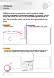
UTS Series Overview SOURIAU is pleased to announce the arrival of a brand new catalog containing some significant improvements to simplify the connector selection process and provide easy access to key information. In this version you can see all layouts at a glance, download 2D drawings and 3D models. Then, when your choice is made, you can click on the part number and buy online. Step 1 Step 2 Interactive zones. Clearer understanding of the range.
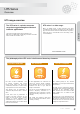
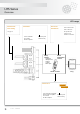
UTS Series Overview UTS range overview The bayonet coupling system makes it simple to use. With only a 1/3 twist of the coupling ring, connectors are mated with an audible and sensitive “click”. UTS series is a wide range... Based on multiple power & signal connectors and offers everything from box mounted receptacles and cable mounted plugs to cable mounted in-line and PCB mounted receptacles. Almost all ways to accommodate wires exist: Crimp, Solder, Screw termination.
UTS Series Overview UTS range UTS discrete wire sealing UTS Series UTS screw termination See page 9 Just screw the wires to the connector ! No special tools required, use a standard screwdriver Sealed: IP68/69K UV resistant UL/IEC compliant Corrosion-proof Plastic housing Crimp contact • machined • stamped and formed • coaxial • fibre optics Screw termination contact Plug Solder contact UTS Hi seal Sealed unmated: IP68/69K MIL-C-26482 compatible UV resistant UL/IEC compliant 8 © 2011 – SOURIA
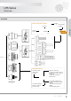
UTS Series Overview overview Backnut or Grommet No filler plug needed Containment ring Easy handling backshell Overview UTS discrete wire sealing Double Sealing UTS PCB contacts Stand-offs to allow cleaning after soldering Receptacle Low profile housing to limit space between panel and PCB Metal hold down clips - to lock the connector easily on the PCB and to release stress on solder joints - suitable for soldering in a metalised hole Pre-assembled PCB contacts - machined or stamped versions avai
UTS Series Overview General technical Mechanical • Durability: 250 matings & unmatings per MIL-C-26482 1 • Vibration resistance (all UTS versions except UTS Screw termination contacts): Sinusoidal vibrations per CEI 60512-4 - from 10 to 2000 Hz • Thermal shock: 5 cycles 30 min.
UTS Series Overview characteristics Overview Electrical • See each layout page 2 Material • Body connector + Backshell: Thermoplastic • Insert: - UTS Standard, UTS Discrete wire sealing, UTS Screw termination contacts: Thermoplastic - UTS Hi seal handsolder & UTS Hi seal with PC tails contacts: Elastomer 1 • Contacts: See page 140 • Nut: Metal 4 • Halogen free • RoHS compliant & conform to the Chinese standard SJ/T1166-2006 (Chinese RoHS equivalent) 5 • In accordance with: - UL 1977: Certificat E
UTS Series Mechanics Cable assembly 2 contacts 8E2/8D2: 12E2/12D2: ................................................................................................. 14 7A 16A 32V ............................................................................................. 20 150V ............................................................................................ 24 16A 40A 300V ............................................................................................ 28 300V ..............
UTS Series Mechanics Cable assembly Souriau provides connectors in various applications for more than 90 years in the most extreme environment. Being conscious about the difficulty to find a quick and a reliable harness manufacturer, we decided years ago to start in house cable assembly production. It allows customers to reduce the number of suppliers, and to take advantage of the "best in class" quality of the Souriau group.
UTS Series Mechanics Overmolding description Thermoplastic insert O ring Overmolding adapter Mechanics Compound PVC or PUR overmolding Discrete connector If cable jacket is breached... ...water ingress unhampered, leading to damage. Overmoulded connector If cable jacket is breached... ...prevents water ingress via capillary action.
UTS Series Mechanics Harnesses Overmoulded harnesses, straight ending Connector type Voltage Current UL Current IEC Harmonised cable part number* Male Female 2+PE 600 V 44 A 40 A HO5 VV - F 3Gg10 HAUTS0V142G1PST100 HAUTS0V142G1SST100 2+PE 500 V 10 A 16 A HO5 VV - F 3x1.5 HAUTS0V103PST100 HAUTS0V103SST100 3+PE 500 V 10 A 16 A HO5 VV - F 3G1.5 HAUTS0V103PEPST100 HAUTS0V103PESST100 3+PE 250 V 24 A 32 A HO5 VV - F 40G0.
UTS Series Mechanics Harnesses Overmoulded harnesses, right angle ending Part number (length: 1m.) Number of ways Voltage Current UL Current IEC Harmonised cable part number* Male Female 2+PE 600 V 44 A 40 A HO5 VV - F 3Gg10 HAUTS0V142G1PRA100 HAUTS0V142G1SRA100 2+PE 500 V 10 A 16 A HO5 VV - F 3x1.5 HAUTS0V103PRA100 HAUTS0V103SRA100 3+PE 500 V 10 A 16 A HO5 VV - F 3G1.5 HAUTS0V183G1PRA100 HAUTS0V183G1SRA100 3+PE 250 V 24 A 32 A HO5 VV - F 40G0.
UTS Series Mechanics Cable information Range of temperature: Occasional flexing: -5°C up to +70°C Fixed installation: -40°C up to +80°C Rated voltage: U0/U: 300/500 V Wire section : Arrangement with #16 contact: wire section 1.5 mm² Arrangement with #20 contact: wire section 0.5 mm² Harmonized reference: H05 VVF XX Standardization of European cable - DIN VDE 0281/DIN VDE 0282/DIN VDE 0292 Harmonized wire coding system 1 2 3 4 5 6 7 8 9 1. Basic type 2. Working voltage 3. Insulating 4.
UTS Series Mechanics Standardization of American cable Nomenclature Key S: J: V: P: E: O: T: W: H: VW-1: FT2: Service Grade (also means extra hard service when not followed by J, V, or P) Hard Service Vacuum cleaner cord (also light duty cable) Parallel cord (also known as zip cord) – Always light duty Thermoplastic Elastomer (UL/NEC designation ONLY) Oil Resistant* Thermoplastic Outdoor-includes sunlight resistant jacket and wet location rated conductors (formerly "W-A") Heater cable Flame retardant Flam
UTS Series 8E2/8D2 Layout OR OR WITH Specifications Contact type Handsolder electrical contacts loaded PCB contacts loaded Connector type Backshell Square flange receptacle Plug Part number Male insert Female insert Without (Fig.1) UTS08E2P UTS08E2S Without (Fig.6) UTS68E2P UTS68E2S Cable gland (Fig.7) UTS6JC8E2P UTS6JC8E2S Jam nut receptacle Without (Fig.3) UTS78E2P UTS78E2S Square flange receptacle Without (Fig.
UTS Series 8E2/8D2 2 contacts 7A/32V per IEC 61984 Dimensions Square flange receptacle - UTS0 11.7 7.5 20.7 7.8 Ø12 Ø12 7.5 15.3 11.7 2.4 Ø3.2 2.4 Fig. 1 Front view Fig. 2 Jam nut receptacle - UTS7 3.4 18 3.4 Ø12 24.2 18 Ø12 Ø12 18 3.5 3.5 Fig. 3 3.5 Fig. 4 Front view Fig. 5 Plug - UTS6 25.3 24.2 4.2 Mechanics 3.4 Mated connector length Fig. 6 61.1 Ø22.5 UTS0 UTS7 54 66.6 Fig.
UTS Series 8E2/8D2 Accessories Jam nut sealing caps Metal terminal Part number UTS8DCG Part number Part number UTS8DCGR UTS8DCGE UTS68C Part numbers Part numbers / neoprene 85005585A 85005594 IP40 Part number Gasket Plug cap Plug protective cap Metal terminal Plastic protective cap Receptacle cap Square flange sealing cap UTFD11B Electrical characteristics UTS 8E2/8D2 derating curves Current (A) 18 UL 7A 250V UL94 HB CSA 7A 250V UL94 HB 16 Test conditions 14 12 10 Contact used:
UTS Series Mechanics 8E2/8D2 © 2011 – SOURIAU 23
UTS Series 12E2/12D2 Layout OR OR WITH Specifications Contact type Handsolder electrical contacts loaded Connector type Backshell Square flange receptacle Plug Part number Male insert Female insert Without (Fig.1) UTS012E2P UTS012E2S Without (Fig.6) UTS612E2P UTS612E2S Cable gland (Fig.7) UTS6JC12E2P UTS6JC12E2S Jam nut receptacle Without (Fig.3) UTS712E2P UTS712E2S Square flange receptacle Without (Fig.
UTS Series 12E2/12D2 2 contacts 16A/150V per IEC 61984 Dimensions Square flange receptacle - UTS0 11.7 11.7 7.8 26.4 20.8 7.5 Ø19 Ø19 7.5 2.4 Ø3.2 2.4 Fig. 1 Front view Fig. 2 Jam nut receptacle - UTS7 3 3 31.9 Ø19 3.5 3.5 Fig. 3 3.5 Fig. 4 Front view Fig. 5 Plug - UTS6 25.3 27.2 4.2 18 Ø19 18 Ø19 18 Mechanics 3 Mated connector length Fig. 6 75.3 Ø30.1 UTS0 UTS7 66.7 81.7 Fig.
UTS Series 12E2/12D2 Accessories Jam nut sealing caps Plug sealing cap Square flange sealing cap Metal terminal Part number UTS12DCG Metal terminal Part number Part number Part number UTS12DCGR UTS612DCG UTS12DCGE Plastic protective cap Gasket Color coding rings Part numbers G for Green Receptacles Plugs UTS712CCRR UTS612CCRR Y for Yellow Part numbers Receptacle cap Plug cap 85005587A 85005596 UTS712CCRY UTS612CCRY R for Red Part numbers / neoprene UTS712CCRG UTS612CCRG * Add G for
UTS Series Mechanics 12E2/12D2 © 2011 – SOURIAU 27
UTS Series 103 Layout OR OR WITH Specifications Contact type Crimp contacts supply separately see page 31 PCB contacts supply separately see page 31 28 © 2011 – SOURIAU Connector type Backshell Free hanging receptacle Plug Jam nut receptacle Part number Male insert Female insert Cable gland (Fig.1) UTS1JC103P UTS1JC103S Without (Fig.2) UTS6103P UTS6103S Cable gland (Fig.3) UTS6JC103P UTS6JC103S Without (Fig.
UTS Series 103 2 + ground 16A/300V per IEC 61984 Dimensions Free hanging - UTS1 Ø15.1 70 Fig. 1 Plug - UTS6 63.2 Mechanics 33 Ø26.2 Ø26.2 Male Female 25.3 Fig. 2 Fig. 3 Jam nut receptacle - UTS7 Mated connector length - UTS7 27.2 Ø15.1 18.3 12.3 77.3 3.5 22.5 Fig. 4 Panel cut out Drilling pattern 1.5 16.7 3 Jam nut receptacle - UTS7 17.9 2.6 2.
UTS Series 103 Accessories and tooling Jam nut sealing caps Handle Tool kit Metal terminal Part number Part number Part number Part number UTS10DCG UTS10DCGR SHANDLES TOOLKIT Crimp tooling Plug sealing cap Part number UTS610DCG Contacts Plastic protective cap Gasket Contact size RM/RC 28M1K(1) S16RCM20 RM/RC 24M9K(1) S16RCM20 RM/RC 20M13K(1) S16RCM20 (1) S16RCM20 RM/RC 20M12K RM/RC 16M23K(1) RM/RC 14M50K(1) RM/RC 14M30K(1) Part numbers Receptacle cap Plug cap 85005586A 8500559
UTS Series 103 2 + ground 16A/300V per IEC 61984 Contacts Contact type Crimp Machined Stamped & formed reeled contacts AWG PCB Max wire Ø Max insulator Ø 0.55 1.1 RM28M1K(1) RC28M1K(1) 26-24 (1) (1) RM24M9K RC24M9K 0.8 1.6 22-20 RM20M13K(1) RC20M13K(1) 1.18 1.8 22-20 RM20M12K(1) RC20M12K(1) 1.18 2.2 20-16 RM16M23K(1) RC16M23K(1) 1.8 3.2 (1) (1) 16-14 RM14M50K RC14M50K 2.05 3.2 16-14 RM14M30K(1) RC14M30K(1) 2.28 3.2 26-24 SM24M1TK6(1)(2) SC24M1TK6(1)(2) 0.
UTS Series 142G1 Layout OR OR WITH Specifications Contact type Crimp contacts supply separately see page 35 32 © 2011 – SOURIAU Connector type Backshell Free hanging receptacle Plug Part number Male insert Female insert Cable gland (Fig.1) UTS1JC142G1P UTS1JC142G1S Without (Fig.3) UTS6142G1P UTS6142G1S Cable gland (Fig.4) UTS6JC142G1P UTS6JC142G1S Jam nut receptacle Without (Fig.2) UTS7142G1P UTS7142G1S NPT threaded receptacle Without (Fig.
UTS Series 142G1 2 + ground 40A/300V per IEC 61984 Dimensions Free hanging - UTS1 Jam nut receptacle - UTS7 70 1.6 35.1 Ø31.5 Ø22.3 18 3.5 30.4 Fig. 1 Fig. 2 Plug - UTS6 70 Mechanics 33 Ø31.5 Ø35.1 Male Female 25.3 Fig. 3 Fig. 4 NPT threaded receptacle - UTS7 25.4 25.4 Ø22.3 35.3 23.1 Fig. 5 Panel cut out Drilling pattern 2.1 24.5 4.2 Jam nut receptacle - UTS7 25.9 3.6 3.
UTS Series 142G1 Accessories and tooling Jam nut sealing caps Hand tool Metal terminal Part number Part number UTS14DCG UTS14DCGR Part number M317 Plug sealing cap Positioner + locator setting Part number UTS614DCG Plastic protective cap Gasket Part number VGE10078A Extraction tool Part numbers Receptacle cap Plug cap 85005588A 85005597 Part numbers / neoprene UTFD14B Color coding rings Part number Part numbers G for Green Receptacles Plugs UTS714CCRR UTS614CCRR Y for Yellow UTS71
UTS Series 142G1 2 + ground 40A/300V per IEC 61984 Contacts Crimp #8 Contact type Machined AWG Part number Male Max wire Ø Female 16 82913601A(1) 82913600A(1) - 14 (1) 82913603A (1) 82913602A - 12 82913605A(1) 82913604A(1) - 10 (1) 82913607A (1) 82913606A - 82913609A(1) 82913608A(1) - 8 Max insulator Ø 6.
UTS Series 8E3/8D3 Layout OR OR WITH Specifications Contact type Handsolder electrical contacts loaded Connector type Backshell Square flange receptacle Plug Part number Male insert Female insert Without (Fig.1) UTS08E3P UTS08E3S Without (Fig.6) UTS68E3P UTS68E3S Cable gland (Fig.7) UTS6JC8E3P UTS6JC8E3S Jam nut receptacle Without (Fig.3) UTS78E3P UTS78E3S Square flange receptacle Without (Fig.
UTS Series 8E3/8D3 3 contacts 7A/32V per IEC 61984 Dimensions Square flange receptacle - UTS0 7.5 11.7 20.7 7.8 15.3 7.5 Ø12 Ø12 11.7 2.4 Ø3.2 2.4 Fig. 1 Front view Fig. 2 Jam nut receptacle - UTS7 3.4 24.2 4.2 Ø12 24.2 18 Ø12 18 Ø12 18 3.4 3.5 3.5 Fig. 3 Mechanics 3.4 3.5 Fig. 4 Front view Fig. 5 Plug - UTS6 Mated connector length Fig. 6 61.1 25.3 Ø22.5 UTS0 UTS7 66.6 54 Fig.
UTS Series 8E3/8D3 Accessories Jam nut sealing caps Metal terminal Part number UTS8DCG Part number Part number UTS8DCGR UTS8DCGE UTS68C Part numbers Part numbers / neoprene 85005585A 85005594 IP40 Part number Gasket Plug cap Plug protective cap Metal terminal Plastic protective cap Receptacle cap Square flange sealing cap UTFD11B Electrical characteristics UTS 8E3/8D3 derating curves Current (A) 18 UL 7A 250V UL94 HB CSA 7A 250V UL94 HB 16 14 Test conditions Contact used: Machine
UTS Series Mechanics 8E3/8D3 © 2011 – SOURIAU 39
UTS Series 8E3A/8E98 - 8D3A/8D98 Layout OR OR WITH Specifications Contact type Connector type Square flange receptacle Backshell Without (Fig.1) Without (Fig.6) Handsolder electrical contacts loaded Plug Cable gland (Fig.7) Jam nut receptacle Square flange receptacle Without (Fig.3) Without (Fig.2) Jam nut receptacle with stand off and with hold down clips Without (Fig.5) Jam nut receptacle with stand off and without hold down clip Without (Fig.
UTS Series 8E3A/8E98 - 8D3A/8D98 3 contacts 7A/50V per IEC 61984 Dimensions Square flange receptacle - UTS0 7.5 11.7 7.8 20.7 Ø12 Ø12 7.5 15.3 11.7 2.4 Ø3.2 2.4 Fig. 1 Front view Fig. 2 Jam nut receptacle - UTS7 3 3 24.2 Ø12 3.5 3.5 Fig. 3 3.5 Fig. 4 Front view Fig. 5 Plug - UTS6 25.3 24.2 4.2 18 Ø12 18 Ø12 18 Mechanics 3 Mated connector length Fig. 6 61.1 Ø22.5 UTS0 UTS7 54 66.6 Fig.
UTS Series 8E3A/8E98 - 8D3A/8D98 Accessories Jam nut sealing caps Metal terminal Part number UTS8DCG Part number Part number UTS8DCGR UTS8DCGE UTS68C Part numbers Part numbers / neoprene 85005585A 85005594 IP40 Part number Gasket Plug cap Plug protective cap Metal terminal Plastic protective cap Receptacle cap Square flange sealing cap UTFD11B Electrical characteristics UTS 8E3A/98 - 8D3A/98 derating curves Current (A) 18 16 UL 7A 250V UL94 HB CSA 7A 250V UL94 HB 14 Test conditio
UTS Series Mechanics 8E3A/8E98 - 8D3A/8D98 © 2011 – SOURIAU 43
UTS Series 8E33/8D33 Layout OR OR WITH Specifications Contact type Handsolder electrical contacts loaded Connector type Backshell Square flange receptacle Plug Part number Male insert Female insert Without (Fig.1) UTS08E33P UTS08E33S Without (Fig.6) UTS68E33P UTS68E33S Cable gland (Fig.7) UTS6JC8E33P UTS6JC8E33S Jam nut receptacle Without (Fig.3) UTS78E33P UTS78E33S Square flange receptacle Without (Fig.
UTS Series 8E33/8D33 3 contacts 7A/50V per IEC 61984 Dimensions Square flange receptacle - UTS0 7.5 11.7 20.7 7.8 15.3 7.5 Ø12 Ø12 11.7 2.4 Ø3.2 2.4 Fig. 1 Front view Fig. 2 Jam nut receptacle - UTS7 3.4 24.2 3.4 4.2 Ø12 24.2 18 Ø12 18 Ø12 18 3.5 3.5 Fig. 3 Mechanics 3.4 3.5 Fig. 4 Front view Fig. 5 Plug - UTS6 Mated connector length Fig. 6 61.1 25.3 Ø22.5 UTS0 UTS7 66.6 54 Fig.
UTS Series 8E33/8D33 Accessories Jam nut sealing caps Metal terminal Part number UTS8DCG Part number Part number UTS8DCGR UTS8DCGE UTS68C Part numbers Part numbers / neoprene 85005585A 85005594 IP40 Part number Gasket Plug cap Plug protective cap Metal terminal Plastic protective cap Receptacle cap Square flange sealing cap UTFD11B Electrical characteristics UTS 8E33/8D33 de-rating curves Current (A) 18 16 UL 7A 250V UL94 HB CSA 7A 250V UL94 HB 14 Test conditions Contact used: Ma
UTS Series Mechanics 8E33/8D33 © 2011 – SOURIAU 47
UTS Series 12E3/12D3 Layout OR OR WITH Specifications Contact type Handsolder electrical contacts loaded Connector type Backshell Square flange receptacle Plug Part number Male insert Female insert Without (Fig.6) UTS012E3P UTS012E3S Without (Fig.1) UTS612E3P UTS612E3S Cable gland (Fig.2) UTS6JC12E3P UTS6JC12E3S Jam nut receptacle Without (Fig.3) UTS712E3P UTS712E3S Square flange receptacle Without (Fig.
UTS Series 12E3/12D3 3 contacts 16A/150V per IEC 61984 Dimensions Plug - UTS6 25.3 Ø30.1 Ø30.1 66.7 Fig. 1 Fig. 2 Jam nut receptacle - UTS7 3 4.2 Ø19 31.9 18 Ø19 18 Ø19 18 27.2 3 3.5 Fig. 3 3.5 Fig. 4 3.5 Fig. 5 Square flange receptacle - UTS0 Fig. 7 11.7 7.5 Mechanics 3 Front view Mated connector length 26.4 75.3 UTS0 Ø19 20.8 7 7.8 UTS7 81.7 2.4 Ø3.2 Front view Fig. 6 Panel cut out Square flange receptacle - UTS0 Drilling pattern 22° Ø3.1 Jam nut receptacle - UTS7 Ø3.
UTS Series 12E3/12D3 Accessories Jam nut sealing caps Plug sealing cap Square flange sealing cap Metal terminal Part number UTS12DCG Metal terminal Part number Part number Part number UTS12DCGR UTS612DCG UTS12DCGE Plastic protective cap Gasket Color coding rings Part numbers G for Green Receptacles Plugs UTS712CCRR UTS612CCRR Y for Yellow Part numbers Receptacle cap Plug cap 85005587A 85005596 UTS712CCRY UTS612CCRY R for Red Part numbers / neoprene UTS712CCRG UTS612CCRG * Add G for
UTS Series Mechanics 12E3/12D3 © 2011 – SOURIAU 51
UTS Series 124 - 12E4/12D4 Layout y OR OR OR WITH Specifications Contact type Crimp contacts supply separately see page 55 Backshell Square flange receptacle Without (Fig.1) UTS0124P Jam nut receptacle Without (Fig.5) UTS7124P UTS7124S Free hanging receptacle Cable gland (Fig.13) UTS1JC124P UTS1JC124S Female insert Without (Fig.11) UTS6124P UTS6124S UTS6JC124P UTS6JC124S Square flange receptacle Without (Fig.3) UTS012E4P UTS012E4S Jam nut receptacle Without (Fig.
UTS Series 124 - 12E4/12D4 3 + ground 16A/300V per IEC 61984 Dimensions Square flange receptacle - UTS0 Fig. 2 11.7 7.5 11.7 7.5 26.4 7.5 11.7 7.8 20.8 Ø19 Ø19 Ø19 9.1 4 2.4 2.4 Fig. 1 2.4 Fig. 3 Ø3.2 Front view Fig. 4 Jam nut receptacle - UTS7 Fig. 7 2.4 Fig. 9 18 2.4 18 31.9 Hold down clip Ø19 Ø19 Ø19 Male 27.2 4.2 Female 3.5 3.5 Fig. 6 3.5 Fig. 8 Front view Fig. 10 Free hanging - UTS1 / Plug - UTS6 Fig. 11 3 Mated connector length Fig. 12 25.3 75.3 66.7 Ø30.
UTS Series 124 - 12E4/12D4 Accessories and tooling Jam nut sealing caps Handle Tool kit Metal terminal Part number Part number Part number Part number UTS12DCG UTS12DCGR SHANDLES TOOLKIT Crimp tooling Plug sealing cap Square flange sealing cap Metal terminal Part number Part number UTS612DCG UTS12DCGE Contacts Plastic protective cap Gasket Contact size RM/RC 28M1K(1) S16RCM20 RM/RC 24M9K(1) S16RCM20 RM/RC 20M13K(1) S16RCM20 (1) S16RCM20 RM/RC 20M12K RM/RC 16M23K(1) RM/RC 14M5
UTS Series 124 - 12E4/12D4 3 + ground 16A/300V per IEC 61984 Contacts Contact type Crimp Machined Stamped & formed reeled contacts AWG PCB Max wire Ø Max insulator Ø 0.55 1.1 RM28M1K(1) RC28M1K(1) 26-24 (1) (1) RM24M9K RC24M9K 0.8 1.6 22-20 RM20M13K(1) RC20M13K(1) 1.18 1.8 22-20 RM20M12K(1) RC20M12K(1) 1.18 2.2 20-16 RM16M23K(1) RC16M23K(1) 1.8 3.2 (1) (1) 16-14 RM14M50K RC14M50K 2.05 3.2 16-14 RM14M30K(1) RC14M30K(1) 2.28 3.
UTS Series 183G1 Layout ayout WITH Specifications Contact type Crimp contacts supply separately see page 59 56 © 2011 – SOURIAU Part number Connector type Backshell NPT threaded receptacle Without (Fig.1) Plug Without (Fig.2) UTS6183G1P Plug Cable gland (Fig.
UTS Series 183G1 3 + ground 32A/300V per IEC 61984 Dimensions NPT threaded receptacle - UTS7 14.5 31.8 Ø28.6 Ø19.6 17.3 NPT - 3/4˝ Fig. 1 Plug - UTS6 Ø42 Mechanics 81.3 Ø42 37.5 Fig. 2 Fig. 3 Mated connector length - UTS6JC 90.5 Drilling pattern 5.1 5.1 5.1 5.
UTS Series 183G1 Accessories and tooling Jam nut sealing caps Hand tool Metal terminal Part number Part number UTS14DCG UTS14DCGR Part number M317 Plug sealing cap Positioner + locator setting Part number UTS614DCG Plastic protective cap Gasket Part number VGE10078A Extraction tool Part numbers Receptacle cap Plug cap 85005588A 85005597 Part numbers / neoprene UTFD14B Color coding rings Part number Part numbers G for Green Receptacles Plugs UTS714CCRR UTS614CCRR Y for Yellow UTS71
UTS Series 183G1 3 + ground 32A/300V per IEC 61984 Contacts Crimp #8 Contact type Machined AWG Part number Male Max wire Ø Female 16 82913601A(1) 82913600A(1) - 14 82913603A (1) (1) - 12 82913605A(1) 82913604A(1) - 10 (1) (1) - 82913608A(1) - 8 82913607A 82913602A 82913606A 82913609A(1) Max insulator Ø 6.
UTS Series 8E4/8D4 Layout OR OR WITH Specifications Contact type Handsolder electrical contacts loaded Connector type Backshell Square flange receptacle Plug Part number Male insert Female insert Without (Fig.1) UTS08E4P UTS08E4S Without (Fig.6) UTS68E4P UTS68E4S Cable gland (Fig.7) UTS6JC8E4P UTS6JC8E4S Jam nut receptacle Without (Fig.3) UTS78E4P UTS78E4S Square flange receptacle Without (Fig.
UTS Series 8E4/8D4 4 contacts 7A/32V per IEC 61984 Dimensions Square flange receptacle - UTS0 11.7 7.5 20.7 7.8 Ø12 Ø12 7.5 15.3 11.7 2.4 Ø3.2 2.4 Fig. 1 Front view Fig. 2 Jam nut receptacle - UTS7 3.4 24.2 Ø12 3.5 3.5 Fig. 3 3.5 Fig. 4 Front view Fig. 5 Plug - UTS6 25.3 24.2 4.2 18 Ø12 18 Ø12 18 3.4 Mechanics 3.4 Mated connector length Fig. 6 61.1 Ø22.5 UTS0 UTS7 54 66.6 Fig.
UTS Series 8E4/8D4 Accessories Jam nut sealing caps Metal terminal Part number UTS8DCG Part number Part number UTS8DCGR UTS8DCGE UTS68C Part numbers Part numbers / neoprene 85005585A 85005594 IP40 Part number Gasket Plug cap Plug protective cap Metal terminal Plastic protective cap Receptacle cap Square flange sealing cap UTFD11B Electrical characteristics UTS 8E4/8D4 derating curves Current (A) 18 16 UL 7A 250V UL94 HB CSA 7A 250V UL94 HB 14 Test conditions Contact used: Machine
UTS Series Mechanics 8E4/8D4 © 2011 – SOURIAU 63
UTS Series 102W2 (2x#12 + 2x#20) Layout y WITH Specifications Contact type Crimp contacts supply separately see page 67 64 © 2011 – SOURIAU Connector type Backshell Free hanging receptacle Part number Male insert Female insert Cable gland (Fig.1) UTS1JC102W2P UTS1JC102W2S Plug Without (Fig.2) UTS6102W2P UTS6102W2S Plug Cable gland (Fig.3) UTS6JC102W2P UTS6JC102W2S Jam nut receptacle Without (Fig.
UTS Series 102W2 (2x#12 + 2x#20) 4 contacts 25A/150V per IEC 61984 Dimensions Free hanging - UTS1 Ø15.1 70 Fig. 1 Plug - UTS6 25.3 Fig. 2 Female Jam nut receptacle - UTS7 2.4 Fig. 3 Mated connector length - UTS7 27.2 Ø15.1 18.3 Mechanics Ø26.2 Ø26.2 Fig. 2 Male 63.2 Ø26.2 33 3.5 77.3 22.5 Fig. 4 Panel cut out Drilling pattern 3 16.7 3 Jam nut receptacle - UTS7 17.
UTS Series 102W2 (2x#12 + 2x#20) Accessories and tooling Jam nut sealing caps Crimp tooling #20 Metal terminal Part number Part number Part number Part number UTS10DCG UTS10DCGR SHANDLES TOOLKIT Plug sealing cap Contacts Part number RM/RC 24W3K(1) UTS610DCG (1) RM/RC 20W3K RM/RC 18W3K(1) S20RM S20RM Standard contacts SM/SC 24W3S(2) SM/SC 24WL3S(3) Plastic protective cap Gasket Part number of head Contact size S20RM S20SCM20 #20 Ø 1mm S20SCM20 SM/SC 20W3S(2) S20SCM20 SM/SC 20WL3
UTS Series 102W2 (2x#12 + 2x#20) 4 contacts 25A/150V per IEC 61984 Contacts #20 Contact type Crimp Machined PCB stamped & formed reeled contacts Machined (3) AWG Part number Max insulator Ø Male Female 26-24 RM24W3K(1) RC24W3K(1) 1.58 22-20 RM20W3K(1) RC20W3K(1) 1.58 20-18 (1) (1) RM18W3K RC18W3K 2.1 26-24 SM24W3TK6(2) SC24W3TK6(2) 0.89-1.58 26-24 SM24W3S26 (2) (2) 0.89-1.58 22-20 SM20W3TK6(2) SC20W3TK6(2) 1.17-2.08 22-20 (2) (2) 1.17-2.
UTS Series 104 Layout y OR OR OR OR WITH Specifications Contact type Crimp contact supply separately see next page 71 68 © 2011 – SOURIAU Connector type Backshell Square flange receptacle Part number Male insert Female insert Without (Fig.1) UTS0104P UTS0104S Free hanging receptacle Cable gland and grommet (Fig.2) UTS1GJC104P Free hanging receptacle Nut and grommet (Fig.3) UTS1GN104P Free hanging receptacle Cable gland (Fig.2) UTS1JC104P UTS1JC104S Plug Without (Fig.
UTS Series 104 4 contacts 13A/150V per IEC 61984 Dimensions Square flange receptacle - UTS0 Fig. 2 24 20.8 2.4 70 Ø15.1 10.5 Ø15.1 11.5 Free hanging - UTS1 Ø3.2 Fig. 1 40.9 Front view Fig. 3 Plug - UTS6 63.2 32.5 Mechanics 33 Ø26.2 Ø26.2 Ø26.2 Male Female 25.3 Fig. 4 Fig. 5 Fig. 6 Jam nut receptacle - UTS7 18.3 41 2.4 Mated connector length Fig. 8 70.9 18.3 Ø15.1 Ø15.1 UTS0 UTS7 3.5 3.5 Fig. 7 77.3 70.7 Fig.
UTS Series 104 Accessories and tooling Jam nut sealing caps Handle Tool kit Metal terminal Part number Part number Part number Part number UTS10DCG UTS10DCGR SHANDLES TOOLKIT Crimp tooling Plug sealing cap Square flange sealing cap Metal terminal Part number Part number UTS610DCG UTS10DCGE Contacts Plastic protective cap Gasket Contact size RM/RC 28M1K(1) S16RCM20 RM/RC 24M9K(1) S16RCM20 RM/RC 20M13K(1) S16RCM20 (1) S16RCM20 RM/RC 20M12K RM/RC 16M23K(1) RM/RC 14M50K(1) RM/RC
UTS Series 104 4 contacts 13A/150V per IEC 61984 Contacts Contact type Crimp Machined Stamped & formed reeled contacts AWG PCB Max wire Ø Max insulator Ø 0.55 1.1 RM28M1K(1) RC28M1K(1) 26-24 (1) (1) RM24M9K RC24M9K 0.8 1.6 22-20 RM20M13K(1) RC20M13K(1) 1.18 1.8 22-20 RM20M12K(1) RC20M12K(1) 1.18 2.2 20-16 RM16M23K(1) RC16M23K(1) 1.8 3.2 (1) (1) 16-14 RM14M50K RC14M50K 2.05 3.2 16-14 RM14M30K(1) RC14M30K(1) 2.28 3.2 26-24 SM24M1TK6(1)(2) SC24M1TK6(1)(2) 0.
UTS Series 14E5/14D5 Layout y OR OR WITH Specifications Contact type Handsolder electrical contacts loaded Connector type Backshell Square flange receptacle Plug Part number Male insert Female insert Without (Fig.6) UTS014E5P UTS014E5S Without (Fig.1) UTS614E5P UTS614E5S Cable gland (Fig.2) UTS6JC14E5P UTS6JC14E5S Jam nut receptacle Without (Fig.3) UTS714E5P UTS714E5S Square flange receptacle Without (Fig.
UTS Series 14E5/14D5 5 contacts 16A/150V per IEC 61984 Dimensions Plug - UTS6 25.3 Ø35.1 Ø35.1 70 Fig. 1 Fig. 2 Jam nut receptacle - UTS7 3 3 4.2 30.4 18 3.5 35.1 Ø22.3 Ø22.3 Ø22.3 18 3.5 Fig. 3 Mechanics 3 18 3.5 Fig. 4 Front view Fig. 5 Square flange receptacle - UTS0 Mated connector length 28.8 7.5 11.3 75 7.8 23.2 Ø22.3 UTS0 UTS7 2.3 82 Ø3.2 Fig. 6 Front view Panel cut out Square flange receptacle - UTS0 Drilling pattern Jam nut receptacle - UTS7 22° Ø3.1 Ø3.
UTS Series 14E5/14D5 Accessories Jam nut sealing caps Plug sealing cap Square flange sealing cap Metal terminal Part number UTS14DCG Metal terminal Part number Part number Part number UTS14DCGR UTS614DCG UTS14DCGE Plastic protective cap Gasket Color coding rings Part numbers G for Green Receptacles Plugs UTS714CCRR UTS614CCRR Y for Yellow Part numbers Receptacle cap Plug cap 85005588A 85005597 UTS714CCRY UTS614CCRY R for Red UTS714CCRG UTS614CCRG Part numbers / neoprene * Add G fo
UTS Series Mechanics 14E5/14D5 © 2011 – SOURIAU 75
UTS Series 103W3 (3x#16 + 3x#20) Layout y OR OR WITH Specifications Contact type 76 Backshell Free hanging receptacle Part number Male insert Female insert Cable gland (Fig.1) UTS1JC103W3P UTS1JC103W3S Plug Without (Fig.2) UTS6103W3P UTS6103W3S Plug Cable gland (Fig.3) UTS6JC103W3P UTS6JC103W3S Jam nut receptacle Without (Fig.4) UTS7103W3P UTS7103W3S Jam nut receptacle with stand off and without hold down clip Without (Fig.
UTS Series 103W3 (3x#16 + 3x#20) 6 contacts 5A/32V per IEC 61984 Dimensions Free hanging - UTS1 Ø15.1 70 Fig. 1 Plug - UTS6 25.3 Fig. 2 Male Mechanics Fig. 2 Female Jam nut receptacle - UTS7 2.4 Fig. 3 Mated connector length - UTS7 27.2 Ø15.1 18.3 63.2 Ø26.2 Ø26.2 Ø26.2 33 77.3 3.5 22.5 Fig. 4 Drilling pattern 0.7 16.7 0.8 Jam nut receptacle - UTS7 2.5 Panel cut out 17.9 3 2.
UTS Series 103W3 (3x#16 + 3x#20) Accessories and tooling Jam nut sealing caps Handle Tool kit Metal terminal Part number Part number Part number Part number UTS10DCG UTS10DCGR SHANDLES TOOLKIT Crimp tooling Plug sealing cap Square flange sealing cap Contacts Metal terminal Part number Part number UTS610DCG UTS10DCGE Plastic protective cap Part numbers Receptacle cap Plug cap 85005586A 85005595 Gasket Part numbers / neoprene UTFD12B Color coding rings Part numbers G for Green Re
UTS Series 103W3 (3x#16 + 3x#20) 6 contacts 5A/32V per IEC 61984 Contacts Max insulator Ø 0.55 0.8 1.18 1.18 1.8 2.05 2.28 1.1 1.6 1.8 2.2 3.2 3.2 3.2 SC24M1TK6(1)(2) SC20M1TK6(1)(2) SC16M1TK6(1)(2) SC16M11TK6(1)(2) SC14M1TK6(1)(2) 0.89-1.28 1.17-2.08 3.0 2.0-3.0 3.
UTS Series 106 - 10E6/10D6 Layout y OR OR OR WITH Specifications Contact type Crimp contacts supply separately see page 83 Handsolder electrical contacts loaded Connector type Backshell Free hanging receptacle Cable gland (Fig.1) Part number Male insert Female insert UTS1JC106P UTS1JC106S Plug Without (Fig.2) UTS6106P UTS6106S Plug Cable gland (Fig.3) UTS6JC106P UTS6JC106S Jam nut receptacle Without (Fig.4) UTS7106P UTS7106S Square flange receptacle Without (Fig.
UTS Series 106 - 10E6/10D6 6 contacts 7A/32V per IEC 61984 Dimensions Free hanging - UTS1 Plug - UTS6 33 70 63.2 Ø26.2 Ø15.1 Ø26.2 Male Female 25.3 Fig. 1 Fig. 2 Fig. 3 Jam nut receptacle - UTS7 3 4.2 3.5 18.3 Ø15.1 Ø15.1 18.3 Ø15.1 18.3 3 3.5 Fig. 5 3.5 Fig. 6 11.7 Front view Fig. 7 Square flange receptacle - UTS0 Fig. 8 22.5 3 Mechanics 12.3 27.2 Fig. 4 Mated connector length 24 70.9 16.2 20.8 Ø15.1 UTS0 UTS7 7.5 77.3 2.3 Ø3.2 Fig.
UTS Series 106 - 10E6/10D6 Accessories and tooling Jam nut sealing caps Handle Tool kit Metal terminal Part number Part number Part number Part number UTS10DCG UTS10DCGR SHANDLES TOOLKIT Crimp tooling Plug sealing cap Square flange sealing cap Metal terminal Part number Part number UTS610DCG UTS10DCGE Contacts Plastic protective cap Gasket Contact size RM/RC 24W3K(1) S20RM RM/RC 20W3K(1) RM/RC 18W3K(1) SM/SC 24W3S S20RM Standard contacts (2) SM/SC 24WL3S(3) #20 Ø 1mm SM/SC 20W3
UTS Series 106 - 10E6/10D6 6 contacts 7A/32V per IEC 61984 Contacts #20 Contact type AWG Machined Crimp PCB Max wire Ø Max insulator Ø RM24W3K(1) RC24W3K(1) - 1.58 22-20 (1) RC20W3K(1) - 1.58 (1) (1) - 2.1 RM20W3K RM18W3K RC18W3K 26-24 SM24W3TK6(2) SC24W3TK6(2) - 0.89-1.58 26-24 SM24W3TK6(2) SC24W3TK6(2) - 0.89-1.58 22-20 (2) (2) - 1.17-2.08 (2) - 1.17-2.
UTS Series 10E98/10D98 Layout y OR OR WITH Specifications Contact type Handsolder electrical contacts loaded PCB contacts loaded Connector type Backshell Square flange receptacle Plug Part number Male insert Female insert Without (Fig.6) UTS010E98P UTS010E98S Without (Fig.1) UTS610E98P UTS610E98S Cable gland (Fig.2) UTS6JC10E98P UTS6JC10E98S Jam nut receptacle Without (Fig.3) UTS710E98P UTS710E98S Square flange receptacle Without (Fig.
UTS Series 10E98/10D98 6 contacts 7A/50V per IEC 61984 Dimensions Plug - UTS6 Ø26.2 70 Ø26.2 25.3 Fig. 1 Fig. 2 Jam nut receptacle - UTS7 3 3 18.3 27.2 Ø15.1 3.5 3.5 3.5 Fig. 3 Fig. 7 Front view Fig. 5 Fig. 4 Square flange receptacle - UTS0 18.3 22.4 Ø15.1 18.3 Ø15.1 18.3 4.2 Mechanics 3 Mated connector length 24 70.9 16.2 20.8 Ø15.1 UTS0 UTS7 7.5 77.3 2.3 Ø3.2 Front view Panel cut out Square flange receptacle - UTS0 Drilling pattern Jam nut receptacle - UTS7 22° Ø3.
UTS Series 10E98/10D98 Accessories Jam nut sealing caps Plug protective cap Square flange sealing cap Metal terminal Part number UTS10DCG Metal terminal Part number Part number Part number UTS10DCGR UTS610DCG UTS10DCGE Plastic protective cap Gasket Color coding rings Part numbers G for Green Receptacles Plugs UTS710CCRR UTS610CCRR Y for Yellow Part numbers UTS710CCRY UTS610CCRY R for Red UTS710CCRG UTS610CCRG Part numbers / neoprene Receptacle cap Plug cap 85005586A 85005595 * Ad
UTS Series Mechanics 10E98/10D98 © 2011 – SOURIAU 87
UTS Series 147 - 14E7/14D7 Layout y OR OR OR OR OR WITH Specifications Contact type Connector type Part number Backshell Male insert Crimp contacts supply separately see page 91 Without (Fig.2) UTS0147P Free hanging receptacle Cable gland and grommet (Fig.3) UTS1GJC147P Free hanging receptacle Nut and grommet (Fig.4) UTS1GN147P Free hanging receptacle Cable gland (Fig.3) UTS1JC147P UTS1JC147S Plug Without (Fig.5) UTS6147P UTS6147S Plug Cable gland and grommet (Fig.
UTS Series 147 - 14E7/14D7 6 + ground 16A/300V per IEC 61984 Dimensions Square flange receptacle - UTS0 Free hanging - UTS1 Fig. 1 Fig. 3 78.5 28.8 23.2 Ø22.3 29.1 Ø22.3 11.3 2.3 22 Ø3.2 Front view Fig. 2 43 Fig. 4 Plug - UTS6 70 32 Mechanics 33 Ø35.1 Ø35.1 Ø35.1 Male Female 23.5 Fig. 5 Fig. 6 Fig. 7 Jam nut receptacle - UTS7 Fig. 8 18 Fig. 9 49 1.6 75 18 Ø31.8 Ø22.3 UTS0 UTS7 4.2 3 3.5 Mated connector length 3.5 Fig. 11 82 70.7 Fig.
UTS Series 147 - 14E7/14D7 Accessories and tooling Jam nut sealing caps Handle Tool kit Metal terminal Part number Part number Part number Part number UTS14DCG UTS14DCGR SHANDLES TOOLKIT Crimp tooling Plug sealing cap Square flange sealing cap Metal terminal Part number Part number UTS614DCG UTS14DCGE Contacts Plastic protective cap Gasket Contact size RM/RC 28M1K(1) S16RCM20 RM/RC 24M9K(1) S16RCM20 RM/RC 20M13K(1) S16RCM20 (1) S16RCM20 RM/RC 20M12K RM/RC 16M23K(1) RM/RC 14M5
UTS Series 147 - 14E7/14D7 6 + ground 16A/300V per IEC 61984 Contacts Contact type Crimp Machined Stamped & formed reeled contacts AWG PCB Max wire Ø Max insulator Ø 0.55 1.1 RM28M1K(1) RC28M1K(1) 26-24 (1) (1) RM24M9K RC24M9K 0.8 1.6 22-20 RM20M13K(1) RC20M13K(1) 1.18 1.8 22-20 RM20M12K(1) RC20M12K(1) 1.18 2.2 20-16 RM16M23K(1) RC16M23K(1) 1.8 3.2 (1) (1) 16-14 RM14M50K RC14M50K 2.05 3.2 16-14 RM14M30K(1) RC14M30K(1) 2.28 3.
UTS Series 10E7/10D7 Layout OR OR WITH Specifications Contact type Handsolder electrical contacts loaded Connector type Backshell Square flange receptacle Plug Part number Male insert Female insert Without (Fig.6) UTS010E7P UTS010E7S Without (Fig.1) UTS610E7P UTS610E7S Cable gland (Fig.2) UTS6JC10E7P UTS6JC10E7S Jam nut receptacle Without (Fig.3) UTS710E7P UTS710E7S Square flange receptacle Without (Fig.
UTS Series 10E7/10D7 7 contacts 7A/50V per IEC 61984 Dimensions Plug - UTS6 70 Ø26.2 Ø26.2 25.3 Fig. 1 Fig. 2 Jam nut receptacle - UTS7 3 3 4.2 22.4 18.3 3.5 27.2 Ø15.1 Ø15.1 18.3 Ø15.1 18.3 3.5 Fig. 3 3.5 Fig. 7 Front view Fig. 5 Fig. 4 Square flange receptacle - UTS0 Mated connector length 24 16.2 11.7 Mechanics 3 70.9 20.8 Ø15.1 UTS0 UTS7 7.5 2.3 Fig. 6 77.3 Ø3.2 Front view Panel cut out Square flange receptacle - UTS0 Drilling pattern Jam nut receptacle - UTS7 Ø3.
UTS Series 10E7/10D7 Accessories Jam nut sealing caps Plug sealing cap Square flange sealing cap Metal terminal Part number UTS10DCG Metal terminal Part number Part number Part number UTS10DCGR UTS610DCG UTS10DCGE Plastic protective cap Gasket Color coding rings Part numbers G for Green Receptacles Plugs UTS710CCRR UTS610CCRR Y for Yellow Part numbers UTS710CCRY UTS610CCRY R for Red UTS710CCRG UTS610CCRG Part numbers / neoprene Receptacle cap Plug cap 85005586A 85005595 * Add G f
UTS Series Mechanics 10E7/10D7 © 2011 – SOURIAU 95
UTS Series 128 Layout OR OR OR OR OR WITH Specifications Contact type Crimp contacts supply separately see page 99 PCB contacts loaded 96 © 2011 – SOURIAU Connector type Backshell Square flange receptacle Part number Male insert Female insert Without (Fig.1) UTS0128P UTS0128S Free hanging receptacle Cable gland and grommet (Fig.2) UTS1GJC128P Free hanging receptacle Nut and grommet (Fig.3) UTS1GN128P Free hanging receptacle Cable gland (Fig.
UTS Series 128 8 contacts 10A/80V per IEC 61984 Dimensions Square flange receptacle - UTS0 Fig. 2 26.4 20.8 74.5 2.3 10.5 Ø19.1 18.1 Ø19.1 11.7 Free hanging - UTS1 Ø3.2 Fig. 1 40.9 Front view Fig. 3 Plug - UTS6 65.7 33 Mechanics 33 Ø30.1 Ø30.1 Ø30.1 Male Female 25.3 Fig. 4 Fig. 5 Fig. 6 Jam nut receptacle - UTS7 Fig. 8 18 Fig. 9 49.1 75.3 UTS0 18 Ø19.1 Ø19.1 1.6 Mated connector length UTS7 4.2 3 3.5 3.5 Fig. 11 81.7 74.5 Fig.
UTS Series 128 Accessories and tooling Jam nut sealing caps Handle Tool kit Metal terminal Part number Part number Part number Part number UTS12DCG UTS12DCGR SHANDLES TOOLKIT Crimp tooling Plug sealing cap Square flange sealing cap Metal terminal Part number Part number UTS612DCG UTS12DCGE Contacts Plastic protective cap Gasket Contact size RM/RC 28M1K(1) S16RCM20 RM/RC 24M9K(1) S16RCM20 RM/RC 20M13K(1) S16RCM20 (1) S16RCM20 RM/RC 20M12K RM/RC 16M23K(1) RM/RC 14M50K(1) RM/RC
UTS Series 128 8 contacts 10A/80V per IEC 61984 Contacts Contact type Crimp Machined Stamped & formed reeled contacts AWG PCB Max wire Ø Max insulator Ø 0.55 1.1 RM28M1K(1) RC28M1K(1) 26-24 (1) (1) RM24M9K RC24M9K 0.8 1.6 22-20 RM20M13K(1) RC20M13K(1) 1.18 1.8 22-20 RM20M12K(1) RC20M12K(1) 1.18 2.2 20-16 RM16M23K(1) RC16M23K(1) 1.8 3.2 (1) (1) 16-14 RM14M50K RC14M50K 2.05 3.2 16-14 RM14M30K(1) RC14M30K(1) 2.28 3.2 26-24 SM24M1TK6(1)(2) SC24M1TK6(1)(2) 0.
UTS Series 12E8/12D8 Layout OR OR WITH Specifications Contact type Handsolder electrical contacts loaded Connector type Backshell Square flange receptacle Plug Part number Male insert Female insert Without (Fig.6) UTS012E8P UTS012E8S Without (Fig.1) UTS612E8P UTS612E8S Cable gland (Fig.2) UTS6JC12E8P UTS6JC12E8S Jam nut receptacle Without (Fig.3) UTS712E8P UTS712E8S Square flange receptacle Without (Fig.
UTS Series 12E8/12D8 8 contacts 6A/32V per IEC 61984 Dimensions Plug - UTS6 Ø30.1 66.7 Ø30.1 25.3 Fig. 1 Fig. 2 Jam nut receptacle - UTS7 3.1 27.2 18 31.9 Ø19 Ø19 18 Ø19 18 3 4.2 3.5 3.5 Fig. 3 3.5 Fig. 4 Front view Fig. 5 Square flange receptacle - UTS0 Fig. 7 7.5 11.7 Mechanics 3 Mated connector length 26.4 75.3 7.8 Ø19 20.8 UTS0 UTS7 81.7 2.4 Ø3.2 Front view Panel cut out Square flange receptacle - UTS0 Drilling pattern Jam nut receptacle - UTS7 22° Ø3.1 Ø3.3 1.
UTS Series 12E8/12D8 Accessories Jam nut sealing caps Plug sealing cap Square flange sealing cap Metal terminal Part number UTS12DCG Metal terminal Part number Part number Part number UTS12DCGR UTS612DCG UTS12DCGE Plastic protective cap Gasket Color coding rings Part numbers G for Green Receptacles Plugs UTS712CCRR UTS612CCRR Y for Yellow Part numbers UTS712CCRY UTS612CCRY R for Red UTS712CCRG UTS612CCRG Part numbers / neoprene Receptacle cap Plug cap 85005587A 85005596 * Add G f
UTS Series Mechanics 12E8/12D8 © 2011 – SOURIAU 103
UTS Series 1210 - 12E10/12D10 Layout OR OR OR WITH Specifications Contact type Crimp contacts supply separately see page107 Handsolder electrical contacts loaded Connector type Backshell Free hanging receptacle Part number Male insert Female insert Cable gland (Fig.1) UTS1JC1210P UTS1JC1210S Plug Without (Fig.2) UTS61210P UTS61210S Plug Cable gland (Fig.3) UTS6JC1210P UTS6JC1210S Jam nut receptacle Without (Fig.4) UTS71210P UTS71210S Square flange receptacle Without (Fig.
UTS Series 1210 - 12E10/12D10 10 contacts 6A/50V per IEC 61984 Dimensions Free hanging - UTS1 Plug - UTS6 33 74 66.7 Ø30.1 Ø19.1 Ø30.1 Male Female 25.3 Fig. 2 Fig. 1 Fig. 3 Jam nut receptacle - UTS7 3.1 4.2 3.5 18 Ø19.1 Ø19.1 18 Ø19.1 18 3 3.5 Fig. 5 3.5 Fig. 6 Fig. 7 7.5 Front view Fig. 7 Square flange receptacle - UTS0 11.7 27.2 3 31.9 Fig. 4 Mechanics 12.3 Mated connector length 26.4 75.3 7.8 20.8 Ø19.1 UTS0 UTS7 81.7 2.3 Ø3.2 Fig.
UTS Series 1210 - 12E10/12D10 Accessories and tooling Jam nut sealing caps Handle Tool kit Metal terminal Part number Part number Part number Part number UTS12DCG UTS12DCGR SHANDLES TOOLKIT Crimp tooling Plug sealing cap Square flange sealing cap Metal terminal Part number Part number UTS612DCG UTS12DCGE Contacts Plastic protective cap Gasket Contact size RM/RC 24W3K(1) S20RM RM/RC 20W3K(1) RM/RC 18W3K(1) SM/SC 24W3S S20RM Standard contacts (2) SM/SC 24WL3S(3) #20 Ø 1mm SM/SC 2
UTS Series 1210 - 12E10/12D10 10 contacts 6A/50V per IEC 61984 Contacts #20 Contact type AWG Machined Crimp PCB Max wire Ø Max insulator Ø RM24W3K(1) RC24W3K(1) - 1.58 22-20 (1) RC20W3K(1) - 1.58 (1) (1) - 2.1 RM20W3K RM18W3K RC18W3K 26-24 SM24W3TK6(2) SC24W3TK6(2) - 0.89-1.58 26-24 SM24W3TK6(2) SC24W3TK6(2) - 0.89-1.58 22-20 (2) (2) - 1.17-2.08 (2) - 1.17-2.
UTS Series 1412 Layout OR OR OR OR OR WITH Specifications Contact type Crimp contacts supply separately see page 111 PCB contacts supply separately see page 111 108 © 2011 – SOURIAU Connector type Backshell Square flange receptacle Part number Male insert Female insert Without (Fig.1) UTS01412P UTS01412S Free hanging receptacle Cable gland and grommet (Fig.2) UTS1GJC1412P Free hanging receptacle Nut and grommet (Fig.3) UTS1GN1412P Free hanging receptacle Cable gland (Fig.
UTS Series 1412 12 contacts 10A/63V per IEC 61984 Dimensions Square flange receptacle - UTS0 11.3 21.9 Free hanging - UTS1 Fig. 2 28.8 78.5 Ø22.3 23.2 Ø22.3 Male Female 2.3 10.5 Ø3.2 Fig. 1 43 Front view Fig. 3 Plug - UTS6 70 32 Mechanics 33 Female Ø31.5 Ø31.5 Ø31.5 Male 25.3 Fig. 4 Fig. 5 Fig. 6 Jam nut receptacle - UTS7 18 75 UTS0 18 Ø22.3 Ø22.3 Fig. 8 49 1.6 Mated connector length UTS7 3.5 3.5 82 Fig. 9 Panel cut out 1.4 23.2 Rear mounting Ø25.1 2.2 3.8 4.
UTS Series 1412 Accessories and tooling Jam nut sealing caps Handle Tool kit Metal terminal Part number Part number Part number Part number UTS14DCG UTS14DCGR SHANDLES TOOLKIT Crimp tooling Plug sealing cap Square flange sealing cap Metal terminal Part number Part number UTS614DCG UTS14DCGE Contacts Plastic protective cap Gasket Contact size RM/RC 28M1K(1) S16RCM20 RM/RC 24M9K(1) S16RCM20 RM/RC 20M13K(1) S16RCM20 (1) S16RCM20 RM/RC 20M12K RM/RC 16M23K(1) RM/RC 14M50K(1) RM/RC
UTS Series 1412 12 contacts 10A/63V per IEC 61984 Contacts Contact type Crimp Machined Stamped & formed reeled contacts AWG PCB Max wire Ø Max insulator Ø 0.55 1.1 RM28M1K(1) RC28M1K(1) 26-24 (1) (1) RM24M9K RC24M9K 0.8 1.6 22-20 RM20M13K(1) RC20M13K(1) 1.18 1.8 22-20 RM20M12K(1) RC20M12K(1) 1.18 2.2 20-16 RM16M23K(1) RC16M23K(1) 1.8 3.2 (1) (1) 16-14 RM14M50K RC14M50K 2.05 3.2 16-14 RM14M30K(1) RC14M30K(1) 2.28 3.2 26-24 SM24M1TK6(1)(2) SC24M1TK6(1)(2) 0.
UTS Series 14E12/14D12 (4x#16 + 8x#20) Layout OR OR OR WITH Specifications Contact type Handsolder electrical contacts loaded Connector type Backshell Square flange receptacle Plug Part number Male insert Female insert Without (Fig.6) UTS014E12P UTS014E12S Without (Fig.1) UTS614E12P UTS614E12S Cable gland (Fig.2) UTS6JC14E12P UTS6JC14E12S Jam nut receptacle Without (Fig.3) UTS714E12P UTS714E12S Square flange receptacle Without (Fig.
UTS Series 14E12/14D12 (4x#16 + 8x#20) 12 contacts 4A/50V per IEC 61984 Dimensions Plug - UTS6 25.3 Ø35.1 Ø35.1 70 Fig. 1 Fig. 2 Jam nut receptacle - UTS7 3 18 3.5 35.1 Ø22.3 Ø22.3 18 Ø22.3 18 30.4 3 4.2 3.5 Fig. 3 Mechanics 3 3.5 Fig. 4 Front view Fig. 5 Square flange receptacle - UTS0 Mated connector length 28.8 7.5 11.3 75 23.2 Ø22.3 7.8 UTS0 UTS7 82 2.3 Ø3.2 Front view Panel cut out Square flange receptacle - UTS0 Drilling pattern Jam nut receptacle - UTS7 22° Ø3.
UTS Series 14E12/14D12 (4x#16 + 8x#20) Accessories Jam nut sealing caps Plug sealing cap Square flange sealing cap Metal terminal Part number UTS14DCG Metal terminal Part number Part number Part number UTS14DCGR UTS614DCG UTS14DCGE Plastic protective cap Gasket Color coding rings Part numbers G for Green Receptacles Plugs UTS714CCRR UTS614CCRR Y for Yellow Part numbers UTS714CCRY UTS614CCRY R for Red UTS714CCRG UTS614CCRG Part numbers / neoprene Receptacle cap Plug cap 85005588A 8
UTS Series Mechanics 14E12/14D12 (4x#16 + 8x#20) © 2011 – SOURIAU 115
UTS Series 12E14/12D14 Layout OR OR WITH Specifications Contact type Handsolder electrical contacts loaded Connector type Backshell Square flange receptacle Plug Part number Male insert Female insert Without (Fig.6) UTS012E14P UTS012E14S Without (Fig.1) UTS612E14P UTS612E14S Cable gland (Fig.2) UTS6JC12E14P UTS6JC12E14S Jam nut receptacle Without (Fig.3) UTS712E14P UTS712E14S Square flange receptacle Without (Fig.
UTS Series 12E14/12D14 14 contacts 5A/32V per IEC 61984 Dimensions Plug - UTS6 66.7 Ø30.1 Ø30.1 25.3 Fig. 1 Fig. 2 Jam nut receptacle - UTS7 3.1 27.2 18 31.9 Ø19 Ø19 18 Ø19 18 3 4.2 3.5 3.5 Fig. 3 3.5 Fig. 4 Front view Fig. 5 Square flange receptacle - UTS0 Fig. 7 7.5 11.7 Mechanics 3 Mated connector length 26.4 75.3 7.8 Ø19 20.8 UTS0 UTS7 81.7 2.4 Ø3.2 Front view Panel cut out Square flange receptacle - UTS0 Drilling pattern Jam nut receptacle - UTS7 22° Ø3.1 Ø3.
UTS Series 12E14/12D14 Accessories Jam nut sealing caps Plug sealing cap Square flange sealing cap Metal terminal Part number UTS12DCG Metal terminal Part number Part number Part number UTS12DCGR UTS612DCG UTS12DCGE Plastic protective cap Gasket Color coding rings Part numbers G for Green Receptacles Plugs UTS712CCRR UTS612CCRR Y for Yellow Part numbers UTS712CCRY UTS612CCRY R for Red UTS712CCRG UTS612CCRG Part numbers / neoprene Receptacle cap Plug cap 85005587A 85005596 * Add G
UTS Series Mechanics 12E14/12D14 © 2011 – SOURIAU 119
UTS Series 14E15/14D15 Layout OR OR WITH Specifications Contact type Handsolder electrical contacts loaded Connector type Backshell Square flange receptacle Plug Part number Male insert Female insert Without (Fig.6) UTS014E15P UTS014E15S Without (Fig.1) UTS614E15P UTS614E15S Cable gland (Fig.2) UTS6JC14E15P UTS6JC14E15S Jam nut receptacle Without (Fig.3) UTS714E15P UTS714E15S Square flange receptacle Without (Fig.
UTS Series 14E15/14D15 15 contacts 4A/50V per IEC 61984 Dimensions Plug - UTS6 25.3 Ø35.1 Ø35.1 70 Fig. 1 Fig. 2 Jam nut receptacle - UTS7 3 30.4 18 3.5 35.1 Ø22.3 Ø22.3 18 Ø22.3 18 3 4.2 3.5 Fig. 3 3.5 Fig. 4 Front view Fig. 5 Square flange receptacle - UTS0 Fig. 7 7.5 11.3 Mechanics 3 Mated connector length 28.8 75 7.8 23.2 Ø22.3 UTS0 UTS7 82 2.3 Ø3.2 Front view Fig. 6 Panel cut out Square flange receptacle - UTS0 Drilling pattern Jam nut receptacle - UTS7 6.
UTS Series 14E15/14D15 Accessories Jam nut sealing caps Plug sealing cap Square flange sealing cap Metal terminal Part number UTS14DCG Metal terminal Part number Part number Part number UTS14DCGR UTS614DCG UTS14DCGE Plastic protective cap Gasket Color coding rings Part numbers G for Green Receptacles Plugs UTS714CCRR UTS614CCRR Y for Yellow Part numbers UTS714CCRY UTS614CCRY R for Red UTS714CCRG UTS614CCRG Part numbers / neoprene Receptacle cap Plug cap 85005588A 85005597 * Add G
UTS Series Mechanics 14E15/14D15 © 2011 – SOURIAU 123
UTS Series 14E18/14D18 Layout OR OR WITH Specifications Contact type Handsolder electrical contacts loaded Connector type Backshell Square flange receptacle Plug Part number Male insert Female insert Without (Fig.6) UTS014E18P UTS014E18S Without (Fig.1) UTS614E18P UTS614E18S Cable gland (Fig.2) UTS6JC14E18P UTS6JC14E18S Jam nut receptacle Without (Fig.3) UTS714E18P UTS714E18S Square flange receptacle Without (Fig.
UTS Series 14E18/14D18 18 contacts 5A/50V per IEC 61984 Dimensions Plug - UTS6 70 Ø35.1 Ø35.1 25.3 Fig. 1 Fig. 2 Jam nut receptacle - UTS7 3 30.4 18 3.5 35.1 Ø22.3 Ø22.3 18 Ø22.3 18 3 4.2 3.5 Fig. 3 3.5 Fig. 4 Front view Fig. 5 Square flange receptacle - UTS0 Fig. 7 7.5 11.3 Mechanics 3 Mated connector length 28.8 75 7.8 23.2 Ø22.3 UTS0 UTS7 82 2.3 Ø3.2 Front view Panel cut out Square flange receptacle - UTS0 Ø3.3 Drilling pattern Jam nut receptacle - UTS7 68° Ø30.
UTS Series 14E18/14D18 Accessories Jam nut sealing caps Plug sealing cap Square flange sealing cap Metal terminal Part number UTS14DCG Metal terminal Part number Part number Part number UTS14DCGR UTS614DCG UTS14DCGE Plastic protective cap Gasket Color coding rings Part numbers G for Green Receptacles Plugs UTS714CCRR UTS614CCRR Y for Yellow Part numbers UTS714CCRY UTS614CCRY R for Red UTS714CCRG UTS614CCRG Part numbers / neoprene Receptacle cap Plug cap 85005588A 85005597 * Add G
UTS Series Mechanics 14E18/14D18 © 2011 – SOURIAU 127
UTS Series 1419 - 14E19/14D19 Layout OR OR OR WITH Specifications Contact type Crimp contacts supply separately see page 131 PCB contacts supply separately see page 131 Handsolder electrical contacts loaded Connector type Backshell Free hanging receptacle Part number Male insert Female insert Cable gland (Fig.1) UTS1JC1419P UTS1JC1419S Plug Without (Fig.2) UTS61419P UTS61419S Plug Cable gland (Fig.3) UTS6JC1419P UTS6JC1419S Jam nut receptacle Without (Fig.
UTS Series 1419 - 14E19/14D19 19 contacts 5A/32V per IEC 61984 Dimensions Free hanging - UTS1 Plug - UTS6 33 78.5 70 Ø35.1 Ø22.3 Ø35.1 Male Female 25.3 Fig. 1 Fig. 2 Fig. 3 Jam nut receptacle - UTS7 3 3 4.2 3.5 3 3.5 Fig. 5 3.5 Fig. 6 Fig. 9 7.5 Front view Fig. 7 Square flange receptacle - UTS0 11.3 30.4 18 Ø22.3 Ø22.3 Ø22.3 18 Mechanics 12.3 18 35.1 Fig. 4 Mated connector length 28.8 75 78 23.2 Ø22.3 UTS0 UTS7 82 2.3 Ø3.
UTS Series 1419 - 14E19/14D19 Accessories and tooling Jam nut sealing caps Handle Tool kit Metal terminal Part number Part number Part number Part number UTS14DCG UTS14DCGR SHANDLES TOOLKIT Crimp tooling Plug sealing cap Square flange sealing cap Metal terminal Part number Part number UTS614DCG UTS14DCGE Contacts Plastic protective cap Gasket Contact size RM/RC 24W3K(1) S20RM RM/RC 20W3K(1) RM/RC 18W3K(1) SM/SC 24W3S S20RM Standard contacts (2) SM/SC 24WL3S(3) #20 Ø 1mm SM/SC 2
UTS Series 1419 - 14E19/14D19 19 contacts 5A/32V per IEC 61984 Contacts #20 Contact type AWG Machined Crimp PCB Max wire Ø Max insulator Ø RM24W3K(1) RC24W3K(1) - 1.58 22-20 (1) RC20W3K(1) - 1.58 (1) (1) - 2.1 RM20W3K RM18W3K RC18W3K 26-24 SM24W3TK6(2) SC24W3TK6(2) - 0.89-1.58 26-24 SM24W3TK6(2) SC24W3TK6(2) - 0.89-1.58 22-20 (2) (2) - 1.17-2.08 (2) - 1.17-2.
UTS Series 1823 Layout OR OR OR WITH Specifications Contact type Crimp contacts supply separately see page 135 PCB contacts supply separately see page 135 132 © 2011 – SOURIAU Connector type Backshell Square flange receptacle Part number Male insert Female insert Without (Fig.1) UTS01823P UTS01823S Free hanging receptacle Cable gland (Fig.2) UTS1JC1823P UTS1JC1823S Plug Without (Fig.3) UTS61823P UTS61823S Plug Cable gland (Fig.
UTS Series 1823 23 contacts 9A/63V per IEC 61984 Dimensions Square flange receptacle - UTS0 11.3 18.9 Free hanging - UTS1 33.5 89 Ø28.6 27.1 Ø28.6 Male Female 2.5 10.3 Ø3.2 Fig. 2 Fig. 1 Front view Plug - UTS6 81.3 Mechanics 33 Female Ø42 Ø42 Male 25.3 Fig. 3 Fig. 4 Jam nut receptacle - UTS7 Mated connector length 41.5 18 84.1 12.3 36.9 Ø28.6 UTS0 UTS7 3.5 90.8 Front view Fig. 5 Panel cut out Square flange receptacle - UTS0 Drilling pattern Jam nut receptacle - UTS7 8.
UTS Series 1823 Accessories and tooling Jam nut sealing caps Handle Tool kit Metal terminal Part number Part number Part number Part number UTS18DCG UTS18DCGR SHANDLES TOOLKIT Crimp tooling Plug sealing cap Square flange sealing cap Metal terminal Part number Part number UTS618DCG UTS18DCGE Contacts Plastic protective cap Gasket Contact size RM/RC 28M1K(1) S16RCM20 RM/RC 24M9K(1) S16RCM20 RM/RC 20M13K(1) S16RCM20 (1) S16RCM20 RM/RC 20M12K RM/RC 16M23K(1) RM/RC 14M50K(1) RM/RC
UTS Series 1823 23 contacts 9A/63V per IEC 61984 Contacts Contact type Crimp Machined Stamped & formed reeled contacts AWG PCB Max wire Ø Max insulator Ø 0.55 1.1 RM28M1K(1) RC28M1K(1) 26-24 (1) (1) RM24M9K RC24M9K 0.8 1.6 22-20 RM20M13K(1) RC20M13K(1) 1.18 1.8 22-20 RM20M12K(1) RC20M12K(1) 1.18 2.2 20-16 RM16M23K(1) RC16M23K(1) 1.8 3.2 (1) (1) 16-14 RM14M50K RC14M50K 2.05 3.2 16-14 RM14M30K(1) RC14M30K(1) 2.28 3.2 26-24 SM24M1TK6(1)(2) SC24M1TK6(1)(2) 0.
UTS Series 1832 Layout ayout OR OR WITH Specifications Contact type Crimp contact supply separately see page 139 PCB contacts supply separately see page 139 136 © 2011 – SOURIAU Connector type Backshell Free hanging receptacle Part number Male insert Female insert Cable gland (Fig.1) UTS1JC1832P UTS1JC1832S Plug Without (Fig.2) UTS61832P UTS61832S Plug Cable gland (Fig.3) UTS6JC1832P UTS6JC1832S Jam nut receptacle Without (Fig.
UTS Series 1832 32 contacts 4A/32V per IEC 61984 Dimensions Free hanging - UTS1 Ø28.6 89 Fig. 1 Plug - UTS6 33 81.3 Mechanics Ø42 Ø42 Male Female 25.3 Fig. 2 Fig. 3 Jam nut receptacle - UTS7 Mated connector length - UTS7 41.5 90.8 12.3 36.9 Ø28.6 18 3.5 Front view Fig. 4 Panel cut out Drilling pattern 5.3 3.1 2.4 Jam nut receptacle - UTS7 8.7 7.2 4.8 5.7 5.5 7.7 8.9 6.7 8.5 2.4 8.1 3.3 1.6 4.4 6.1 4 2.4 0.8 3.8 4.9 5.6 9.1 24.5 5.8 25.9 9.
UTS Series 1832 Accessories and tooling Jam nut sealing caps Handle Tool kit Metal terminal Part number Part number Part number Part number UTS18DCG UTS18DCGR SHANDLES TOOLKIT Crimp tooling Plug sealing cap Square flange sealing cap Metal terminal Part number Part number UTS618DCG UTS18DCGE Contacts Plastic protective cap Gasket Contact size RM/RC 24W3K(1) S20RM RM/RC 20W3K(1) RM/RC 18W3K(1) SM/SC 24W3S S20RM Standard contacts (2) SM/SC 24WL3S(3) #20 Ø 1mm SM/SC 20W3S(2) SM/SC
UTS Series 1832 32 contacts 4A/32V per IEC 61984 Contacts #20 Contact type Machined AWG Crimp PCB Max wire Ø Max insulator Ø RM24W3K(1) RC24W3K(1) - 1.58 22-20 (1) RC20W3K(1) - 1.58 (1) (1) - 2.1 RM20W3K RM18W3K RC18W3K 26-24 SM24W3TK6(2) SC24W3TK6(2) - 0.89-1.58 26-24 SM24W3TK6(2) SC24W3TK6(2) - 0.89-1.58 22-20 (2) (2) - 1.17-2.08 (2) - 1.17-2.
UTS Series Contacts Description ....................................................................................................................................... 142 Contact plating selector guide ................................................................................................... 143 Contact selector guide ................................................................................................................. 144 Packaging ...............................................
UTS Series Contacts Contacts Description The UTS series is delivered with (solder and PCB versions) or without contact (crimp version). When contacts are not loaded, this series offers the unique possibility to use the same contact in any layout as long as it receives the same active part size. Thus it is possible to buy only one contact reference and equip all connectors even if housings are different. The main benefit is the standardisation which means reduction of inventory cost.
UTS Series Contacts Contact plating selector guide As soon as you know what contact size you need, you next have to decide on which type to use. Souriau proposes mainly two different types of electrical contacts: - Machined - Stamped & formed Machined contacts are generally chosen for low quantities purpose as well as a better solution for power applications. Stamped & formed contacts offer the ability to be crimped automatically which makes them more suitable for high volume production applications.
UTS Series Contacts Contact selector guide Contact preloaded Electrical characteristics: contact resistance Available platings (contact preloaded) #20 Ø1mm Machined < 4m #16 Ø1.6mm Machined < 3m Min 0.4µ gold over 2µ Ni Contact supply separately Electrical characteristics: contact resistance Available platings (contact supply separately) Machined < 6m A 2µ Ni + 2µ Ag Stamped & formed < 15m J Gold flash over 2µ Ni Machined < 3m K Min 0.
UTS Series Contacts Crimp contacts Standard version Type Machined #20 Ø1 mm #16 Ø1.6 mm 26-24 Machined 22-20 #8 Ø3.6 mm 0.32-0.52 RM24W3K (1) Max wire Ø RC24W3K SC24W3- SC24WL3-(2) RM20W3K RC20W3K Machined 20-18 0.50-0.93 Machined 30-28 0.05-0.08 Machined 26-24 0.13-0.2 (1) SC20W3- SM20WL3- Stamped & Formed 26-24 0.13-0.25 Machined 22-20 0.32-0.52 Stamped & Formed 22-20 0.35-0.5 Machined 20-16 0.52-1.5 Stamped & Formed 18-16 0.8-1.5 Stamped & Formed 18-16 0.8-1.
UTS Series Contacts Crimp contacts First Mate Last Break contacts Contact size #16 Ø1.6 mm Longer male contact (+1mm) Machined #16 Ø1.6 mm Shorter female contact (-0.7mm) Wire size Type Machined AWG 30-28 mm² 0.05-0.08 26-24 0.13-0.2 22-20 0.32-0.52 20-16 0.52-1.5 16-14 1.5-2.5 16-14 1.5-2.5 30-28 0.05-0.08 26-24 0.13-0.2 22-20 0.32-0.52 20-16 0.52-1.5 16-14 1.5-2.5 16-14 1.5-2.5 Color band Part number Male Max wire Ø Max insulator Ø 0.55 1.1 0.
UTS Series Contacts #16 coaxial contacts Coaxial contact range We provide 2 types of coaxial contacts suitable for 50 or 75, coaxial cable or twisted pair cable. Monocrimp coaxial contact • The monocrimp one-piece coaxial contacts offer high reliability plus the economic advantage of a 95% reduction in installation time over conventional assembly methods. • This economy is achieved by simultaneously crimping both the inner conductor and outer braid or drain wire.
UTS Series Contacts PCB contacts PCB contacts PCB soldering UTS range can be carried out with a wave soldering process, but not reflow soldering process. All high temperature processes are prohibited. Contact size Type #20 Ø1mm Part number Plating Male Female Short version RMW50A7K RCW50A7K Long version RMW5016K RCW5016K Short version RM20M12E8□ RC20M12E8□ Long version RM20M12E83□ K #16 Ø1.6mm □=K or T RC20M12E83□ RC20M12E84□ Exemple: RM50A7K - Size #20, Short version, male.
UTS Series Contacts Fibre optic contacts Description Size 16 Fibre optic contacts for TRIM TRIO® connectors Size 16 Fibre optic contacts are optical contacts designed for the integration of optical links in all TRIM TRIO® cable connectors. The Fibre optic contacts are designed to accommodate: • Plastic Optical Fibre (POF) 1 mm core and 2.2 mm jacket • Plastic Clad Fibre (PCF) 230µm core and 2.
UTS Series Contacts Fibre optic contacts Ordering information POF Contacts (Plastic Optical Fibre) Male contact ................................................RMPOF1000 Female contact ......................................... RCPOF1000B POF Contact (Plastic Optical Fibre) STANDARD TOOLING KIT - P/N 80MS0004 The standard tooling kit is made of the part numbers below that can be ordered separately as well.
UTS Series Contacts Contacts © 2011 – SOURIAU 151
UTS Series Technical information Tooling ............................................................................................................................................... 154 Assembly intruction ....................................................................................................................... 156 Dimensions overmoulded harnesses ...................................................................................... 162 Extraction tools ...............................
UTS Series Technical information Tooling Automatic crimping tools Mecal is leader in manufacturing tooling for crimping terminals over a stripped wire. Established in 1976, Mecal has become one of the world's leading companies dedicated to the design and manufacture of semi automatic production tools for strip fed, open barrel crimp terminals, serving the Automotive, Telecom and Datacomm industry. The extreme environment interconnect specialist “from deep sea to deep space”.
UTS Series Technical information Crimptooling table Standard contacts #20 1mm Part number RM/RC 24W3 RM/RC 20W3 RM/RC 18W3 SM 24W3S-(1) SC 24W3S-(1) SM 24WL3S-(2) SC 24WL3S-(2) SM/SC 20W3S-(1) SM/SC 20WL3S-(2) RM/RC 28M1RM/RC 24M9RM/RC 20M13RM/RC 20M12RM/RC 16M23RM/RC 14M50RM/RC 14M30- #16 1.6mm SM/SC 24M1SM/SC 24ML1SM/SC 20M1SM/SC 20ML1SM/SC 16M1SM/SC 16ML1SM/SC 14M1SM/SC 14ML1SM/SC 16M11SM/SC 16ML11(1) contact reeled (2) loose contact Note: endurance of SHANDLES tool = 5 000 cycles.
UTS Series Technical information Assembly instruction Wire stripping crimp version Part number Male Female Machined contact Stripping length L (mm) #16 L RM28M1- / RM24M9RM20M13- / RM20M12- RC28M1- / RC24M9RC20M13- / RC20M12- 4.8 RM16M23- / RM14M50RM14M30- RC16M23- / RC14M50RC14M30- 7.1 #20 RM24W3- / RM20W3RM18W3- RC24W3- / RC20W3RC18W3- Stamped & formed 4.
UTS Series Technical information Crimping One of the key factors which affects the performance of a connector, is the way contacts are terminated. Crimped connections are nowadays seen as the best solution to ensure quality throughout the lifetime of the product. Here are some reasons why we recommend this method of termination for UTS connectors: To ensure that the crimp tooling is performing according tooriginal specifications, it is important to carry out regular checks.
UTS Series Technical information UTS 0 assembly (mounting suggestion) • Strip wires, crimp or solder contacts • Insert contacts into connector cavities (insert manually or use tool RTM205 crimp contacts only) • Place receptacle in the panel cut-out, with optional gasket • Secure receptacle with screws (not supplied) Front mounting : Crimp version Optional coding ring Gasket (optional) Front mounting : Solder version Optional coding ring Gasket (optional) Gasket (optional) 3mm max Receptacle flange Pa
UTS Series Technical information UTS 7 assembly (mounting suggestion) • Strip wires, crimp or solder contacts • Insert contacts into connector cavities (insert manually or use tool RTM205 crimp contacts only) • Seat o-ring, place receptacle in the panel cut-out • Tighten jam nut Crimp version O-ring Optional coding ring Ø Wire Shell size Jam nut torque (Nm) Tool tightening 8 1.5 19.05 10 3 22.25 12 4 27.15 14 5 30.19 18 5 36.5 Standard version 3.2 mm max.
UTS Series Technical information Assembly instruction UTS 1 JC / UTS 6 JC assembly: Crimp version • Slide accessories on the cable Adapter + mounted gasket Nut Make sure the seal is positioned as shown.
UTS Series Technical information UTS 1 GJC / UTS 6 GJC assembly • Slide accessories on the cable (make sure to keep compression ring on the grommet) • Strip external cable jacket • Strip wires and crimp contacts • Insert first contact into the grommet (first contact in cavity A, the contact pierces the grommet, no tool is required), then insert the contact in the connector cavity A (insert manually or use tool RTM205) • Place the grommet and compression ring on the insulator Recommended • Insert the other
UTS Series Technical information Dimensions overmoulded harnesses L Shell size L1 UTS0 UTS7 L max L1 max L2 max L3 max L max L1 max L2 max L3 max 8 42.8 36.8 80.7 57.2 46.8 36.8 85.8 57.2 10 55.8 50.3 98.6 92 60.5 50.3 102.7 92 12 57.1 51.4 99.3 93.7 61.4 51.4 106.4 93.7 14 62.5 56.3 100.3 94.6 67.6 56.3 104.8 94.
UTS Series Technical information Rated current & working voltage Current carrying capacity The current carrying capacity of a connector is limited by the thermal properties of materials used in it's construction. The amount of current that can be handled depends on the size of cable used, the ambient temperature and the heat that is generated inside the connector.
UTS Series Technical information UV resistance Solar radiation affects all materials, but plastics can be susceptible to extreme degradation over time. The choice of materials for the UTS series was therefore a critical consideration. All over the world we are not exposed to the same amount of energy given by the sun. The chart shown here clearly illustrates this.
UTS Series Technical information Underwriter Laboratories There are two main standards for industrial connectors: UL94 & UL1977 UL94 This standard is dedicated to plastics flammability. It characterises how the material burns in various orientation and thicknesses. The UTS series has been rated at V-0 & HB. V-0 Vertical burning: • Specimens must not burn with flaming combustion for more than 10 seconds after either test flame application.
UTS Series Technical information Underwriter Laboratories UL1977 There are several standards which deal with plug and receptacle. Each of them is only for a small area of applications. It could be telecommunication, Etc. The UL 1977 covers single and multipole connectors intended for factory assembly. Requirements apply to devices in taking into account intensity and voltage. There a categories as follows: 30 V (42 V peak) 0 600 V 0 Type 0 Type 1A 8.
UTS Series Technical information Underwriter Laboratories UL1977 Spacing: For a 250V max connector, distance through air or over material shall be 1.2mm whereas from 250V to 600V connector the spacing is 3.2 minimum.
UTS Series Technical information IEC 61984 The norm is dedicated to connectors with rated voltage above 50V and up to 1000V and rated currents up to 125A per contact. But depending of your application connectors should be compliant with another standard. This has to be double checked with the customer. There are lot of constructional requirements and performances specified in that standard. Most of them are illustrated in greater details hereafter.
UTS Series Technical information IEC 61984 Overvoltage UTS connectors are qualified to be used on systems rated at Overvoltage category III Per the IEC 60664-1 (formely VDE 0110) each category is linked to the end application and where the device will be implemented: • Category IV (primary overcurrent protection equipment): Origin of the installation • Category III (Any fixed installation with a permanent connection) Fixed installation and equipment and for cases where the reliability and the availability
UTS Series Technical information What is NEMA rating ? • NEMA ratings vs IP ratings Whereas IP ratings only consider protection against ingress of foreign bodies - first digit - and ingress of water (second digit), NEMA ratings consider these but also verify protection from external ice, corrosive materials, oil immersion, etc. The correlation between NEMA & IP being limited only to dust and water, we can state that a NEMA type is equivalent to an IP rating but it is not possible to say the contrary.
UTS Series Technical information Ethernet for the layman In order to explain basic Ethernet theory, we can use a functional comparison to a busy city with highways, buildings, and cars. To illustrate this, the table below provides correlation between the different components/pieces/links that encompass Ethernet network connectivity, and the larger scale infrastructure of a metropolitan city. The network itself End equipment, PC, server, etc. Ethernet cabling Data packets, datagrams, bits, bytes, etc.
UTS Series Technical information Ethernet for the layman Souriau offering: Standard solutions. UTS Hi seal size 8, 4 contacts 1 (Pair 1) ‹ A 2 (Pair 1) ‹ C 3 (Pair 2) ‹ B 4 (Pair 2) ‹ D UTS size 10, 6 contacts 1 (Pair 1) ‹ A 2 (Pair 1) ‹ B 3 (Pair 2) ‹ E 4 (Pair 2) ‹ D 8E4/8D4 4 Ø 1 (#20) UTS size 12, 10 contacts 1 (Pair 1) ‹ C 2 (Pair 1) ‹ B 3 (Pair 2) ‹ G 4 (Pair 2) ‹ H 106/10E6/10D6 6 Ø 1 (#20) 1210/12E10/12D10 10 Ø 1 (#20) Shielding continuity done in cavity C&F.
UTS Series Technical information Technical information © 2011 – SOURIAU 173
UTS Series Appendices #16 coaxial contacts - cabling notices ................................................................................... 176 Glossary of terms ........................................................................................................................... 183 Discrimination/Keying methods ................................................................................................ 184 Part number Index .............................................................
UTS Series Appendices #16 coaxial contacts Coaxial cable - Contact monocrimp and multipiece Cable type 176 Impedance Ø over jacket Contact type inch mm Ø over dielectric inch mm Inner cond size Ø outer braid Ext. Ø mm inch mm RG161/U 75 0.09 2.29 0.057 1.45 RG179A/U 75 0.105 2.67 0.063 1.6 0.3 0.084 2.13 max RG179B/U 75 0.105 2.67 0.063 1.6 0.3 0.084 2.13 max 0.11 2.79 max 0.06 1.52 0.3 0.11 2.79 max 0.06 1.52 0.51 0.078 1.98 max 2.92 0.06 1.52 0.48 0.
UTS Series Appendices Twisted cable - Contact monocrimp and multipiece Cable type Inner Contact AWG type cond Ø over jacket (single wire) Ø outer braid Inner cond size inch mm Stranded definition Ext. Ø mm inch mm Male contact kit for coaxial cable Female contact kit for coaxial cable 24 0.049 1.24 max 7/.008 - - RMDXK10D28 RCDXK1D28 2 #24 solid mil-w-76 type LW 24 0.047 1.12 max 1/.0201 - - RMDXK10D28 RCDXK1D28 26 0.043 1.09 max 7/.
UTS Series Appendices #16 coaxial contacts Twisted pair cable multipiece contact cabling Cable reference Contact type Male contact Female contact Crimp tool Die set Stop bushing - - Cable strip length A B C Inner conductor crimp g dim t dim Braid crimp g dim t dim 2#24 stranded mil w 16878 type B 2 #24 solid mil-w-76 type LW 2 #26 stranded mil w 76 type LW or mil w16878 type B & E Multi piece 2 #28 solid mil-w-81822/3 RMDXK10D28 RCDXK1D28 M10S1J See assembly notice twisted pair 1/.
UTS Series Appendices Twisted pair cable monocrimp contact cabling Contact type g dim t dim S80 SL105 4.7 6.1 4.32 1.30 to 1.12 1.4 to 1.22 2.97 to 2.84 3.07 to 2.9 20218204 S80 SL105 3.94 6.1 3.16 1.30 to 1.17 1.4 to 1.22 2.97 to 2.84 3.07 to 2.79 #30 solid S83 SL105 4.7 6.1 4.06 1.22 to 1.12 1.35 to 1.22 2.97 to 2.84 3.12 to 2.95 #26 7/.0063 S80 SL105 4.7 6.1 4.06 1.30 to 1.17 1.4 to 1.22 2.97 to 2.84 3.07 to 2.9 4.7 6.1 4.06 1.22 to 1.17 1.35 to 1.22 2.
UTS Series Appendices #16 coaxial contacts Multipiece male contact with coax cable Cable reference RG161U RG179 RG187U RG188/U RG174/U RG178A/U RG196U Hyring complementary compoments Contact Outer contact crimp tool Inner contact crimp tool Crimp tool M10S1J Crimp tool M10S1J Die set Stop bushing Die set Cable strip length Stop bushing A B C 4.37 7.95 15.88 4.37 7.95 15.88 4.37 7.95 15.88 4.37 7.95 15.88 4.37 7.95 15.88 7.54 9.12 17.53 7.54 9.12 17.53 - 4.37 7.
UTS Series Appendices Multipiece female contact with coax cable Cable reference RG161U RG179 RG187U RG188/U RG174/U RG178A/U RG196U Hyring complementary compoments Contact Outer contact crimp tool Inner contact crimp tool Crimp tool M10S1J Crimp tool M10S1J Die set Stop bushing Die set Stop bushing YOC074 S26D2 Female: S221 YOC074 + RMDXB0553 RCDXK1D28 SL471 21-598 SL46D2 S23D2 B - C 11.13 11.13 11.13 11.13 11.13 11.13 11.13 - 4.37 11.13 - 4.37 11.
UTS Series Appendices #16 coaxial contacts Coax cable with monocrimp contact cabling Cable reference Male contact Female contact CDC PIN22939200 RMDX6046D28 Crimp tool Cable strip length Inner conductor crimp g dim t dim Braid crimp Die set Stop bushing A B C g dim t dim RCDX6016D28 S80 SL105 4.19 5.97 8.51 1.30/1.17 1.40/1.22 2.77/2.64 3.02/2.84 CDC PIN22939200 RMDX6046D28 RCDX6016D28 S87 SL105 5.08 6.35 8.89 1.30/1.17 1.40/1.22 2.77/2.64 3.02/2.
UTS Series Appendices Glossary of terms • Clearance Per the IEC 60664-1 it is the shortest distance between two conductive parts even over the air. • CTI (Comparative Tracking Index) The CTI value is commonly used to characterize the electrical breakdown properties of an insulating material. It allows users to know the tendency to create creepage paths. This value represents the maximum voltage after 50 drops of ammonium chloride solution without any breakdown.
UTS Series Appendices Discrimination/Keying methods In applications where similar connectors are used next to each other, mismatching can be a reason for disturbances, system failure or even danger to operating personnel. Shell size To eliminate mismatching, all TRIM TRIO® connectors can be equipped with discrimination keys, which offer unlimited possibilities for an error avoiding interconnection system. 8 The other way around is to rotate the insert into the shell.
UTS Series Appendices Part number Index UTS0104P................... UTS0104S................... UTS010D6P.................. UTS010D6S.................. UTS010D7P.................. UTS010D7S.................. UTS010D98P................. UTS010D98S................. UTS010E6P.................. UTS010E6S.................. UTS010E7P.................. UTS010E7S.................. UTS010E98P................. UTS010E98S................. UTS0124P................... UTS0128P................... UTS0128S...............
UTS Series Appendices UTS61210P.................. UTS61210S.................. UTS6124P................... UTS6124S................... UTS6128P................... UTS6128S................... UTS612E10P................. UTS612E10S................. UTS612E14P................. UTS612E14S................. UTS612E2P.................. UTS612E2S.................. UTS612E3P.................. UTS612E3S.................. UTS612E4P.................. UTS612E4S.................. UTS612E8P.................. UTS612E8S....
UTS Series Appendices P. 92 P. 84 P. 84 P. 84 P. 84 P. 80 P. 80 P. 92 P. 92 P. 84 P. 84 P. 104 P. 104 P. 52 P. 52 P. 52 P. 52 P. 96 P. 96 P. 96 P. 26 P. 26 P. 26 P. 104 P. 104 P. 104 P. 104 P. 116 P. 116 P. 116 P. 116 P. 24 P. 24 P. 24 P. 24 P. 48 P. 48 P. 48 P. 48 P. 52 P. 52 P. 52 P. 52 P. 100 P. 100 P. 100 P. 100 P. 104 P. 104 P. 116 P. 116 UTS712E2P.................. UTS712E2S.................. UTS712E3P.................. UTS712E3S.................. UTS712E4P.................. UTS712E4S...............
UTS Series Appendices Accessories 85005585A.................. 85005586A.................. 85005587A.................. 85005588A.................. 85005590A.................. 85005594................... 85005595................... 85005596................... 85005597................... 85005599................... UT610CCRG.................. UT610CCRR.................. UT610CCRY.................. UT612CCRG.................. UT612CCRR.................. UT612CCRY.................. UT614CCRG..................
UTS Series Appendices SC24M1TK6.................. SC24ML1TK6................. SC24W3TK6.................. SC24WL3TK6................. SM14M1TK6.................. SM14ML1TK6................. SM16M11TK6................. SM16M1TK6.................. SM16ML11TK6................ SM16ML1TK6................. SM20M1TK6.................. SM20ML1TK6................. SM20W3TK6.................. SM20WL3TK6................. SM24M1TK6.................. SM24ML1TK6................. SM24W3TK6.................. SM24WL3TK6...
www.souriau-industrial.com contactindustry@souriau.com INDUTSCA07EN © Copyright SOURIAU June 2011 - All information in this document presents only general particulars and shall not form part of any contract. All rights reserved to SOURIAU for changes without prior notification or public announcement. Any duplication is prohibited, unless approved in writing. www.souriau.