
Datasheet
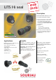

UTS Hi seal
3
Note : all dimensions are in mm
Connector family UTS
UTS
7
6
-
JC
8
8
E
E
2
2
P
S
-
-
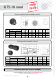
Body variation
6 Cable plug + backshell
7 Jam nut receptacle
0
Square flange receptacle
Backshell : JC = Backshell (only for plug) / No digit = No backsell (only for receptacle)
Shell size :
8, 10, 12, 14, 18
Contact type
E = Handsolder contacts / R = Crimp contacts* / D = PC tail contacts*
Insert arrangement - see previous page
Contact gender : P = Pin contacts / S = Socket contacts
Insert rotation : No digit = Normal / W, X, Y, Z = Different orientations - see below
Ordering information
* Please consult factory
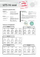
Insert orientation - Insert rotated in body (viewed from front face of male insert)
Normal
W
X
Y Z
* 8-98 layout, W and X non standard ortientations / 10-7 & 12-14 layouts, X non standard orientation
Shell size 8 10 12 14 18
Layouts 2 3 3A(98)* 4 33 6 7* 98 3 8 10 2 14* 5 12 15 18 19 11 32 30
Angle in
degrees
W 58 60 60 45 90 90 90 90 - 90 60 - 45 40 43 17 15 30 62 5 180
X 122 210 210 - - - - 180 - 112 155 - 92 90 110 90 165 119 138 193
Y - - - - - - - 240 180 203 270 - 184 - 155 180 315 241 222 285
Z - - - - - - - 270 - 292 295 - 273 - 234 270 - 340 265 350
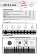
Range presentation
Square flange receptacle with handsolder contacts
Shell
size
Part numbers
A B
±0.15
C Ø D
±0.15
E
±0.25
F
±0.25
G
±0.1
Ø I
±0.10
Ø J
±0.10
Male contact Female contact
8 UTS08E - - P - UTS08E - - S - 21.5 2.3 11.7 12.0 15.1 21.0 3.2 15.5 12.5
10 UTS010E - - P - UTS010E - - S - 21.5 2.3 11.7 15.0 18.3 23.8 3.2 17.3 15.1
12 UTS012E - - P - UTS012E - - S - 21.5 2.3 11.7 19.0 20.6 26.2 3.2 21.8 18.2
14 UTS014E - - P - UTS014E - - S - 21.5 2.3 11.7 22.2 23.0 28.6 3.2 25.0 21.5
18 UTS018E - - P -* UTS018E - - S -* 21.5 2.5 11.7 28.5 27.0 33.3 3.2 31.8 27.8
ØD
±0.15
C max.
Shell
E
±0.25
E
±0.25
J
I
ØG
±0.1
B
A max.
F
±0.25
E
±0.25
E
±0.25
F
±0.25
4 holes ØG
±0.1
PANEL CUT OUT
Thread