
Infrared Broilers User Manual


INFRARED BROILER
OWNER’S MANUAL 1199790 REV 0 (6/14)
PAGE
14
OF 46
INSTALLATION
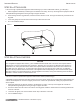
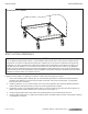
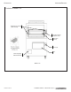
5. Bolt the frames of the sections together.
6. Connect the front manifolds using the pipe-union.
7. Attach the trim-strip between the section tops.
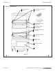
8. Install the continuous front-rail, if ordered.
9. Slide control knobs onto their shafts (to operate the sections during the installation procedure), but do not yet
reattach valve panels or front-panel trim pieces.
STEP 5: CONNECT ELECTRICITY (OVEN BASE)
A wiring diagram is located behind on the rear of the oven. Be sure that the input voltage and phase match the
requirements shown on the serial plate.
Oven-bases ordered with a 115V, 60Hz, single-phase electrical rating are factory-supplied with a three-wire cord with
a three-prong plug that ts any standard three-prong grounded receptacle. Each standard oven requires a 15 ampere
supply, while each convection oven requires a 20 ampere supply.
Oven-bases ordered with a 208/236V, 60Hz, single- or three-phase electrical rating are factory-equipped with a two-pole
terminal block located behind cover plate located on the rear of the unit. To connect the supply wires, remove the cover
plate. Route the supply wires and the grounding wire through the strain relief tting to the terminal block. Insert the supply
wires, one each, into the two poles of the terminal block and tighten the screws. Insert the ground wire into the grounding
lug and tighten the screw. Re-attach the cover plate.
Three phase units are wired as above, using only two supply wires. The third wire is not used and must be properly
terminated.
All units are shipped wired as specied by factory order. Conversion between single-phase and three-phase can be
accomplished by referring to phase loading and line amperes chart on the wiring diagram for wire size and ampere
requirements.
STEP 6: CONNECT ELECTRICITY (BROILER)
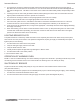
Wiring diagram location will vary depending on the model:
- For broilers with an oven base the wiring diagram is located on the rear of the oven base.
- For free standing broilers the wiring diagram is located behind the lter (See Figure 1)
Be sure that the input voltage and phase match the requirements shown on the serial plate.
Broilers ordered with a 115V, 60Hz, single-phase electrical rating are factory-supplied with a three-wire cord with a three-
prong plug that ts any standard three-prong grounded receptacle. Each standard oven requires a 15 ampere supply.
Broilers ordered with a 208/240V, 60Hz, single phase electircal rating are factory supplied with a three wire cord. A plug,
(not provided) must be installed.
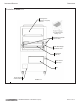
An optional electic element rated at 3000 watts, 208/240V, is available in the wiring oven. ** This is indicated on the serial
plate by the prex EW. A seperate electric supply, 208/240V, single phase, 20 AMP must be connected to the leads in a
terminal box at the rear, near the top of the broiler. This installation must conrm with local codes, or in their absence, with
the NATIONAL ELECTRICAL CODE ANSI/NFPA 70-Latest Edition. Canadian installation must comply with CSA C22.1
Canadian Electrical Code Parts I and II.
STEP 7: CONNECT GAS SUPPLY
If the Southbend equipment is being installed at over 2,000 feet altitude and that information was not specied when
ordered, contact the appropriate authorized Southbend Service Representative or the Southbend Service Department.
Failure to install with proper orice sizing will result in poor performance and may void the warranty.
Southbend equipment is design-certied for operation on natural or propane gases. The units are shipped congured and
adjusted for the type of gas specied by the purchaser, which is indicated on the serial plate (see Figure 1). Connect the
equipment ONLY to the type of gas for which it is congured and adjusted.