8" & 60" EVS TOOLROOM LATHES MODEL SB1016 - 220V Three Phase MODEL SB1036 - 440V Three Phase OWNER'S MANUAL Hundreds of Thousands of Lathes Sold With a Tradition of Q uality Since 1906! © August, 2010 by South Bend Lathe Co. For Machines Mfg.
Scope of Manual This manual helps the reader understand the machine, how to prepare it for operation, how to control it during operation, and how to keep it in good working condition. We assume the reader has a basic understanding of how to operate this type of machine, but that the reader is not familiar with the controls and adjustments of this specific model. As with all machinery of this nature, learning the nuances of operation is a process that happens through training and experience.
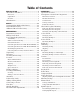
Table of Contents INTRODUCTION ....................................................3 About These Machines......................................... 3 Foreword ............................................................. 3 Capabilities ......................................................... 3 Features .............................................................. 3 Identification ........................................................ 4 SAFETY................................................................
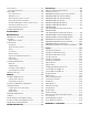
Power Feed ......................................................... 54 Power Feed Controls .......................................... 54 Threading ........................................................... 56 Power Feed Lever .............................................. 56 Half Nut Lever .................................................. 56 Thread Dial & Chart Overview .......................... 56 Using Thread Dial and Chart ............................. 57 Understanding Thread & Feed Rate Chart ......
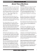
For Machines Mfg. Since 7/09 INTRODUCTION INTRODUCTION Model SB1016/SB1036 About These Machines Foreword Features "The screw cutting engine lathe is the oldest and most important of machine tools and from it all other machine tools have been developed. It was the lathe that made possible the building of the steamboat, the locomotive, the electric motor, the automobile and all kinds of machinery used in industry.
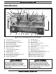
INTRODUCTION Model SB1016/SB1036 For Machines Mfg. Since 7/09 Identification D A B G E C AD L H F J K I AC AB AA M Z N Y W X V U T S R Q P O Figure 1. The 18" x 60" Variable Speed Toolroom Lathe (EVS). A. B. C. D. E. F. G. H. I. J. K. L. M. N. O.
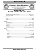
For Machines Mfg. Since 7/09 INTRODUCTION Model SB1016/SB1036 0RGHO 6% 6RXWK %HQG [ /DWKH 9 2TQFWEV &KOGPUKQPU 9GKIJV NDU 9KFVJ UKFG VQ UKFG Z &GRVJ HTQPV VQ DCEM Z *GKIJV Z Z KP (QQVRTKPV .
Model SB1016/SB1036 INTRODUCTION For Machines Mfg. Since 7/09 .
For Machines Mfg. Since 7/09 INTRODUCTION Model SB1016/SB1036 6JTGCFKPI +PHQ 0WODGT QH .QPIKVWFKPCN (GGFU 4CPIG QH .
Model SB1016/SB1036 INTRODUCTION For Machines Mfg. Since 7/09 0RGHO 6% 6RXWK %HQG [ /DWKH 9 2TQFWEV &KOGPUKQPU 9GKIJV NDU 9KFVJ UKFG VQ UKFG Z &GRVJ HTQPV VQ DCEM Z *GKIJV Z Z KP (QQVRTKPV .
For Machines Mfg. Since 7/09 INTRODUCTION Model SB1016/SB1036 .
Model SB1016/SB1036 INTRODUCTION For Machines Mfg. Since 7/09 6JTGCFKPI +PHQ 0WODGT QH .QPIKVWFKPCN (GGFU 4CPIG QH .
For Machines Mfg. Since 7/09 SAFETY Model SB1016/SB1036 SAFETY Understanding Risks of Machinery Operating all machinery and machining equipment can be dangerous or relatively safe depending on how it is installed and maintained, and the operator's experience, common sense, risk awareness, working conditions, and use of personal protective equipment (safety glasses, respirators, etc.). The owner of this machinery or equipment is ultimately responsible for its safe use.
Model SB1016/SB1036 SAFETY For Machines Mfg. Since 7/09 5. Entanglement: Loose clothing, gloves, neckties, jewelry or long hair may get caught in moving parts, causing entanglement, amputation, crushing, or strangulation. Reduce this risk by removing/securing these items so they cannot contact moving parts. 11. Chuck Keys or Adjusting Tools: Tools used to adjust spindles, chucks, or any moving/ rotating parts will become dangerous projectiles if left in place when the machine is started.
For Machines Mfg. Since 7/09 SAFETY Model SB1016/SB1036 Additional Metal Lathe Safety 1. Clearing Chips: Metal chips can easily cut bare skin—even through a piece of cloth. Avoid clearing chips by hand or with a rag. Use a brush or vacuum to clear metal chips. 2. Chuck Key Safety: A chuck key left in the chuck can become a deadly projectile when the spindle is started. Always remove the chuck key after using it.
Model SB1016/SB1036 P R E PA R AT I O N For Machines Mfg. Since 7/09 PREPARATION Preparation Overview Things You'll Need The purpose of the preparation section is to help you prepare your machine for operation. The list below outlines the basic process. Specific steps for each of these points will be covered in detail later in this section. The typical preparation process is as follows: 1. Unpack the lathe and inventory the contents of the box/crate. 2. Clean the lathe and its components. 3.
For Machines Mfg. Since 7/09 P R E PA R AT I O N Power Supply Requirements Availability Before installing the machine, consider the availability and proximity of the required power supply circuit. If an existing circuit does not meet the requirements for this machine, a new circuit must be installed. To minimize the risk of electrocution, fire, or equipment damage, installation work and electrical wiring must be done by a qualified electrician in accordance with all applicable codes and standards.
P R E PA R AT I O N Model SB1016/SB1036 For Machines Mfg. Since 7/09 Circuit Requirements for 220V (Model SB1016) Correcting Phase Polarity (Yaskawa Drive) This machine is prewired to operate on a 220V power supply circuit that has a verified ground and meets the following requirements: This sub-section is only provided for troubleshooting by a qualified electrician.
For Machines Mfg. Since 7/09 P R E PA R AT I O N — If one or more pump motors do not pump or rotate in the incorrect direction, locate the master power switch on the lathe, and swap any two of the L1, L2, or L3 incoming power leads shown in Figure 4. Hot L1 L2 Hot L3 Hot Ground Swap any Two of These Wires DISCONNECT SWITCH (as recommended) L1 L2 1 3 Variable Frequency Drive (Figure 3) Model SB1016/SB1036 Master Power Switch (Figure 4) L3 5 MASTER POWER SWITCH 2 L1 4 L2 6 L3 Figure 4.
Model SB1016/SB1036 P R E PA R AT I O N For Machines Mfg. Since 7/09 Unpacking C A This item was carefully packaged to prevent damage during transport. If you discover any damage, please immediately call Customer Service at (360) 734-1540 for advice. You may need to file a freight claim, so save the containers and all packing materials for possible inspection by the carrier or its agent. B F E G Inventory Main Inventory 1: (Figure 6) Qty A. Steady Rest Assembly....................................
For Machines Mfg. Since 7/09 P R E PA R AT I O N Model SB1016/SB1036 Cleaning & Protecting The unpainted surfaces are coated at the factory with a heavy-duty rust preventative that prevents corrosion during shipment and storage. The benefit of this rust preventative is that it works very well. The downside is that it can be time-consuming to thoroughly remove. Be patient and do a careful job when cleaning and removing the rust preventative.
P R E PA R AT I O N Model SB1016/SB1036 For Machines Mfg. Since 7/09 Weight Load Location Physical Environment The physical environment where your machine Physical Environment is operated is important for safe operation and Electrical Installation longevity of parts. For best results, operate this machine in a dry environment that is free from Lighting excessive moisture, hazardous or flammable Weight chemicals, Load airborne abrasives, or extreme Space Allocation conditions.
For Machines Mfg. Since 7/09 P R E PA R AT I O N Lifting & Moving Model SB1016/SB1036 (Loooking at Lifting Setup from Tailstock End) To Forklift or Lifting Hook This machine and its parts are heavy! Serious personal injury may occur if safe moving methods are not used. To reduce the risk of a lifting or dropping injury, ask others for help, and use power equipment and guide rods.
Model SB1016/SB1036 P R E PA R AT I O N Leveling & Mounting You must level your machine and either use the included foot pads and leveling hardware or bolt your lathe to the floor. Because mounting your lathe to the floor with permanent hardware is an optional step and floor materials may vary, floor mounting hardware is not included. To level the machine, use a precision level to make sure the bedways are level from side-toside and from front-to-back.
For Machines Mfg. Since 7/09 P R E PA R AT I O N Assembly With the exception of the handwheel handles, the lathe is shipped fully assembled. To install the handwheel handles, thread the large handle into the carriage handwheel and the small handle into the cross slide handwheel, as shown in Figure 14. Model SB1016/SB1036 In addition to the gearboxes, we also recommend that you lubricate all other points on the machine at this time.
P R E PA R AT I O N Model SB1016/SB1036 For Machines Mfg. Since 7/09 Connecting to Power Due to the complexity required for planning, bending, and installing the conduit necessary for a code-compliant hardwire setup, an electrician or other qualified person MUST perform this type of installation. Hardwire setups typically require power supply wires to be enclosed inside of a solid or flexible conduit, which is securely mounted at both ends with the appropriate conduit fittings.
For Machines Mfg. Since 7/09 P R E PA R AT I O N Test Run After all preparation steps have been completed, the machine and its safety features must be tested to ensure correct operation. If you discover a problem with the operation of the machine or its safety components, shut the machine down, disconnect it from power, and do not operate it again until you have resolved the problem. Note: The variable speed on this machine is controlled by a frequency drive unit with sensitive electronics.
P R E PA R AT I O N Model SB1016/SB1036 8. Move the headstock feed direction lever to the (neutral) position (see Figure 20). FORWARD For Machines Mfg. Since 7/09 11. Make sure that the master power switch is OFF, shown in Figure 23. Next, connect the lathe to the power source, and turn the master power switch ON. NEUTRAL REVERSE Master Power Switch Figure 20. Feed direction lever in neutral. 9.
For Machines Mfg. Since 7/09 P R E PA R AT I O N Model SB1016/SB1036 19. Push the foot brake. The lathe should come to a quick stop. — If the foot brake has no effect on the lathe, push the stop button, and refer to V-Belts and Brake & Switch on Page 81 to make any required adjustments. Oil Pump Sight Glass 20. Remove the lathe headstock side cover. The kill switch shown in Figure 27 should prevent the lathe from starting while this cover is removed. Figure 25. Oil pump sight glass. 14.
Model SB1016/SB1036 P R E PA R AT I O N 23. Lift the chuck guard shown in Figure 28, and try to start the lathe again. The cover kill switch should prevent the lathe from starting while the guard is open. Chuck Guard Cutting Fluid Pump Switch For Machines Mfg. Since 7/09 Spindle Break-In It is essential to closely follow the proper break-in procedures to ensure trouble-free performance.
P R E PA R AT I O N For Machines Mfg. Since 7/09 4. Move the quick change range lever to the middle (neutral) position, as shown in Figure 31. Model SB1016/SB1036 Carriage Lock Disengaged LOW Engaged Neutral Disengaged HIGH Half Nut Lever Engaged Feed ON/OFF Lever Figure 33. Halfnut and carriage feed levers shown in the disengaged positions. Move the spindle ON/OFF lever to the OFF (center) position, as shown in Figure 34. 7. Figure 31. Quick change gearbox in neutral position. 5.
Model SB1016/SB1036 P R E PA R AT I O N For Machines Mfg. Since 7/09 LOW Neutral NEVER attempt to shift the headstock or quick change gearbox when the lathe is in operation. Gear clash causing tooth damage will result. Only use the gear shifting levers when the spindle id stopped. 8. Turn the lathe ON. 9.
For Machines Mfg. Since 7/09 O P E R AT I O N Model SB1016/SB1036 OPERATION Operation Overview To complete a typical operation, the operator does the following: The purpose of this overview is to provide the novice machine operator with a basic understanding of how the machine is used during operation, so they can more easily understand the controls discussed later in this manual. 1.
O P E R AT I O N Model SB1016/SB1036 Description of Controls & Components Refer to the following figures and descriptions to learn about the basic controls of this machine. Main Power Control Master Power Switch: The rotary switch shown in Figure 37 toggles incoming power ON/OFF to the lathe. It also prevents the electrical box door from being opened when the switch is ON.
O P E R AT I O N For Machines Mfg. Since 7/09 K. Cutting Fluid Pump Switch: Start/stops the cutting fluid pump motor. L. Jog Button: Turns the spindle motor ON while being pressed and held. S. Way Oil Oil Pump: Draws oil from the apron case and lubricates the carriage and ways through various oil ports. T. Carriage Lock: Secures the carriage in place for greater rigidity and accuracy when using the cross or compound slide for the machining operation. U.
O P E R AT I O N Model SB1016/SB1036 Tailstock Controls AB. Quill: The quill has an MT#5 bore, metric and inch scale, and drift slot to remove tightfitting tooling. For Machines Mfg. Since 7/09 AH. Tailstock Lock Bolt: Tightens a secondary tailstock clamp to assist the primary tailstock lock lever and clamp. AC. Quill Lock Lever: Locks the quill in position. AI. Offset Scale: Indicates the distance of tailstock offset from the spindle centerline with arbitrary marks. AD.
For Machines Mfg. Since 7/09 O P E R AT I O N Foot Brake This lathe is equipped with a foot brake (Figure 45) to quickly stop the spindle. Pushing the foot brake while the spindle is ON cuts power to the motor and stops the spindle. Once stopped, the spindle lever MUST be returned to the neutral position before the spindle can be restarted. Spindle ON/OFF Lever Model SB1016/SB1036 Chuck & Faceplate Mounting This lathe is shipped with the 3-jaw chuck installed.
Model SB1016/SB1036 O P E R AT I O N One at a time, use the chuck key to turn each of the camlocks counterclockwise until the cam line aligns with the cam release datum line, as shown in Figure 47. As you turn the camlocks, they will rise up slightly from the spindle body. 3. Cam Release Datum Line and Cam Line Mounting Chuck or Faceplate The 4-jaw chuck is shipped with six camlock studs that may have to be installed before chuck mounting.
For Machines Mfg. Since 7/09 6. O P E R AT I O N Tighten camlocks in a star pattern to draw the chuck up evenly on all sides while reducing chance of misalignment, and make sure to tighten camlocks in an incremental manner to ensure that no camlock gets fully tightened all at once (i.e., snug the camlocks on the first pass, then moderately tighten on the next pass, then fully tighten on the third pass). As you tighten the camlocks, the chuck or faceplate will snug up onto the spindle nose.
Model SB1016/SB1036 O P E R AT I O N For Machines Mfg. Since 7/09 Make sure that the cam-lock studs can rotate back and forth against the head of the locking cap screw (see Figure 54). 5. Depth Mark Chuck Surface Camlock Stud Can Rotate Back/Forth Slightly Chuck/Faceplate Cap Screw Installed & Tight Figure 52. Example of camlock stud depth mark. Figure 54. Camlock stud and cap screw correctly installed. Camlock Stud Depth Mark is Even with Chuck or Faceplate Surface Chuck/Faceplate 6.
For Machines Mfg. Since 7/09 O P E R AT I O N Model SB1016/SB1036 Changing Jaws 3-Jaw Chuck Refer to Chuck & Faceplate Mounting instructions on Page 35 to mount the 3-jaw chuck to the spindle. The 3-jaw scroll-type chuck included with this lathe features hardened steel jaws that center the workpiece. When the operator opens or closes the jaws with the chuck key, the jaws move in unison. There are two sets of removable hardened steel jaws included with the 3-jaw chuck—inside and outside jaws.
Model SB1016/SB1036 O P E R AT I O N — If installed correctly, the jaws converge together at the center of the chuck. — If the jaws do not come together, the initial thread was missed on one of the jaws. Remove all the jaws and start again. Mounting Workpiece Items Needed.....................................................Qty Chuck Key ............................................................. 1 Chuck Cradle or Plywood 3⁄4" (to protect bed) .... 1 To mount a workpiece in the 3-jaw chuck: 1.
For Machines Mfg. Since 7/09 6. O P E R AT I O N After the workpiece is held in place by the jaws, turn the chuck by hand and pay attention to the workpiece alignment. — If the workpiece is not correctly aligned for your operation, turn the chuck and make fine adjustments by slightly loosening one jaw and tightening the opposing jaw until the workpiece is correctly aligned (see Figure 61 for an example).
O P E R AT I O N Model SB1016/SB1036 Offsetting The tailstock can be offset from the spindle centerline for turning tapers. The offset movement is controlled by two opposing cap screws on the front and back sides of the tailstock (see Figure 63). For Machines Mfg. Since 7/09 Tool Needed Qty Hex Wrench 6mm ................................................. 1 Wrench 28mm .......................................................
For Machines Mfg. Since 7/09 O P E R AT I O N However, other tooling without lock tangs, such as the remaining four shown in Figure 66, can still be used if the following two conditions exist: 1. 2. If the potential torque load from smaller drill chucks, drill bits, and centers will not override the strength of the MT#5 tapered fit, the tool can be used. Usually the end of the arbor or tool that fits into the quill must be solid and a standard length.
Model SB1016/SB1036 O P E R AT I O N Aligning The offset of your lathe was aligned with the spindle centerline at the factory. We recommend that you take the time to ensure that the tailstock is aligned to your own desired tolerances, especially if you have changed the offset to cut shallow tapers. For Machines Mfg. Since 7/09 5. Install a center in the tailstock. 6. Attach a lathe dog to the piece of stock from Step 3, then mount it between the centers, as shown in Figure 69.
For Machines Mfg. Since 7/09 9. O P E R AT I O N Use calipers to measure both ends of the workpiece. — If the machined workpiece is thicker at the tailstock end, move the tailstock toward the operator 1⁄2 the distance of the amount of taper (see Figure 70). Model SB1016/SB1036 — If the machined workpiece is thinner at the tailstock end, move the tailstock away from the operator 1⁄2 the distance of the amount of taper (see Figure 71). Looking down from above.
Model SB1016/SB1036 O P E R AT I O N Faceplate For Machines Mfg. Since 7/09 Non-Cylindrical Workpiece Refer to Chuck & Faceplate Mounting instructions on Page 35 to mount the faceplate to the spindle. The 15" faceplate included with your lathe offers a wide range of uses, including machining nonconcentric workpieces, straight turning between centers, off-center turning, and boring. Clamp The tools needed for mounting a workpiece will vary depending on the type of setup you have. Faceplate Figure 72.
For Machines Mfg. Since 7/09 O P E R AT I O N Model SB1016/SB1036 Centers Mounting Center in Spindle Figure 74 shows the dead centers included with the lathe. In addition, an MT#7–MT#5 tapered spindle sleeve is included for mounting centers in the spindle. 1. DISCONNECT LATHE FROM POWER! 2. Thoroughly clean and dry the tapered mating surfaces of the spindle bore, tapered sleeve, and the center, making sure that no lint or oil remains on the tapers. 3.
Model SB1016/SB1036 O P E R AT I O N Mounting Center in Tailstock Either the carbide-tipped dead center or a live center can be mounted in the tailstock. Mounting instructions are the same for both. To mount a center in the tailstock: 1. DISCONNECT LATHE FROM POWER! 2. Thoroughly clean and dry the tapered mating surfaces of the tailstock quill bore and the carbide-tipped dead center, making sure that no lint or oil remains on the tapers. 3.
For Machines Mfg. Since 7/09 O P E R AT I O N 5. Close the steady rest and tighten the lock knob. 6. Loosen the three leaf screws. Without causing any deflection in the workpiece, use the finger adjustment knobs to position the finger rollers against the workpiece. 7. Tighten the leaf screws. Note: The finger rollers should properly support the workpiece but allow it to freely rotate. Compound Slide The compound slide handwheel has an indirectread graduated collar.
O P E R AT I O N Model SB1016/SB1036 4-Way Tool Post The 4-way tool post is mounted on top of the compound slide, and allows a maximum of four tools to be loaded simultaneously. Quick indexing to different tools is accomplished by loosening the top handle, rotating the tool post to the desired position, then re-tightening the handle to lock the tool into position. For Machines Mfg.
O P E R AT I O N For Machines Mfg. Since 7/09 Tools Needed Qty Tool Post T-Wrench............................................... 1 Steel Shim ............................................. As Needed Cutting Tool........................................................... 1 Fine Ruler .............................................................. 1 Tailstock Center .................................................... 1 To align the cutting tool with the tailstock center: 1. 2.
O P E R AT I O N Model SB1016/SB1036 For Machines Mfg. Since 7/09 Manual Feed Spindle Speed These three handwheels (see Figure 83) manually position and control the cutting tool for lathe operations. Using the correct spindle speed is important for safe and satisfactory results, as well as maximizing tool life. Cross Slide Handwheel Compound Slide Handwheel Carriage Handwheel Figure 83. Carriage handwheels.
For Machines Mfg. Since 7/09 O P E R AT I O N Model SB1016/SB1036 Setting Spindle Speed Make sure the variable speed dial is turned all the way to the left (counterclockwise) before turning the lathe ON, or the spindle may start up at a dangerously high rate of speed. 1. Make sure the spindle is turned OFF and it has come to a complete stop. 2. Use the chart in Figure 85 to determine the available spindle speed range closest to your calculated spindle speed.
Model SB1016/SB1036 O P E R AT I O N For Machines Mfg. Since 7/09 Power Feed FORWARD On this lathe, both the carriage and cross slide have power feed capability. The power feed system is protected by an adjustable feed rod clutch located on the input side of the apron. The rate that these components move (feed rate) is controlled by how the quick change gearbox levers are configured. Feed rate and spindle speed must be considered together.
O P E R AT I O N For Machines Mfg. Since 7/09 3. Push down on the feed ON/OFF lever (see Figure 91) on the front of the apron to engage power feed for either the carriage or the cross slide. 4. Push the feed selection knob in to select carriage feed, or pull the feed selection knob out to select cross feed. 5. Adjust the feed clutch knob, shown in Figure 92, to set at which point the feed clutch will slip to avoid feed system overload.
O P E R AT I O N Model SB1016/SB1036 For Machines Mfg. Since 7/09 Half Nut Lever Threading If you are unfamiliar with how to cut threads on a lathe, we strongly recommend that you read books, review industry trade magazines, or get formal training before beginning any attempting any threading projects. Power Feed Lever The feed ON/OFF lever must be in the fully up disengaged position or the internal lockout will prevent the half nut lever from applying the half nut.
O P E R AT I O N For Machines Mfg. Since 7/09 Model SB1016/SB1036 Using Thread Dial and Chart TPI 2-54 Not Divisible By 4 Find the TPI (threads per inch) that you want to cut in the left column (see Figure 96), then reference the dial number to the right of it. The dial numbers indicate when to engage the half nut for a specific thread pitch. The thread dial chart can also be found on the front of the thread dial housing.
Model SB1016/SB1036 O P E R AT I O N For Machines Mfg. Since 7/09 Other Fractional TPI 27⁄8 TPI Select one position and always return to that single position on the thread dial for cutting the TPI shown in Figure 101. Typically 1 on the thread dial is selected for ease of memory. You cannot use the thread dial when cutting this thread.
For Machines Mfg. Since 7/09 O P E R AT I O N Model SB1016/SB1036 Understanding Thread & Feed Rate Chart A complete threading and feed rate chart is located on the face of the headstock that shows all available threading and feed configurations for your lathe. Chart use is described below. Positioning Gearbox Levers To cut a thread or establish a particular feed rate, you may need to first reposition the transposing gears located behind the end gear cover.
O P E R AT I O N Model SB1016/SB1036 Repositioning Change Gears For Machines Mfg. Since 7/09 24T + 56T Modular and Diametral Threading Symbol The factory has arranged the change gears in the "normal position" so all inch and metric threading and feed selections are available by shifting levers. However, if modular or diametral pitch threading is required, the "alternate position" must be used.
O P E R AT I O N For Machines Mfg. Since 7/09 Model SB1016/SB1036 Cutting Fluid System A pump delivers cutting fluid through a flex tube and nozzle. The pump is turned ON/OFF by the cutting fluid pump switch on the control panel. Flow is controlled by the valve lever on the flex tube (see Figure 107). BIOLOGICAL & POISON HAZARD! Use the correct personal protection equipment when handling cutting fluid. Follow federal, state, and fluid manufacturer requirements for proper disposal.
Model SB1016/SB1036 ACC ESSOR I ES For Machines Mfg. Since 7/09 ACCESSORIES Accessories This section includes the most common accessories available for your lathe, which may be available through your local South Bend Lathe Co. dealer. If you do not have a dealer in your area, please call us at (360) 734-1540 or email us at cs@southbendlathe.com.
For Machines Mfg. Since 7/09 ACC ESSOR I ES SB1279—10 Pc. Precision 5–C Collet Set Set of 10 collets sized from 1⁄8" - 3⁄4". Same quality as the individual collets, only packaged in one convenient set. Model SB1016/SB1036 SBL Gearhead T-Shirt SBL One Good Turn T-Shirt 100% Cotton, preshrunk T-shirts, available in sizes S, M, L, XL, 2XL, 3XL. Figure 111. Model SB1279 10 Pc. 5-C Collet Set.
Model SB1016/SB1036 MAINTENANCE MAINTENANCE Maintenance Schedule ! Always disconnect power to the machine before performing maintenance. Failure to do this may result in electrocution or accidental startup injury. Typically, each operator is responsible for ensuring proper care of the equipment. We strongly recommend all operators make a habit of following the daily maintenance procedures. For optimum performance from this machine, this maintenance schedule must be strictly followed.
Day 1 2 3 4 5 6 7 8 9 10 11 12 13 14 15 16 17 18 19 20 21 22 23 24 25 26 27 28 29 30 31 Change Cutting Fluid Make copies of this page to use each month. Keep each chart as a maintenance record for your South Bend Lathe. Date of next annual service: Change Apron Oil Change Headstock Oil Change Gearbox Oil Service Item s &!8 www.southbendlathe.
MAINTENANCE Model SB1016/SB1036 For Machines Mfg. Since 7/09 Oil Pressure Safety Switch Lubrication Headstock The headstock has a pressurized lubrication system that consists of an oil pump, a low oil pressure kill switch, a supply tank, oil hoses, and a manifold with oil distribution lines.
For Machines Mfg. Since 7/09 MAINTENANCE Model SB1016/SB1036 Checking & Adding Oil Changing Headstock Oil Oil Type...Mobil DTE Light or ISO 32 Equivalent Oil Amount .............................................. 4 Gallons Check/Add Frequency .................................... Daily Change Frequency ...................................
Model SB1016/SB1036 MAINTENANCE 3. Remove the headstock oil supply line from the check valve, as shown in Figure 121. 4. Push the rubber drain hose onto the headstock oil supply line, as shown in Figure 119. Use a hose clamp if required to ensure a tight connection. 8. For Machines Mfg. Since 7/09 Place a series of rags under the tank access cover to catch the residual oil in the tank when the tank access cover shown in Figure 120 is removed.
For Machines Mfg. Since 7/09 MAINTENANCE Model SB1016/SB1036 Priming the Oil Pump Quick Change Gearbox The lubrication system is also equipped with a check valve that is shown in Figure 121. This valve allows oil to flow to the headstock during pump operation, but prevents the oil from draining back into the tank and the pump from losing its prime when not in operation.
MAINTENANCE Model SB1016/SB1036 For Machines Mfg. Since 7/09 Apron Lead Screw Oil Type ...... Mobil Vactra 2 or ISO 68 Equivalent Oil Amount ............................................ As Needed Check/Add Frequency .................................... Daily Change Frequency ...................................Annually Oil Type ...... Mobil Vactra 2 or ISO 68 Equivalent Oil Amount ............................................ As Needed Lubrication Frequency...................................
For Machines Mfg. Since 7/09 MAINTENANCE Unpainted & Machined Surfaces Besides the ways and leadscrew, all other unpainted and machined surfaces should be wiped down daily to keep them rust-free and in top condition. This includes the top of the saddle, the cross slide, compound slide, tool post, chuck, feedrod, and any other surface you can find that could be vulnerable to rust if left unprotected (this especially includes any parts that may be exposed to water soluble cutting fluids).
MAINTENANCE Model SB1016/SB1036 For Machines Mfg. Since 7/09 Change Gears Lubricating Grease Type ............................................... NLGI#2 Frequency ................ Annually or When Swapping 1. DISCONNECT LATHE FROM POWER! 2. Remove the end gear cover. 3. Clean the change gears thoroughly with mineral spirits to remove all the old grease. Use a small brush if necessary to clean between the teeth. 4.
MAINTENANCE For Machines Mfg. Since 7/09 Cutting Fluid System The cutting fluid system holds 6 1⁄2 gallons. A pump pulls fluid from the tank and sends it to the valve, which controls the flow of cutting fluid through a universal hose and nozzle. When the valve is opened or closed, the fluid flows from the nozzle and drains into the chip drawer and into a catch tray that directs it back into the tank. Figure 131 shows many of these components and their locations.
Model SB1016/SB1036 MAINTENANCE 3. Changing Cutting Fluid When you replace the old cutting fluid, take the time to thoroughly clean out the chip drawer, catch tray, and chip drawer. Make sure to dispose of all old fluid according to local regulations. Cutting fluid is considered hazardous waste by the EPA. Follow all disposal and storage guidelines when changing and disposing of cutting fluid. For Machines Mfg.
For Machines Mfg. Since 7/09 8. 9. MAINTENANCE Pour out the remaining cutting fluid from the tank into the 5-gallon bucket and seal the bucket with its lid. Lift and slide the tank out far enough for cleaning. 10. Using mineral spirits and rags, clean and dry the tank. If a water soluble cutting fluid was used, use soap and hot water instead of mineral spirits. Model SB1016/SB1036 Cleaning Electrical Box The electrical box has two cooling fans (Figure 134) for the electrical box.
Model SB1016/SB1036 MAINTENANCE For Machines Mfg. Since 7/09 Machine Storage To prepare your machine for long-term storage (a year or more): If the machine is not properly prepared for storage, it may develop rust or corrosion. If decommissioning this machine, use the steps in this section to ensure that it remains in good condition for later use. 1. Run the lathe and bring all gearboxes to operating temperature, then drain and refill the all gearboxes with fresh oil. 2.
For Machines Mfg. Since 7/09 SERVICE SERVICE Backlash Adjustment Backlash is the amount of free play felt while switching rotation directions with the handwheel. This can be adjusted on the compound and cross slide leadscrews. Before beginning any adjustment, make sure that all associated components have been cleaned and re-lubricated. Reducing backlash to less than 0.001" is impractical. Avoid the temptation to overtighten the backlash set screw while adjusting.
SERVICE Model SB1016/SB1036 Leadscrew End Play Adjustment After a long period of time, you may find that the leadscrew develops a small amount of end play. This lathe is designed so that leadscrew end play can be easily removed with adjustment. Tools Needed: Qty Open End Wrench 36mm or 1 7⁄16" ........................ 1 Hex Wrench 3mm ................................................. 1 To remove leadscrew end play: 1. DISCONNECT LATHE FROM POWER! 2. Remove the three cap screws and end cover. 3.
For Machines Mfg. Since 7/09 SERVICE 4. Saddle Gibs The saddle on this lathe is equipped with opposing gibs that lie parallel with one another on either side of the saddle. To tighten the saddle and remove play, the front gib must move toward the tailstock, and the rear gib must move toward the headstock. Tools Needed: Qty Hex Wrench 6mm ................................................. 1 Standard Screwdriver #3 ......................................
SERVICE Model SB1016/SB1036 Tailstock Gib When the tailstock is offset, it slides along a dovetailed way that has a gib installed between the upper and lower tailstock halves. To maintain alignment and prevent the upper portion of the tailstock from tilting off-center when the tailstock is clamped to the ways, the gib must be fairly snug. Tools Needed: Qty Standard Screwdriver #3 ...................................... 1 Wrench 28mm .......................................................
SERVICE For Machines Mfg. Since 7/09 3. V-Belts V-belts stretch and wear with use, so check them on a monthly basis to ensure optimal power transmission. Replace all of the V-belts if any of them show signs of glazing, fraying, or cracking. To adjust the V-belts: DISCONNECT LATHE FROM POWER! 2. Remove the cover shown in Figure 145. Turn the hex nuts on the motor mount bolts shown in Figure 146 to move the motor mount plate up or down and adjust the V-belt tension.
Model SB1016/SB1036 SERVICE For Machines Mfg. Since 7/09 Brake Inspection & Replacement The linkage geometry on this lathe is non adjustable. Before replacing the brake shoes, verify that all fasteners are tight, and all clevis pins and yokes have minimal wear. As pivot points wear, the increased slop in the linkage absorbs the usable stroke that is required for full brake application.
For Machines Mfg. Since 7/09 SERVICE 5. Place sheet of wood on the ways to protect them when the chuck is removed. 6. Using the appropriate lifting apparatus, remove the chuck as shown in Figure 148. Brake Linkage Cover Model SB1016/SB1036 Plunger and Cam Lobe Motor Kill Limit Switch Figure 149. Brake pedal motor kill switch. Figure 148. Removing the 3-jaw chuck from a spindle nose. 7. Remove the cap screws that fasten the brake linkage cover shown in Figure 149 to the headstock. 8.
Model SB1016/SB1036 SERVICE 11. Have your assistant press on the brake pedal a few times while you watch all of the brake linkage for any loose fasteners or worn pivot points and pins. Tighten or replace parts as required. 12. Have your assistant step on and hold the brake pedal to lock the drum in place. 13. Remove the drum retaining cap screw shown in Figure 151. 14. Remove the brake drum, E-Clip, and shoes shown in Figure 151, and the brake shoes. 15. Use mineral spirits to clean the drum.
SERVICE For Machines Mfg. Since 7/09 Leadscrew Shear Pin Replacement 3. Model SB1016/SB1036 Rotate the shroud washer so the cutout in the washer aligns with the shear pin head, as shown in Figure 154. Shroud Washer If the shear pin has broken, do not improvise by inserting a roll pin, cotter pin, steel dowel, or nail. Should the pin need to shear again, catastrophic gearbox damage may result. Order extras or make your own set of shear pins using the specifications shown in Figure 152.
Model SB1016/SB1036 SERVICE Use the magnet to remove the shear pin head, then rotate the lathe spindle by hand to line up the inner and outer bores, as shown in Figure 156. Next, use the magnet to remove the other half of the broken shear pin when it becomes visible. 7. Inner Bore For Machines Mfg. Since 7/09 10.
For Machines Mfg. Since 7/09 SERVICE Gap Removal & Installation The gap insert (Figure 160), is a portion of the lathe bed directly under the spindle that can be removed to create additional space for turning large diameter parts. Model SB1016/SB1036 2. Remove the two way-end cap screws, and way set screws shown in Figure 161. 3. Tighten the two dowel pin jack nuts (Figure 161) until the pins are pulled free from the gap insert. 4.
WAR R ANT Y Model SB1016/SB1036 For Machines Mfg. Since 7/09 TROUBLESHOOTING If you need replacement parts, or if you are unsure how to do any of the solutions given here, feel free to call us at (360) 734-1540. Symptom Machine does not start or a circuit breaker trips. Possible Cause Possible Solution 1. (First time operation only) Lathe may be wired with the incorrect phase polarity. 1. Correct phase polarity (refer to Page 16 for details). 2. Emergency stop push-button is engaged or at fault.
For Machines Mfg. Since 7/09 Symptom WAR R ANT Y Possible Cause Model SB1016/SB1036 Possible Solution 1. Workpiece is unbalanced. 1. Re-install workpiece as centered with the spindle bore as possible. 2. Loose or damaged belt(s). 2. Tighten/replace the belt as necessary (Page 81). 3. V-belt pulleys are not properly aligned. 3. Align the V-belt pulleys. 4. Worn or broken gear present. 4. Inspect gears and replace if necessary. 5. Chuck or faceplate has become unbalanced. 5.
WAR R ANT Y Model SB1016/SB1036 Symptom Possible Cause For Machines Mfg. Since 7/09 Possible Solution Workpiece is tapered. 1. Headstock and tailstock are not properly aligned with each other. 1. Realign the tailstock to the headstock spindle bore centerline (Page 44). Chuck jaws will not move or do not move easily. 1. Chips lodged in the jaws or scroll plate. 1. Remove jaws, clean and lubricate scroll plate, then replace jaws. Carriage will not feed, or is hard to move. 1.
For Machines Mfg. Since 7/09 ELECTRICAL Model SB1016/SB1036 ELECTRICAL Electrical Safety Instructions These pages are accurate at the time of printing. In the constant effort to improve, however, we may make changes to the electrical systems of future machines. Study this section carefully. If you see differences between your machine and what is shown in this section, call Technical Support at (360) 734-1540 for assistance BEFORE making any changes to the wiring on your machine. 1.
ELECTRICAL Model SB1016/SB1036 For Machines Mfg. Since 7/09 wiring overview Wiring Overview Power Supply Connection Page 101. Electrical Box, Pages 94–95. Spindle RPM Sensor, Page 102. Work Lamp, Page 102. Chuck Guard Safety Switch, Page 102. Brake Limit Safety Switch, Page 102. End Gear Cover Safety Switch, Page 102. Spindle ON/OFF Switch, Page 101. Oil Pressure Switch, Page 98. Cutting Fluid Pump Motor, Page 99. Oil Pump Motor, Page 98. Control Panel, Page 100. Spindle Motor, Page 97.
For Machines Mfg. Since 7/09 ELECTRICAL Model SB1016/SB1036 SB1016/36 Component Location Index Work Lamp, Page 102. visual index Cooling Fan, Page 94. Electrical Box, Pages 94–95. Master Power Switch, Page 94. Cutting Fluid Pump Motor, Page 99. Brake Pedal Safety Switch, Page 102. Control Panel, Page 100. Spindle Switch (Behind Splash Guard), Page 101. Spindle Motor, Page 97. End Gear Cover Safety Switch, Page 102. Chuck Guard Limit Switch, Page 102. Spindle RPM Sensor, Page 102.
L3 6 5 L1 2 1 3 1 L1 4 L2 6 2 L3 MASTER POWER SWITCH 5 3 11 L1 0 2 KR1 To Page 95. 9 220 8 COM L4 19 20 12 13 14 63 64 L1 L2 L3 L1 To Varispeed Unit, Page 95. 6 7 L3 COOLING FAN L3 L11 A E To Page 95. C D SB1016/36 Electrical Box Wiring 3 A1 7 9 5 6 8 11 5 A1 0 0 L13 L11 24 TRANSFORMER CIRCUIT BOARD KR4 L2 L1 0 220 380 400 415 440 L3 B ELECTRICAL To Page 95.
U U/T1 V V/T2 W W/T3 U W W B1 L11 B1 V1 U1 0 1 2 1600W/35 3 4 5 A1 THERMAL RESISTOR 2 NC L3 8 9 B2 2 L3 L2 5 4 L3 97 98 L11 To Page 94. To Chuck Guard Safety Switch, Page 102. To Work Lamp, Page 102. COOLING FAN W2 6 T3 NO L4 L11 8 T4 7 To Spindle RPM Sensor, Page 102. 2 V2 T2 U2 96 6 T3 L11 3 THERMAL RELAY 4 NC T2 2 T1 95 3 L2 L3 CONTACTOR Allen Bradley C09400 AMP L1 2 2 T1 1 L11 L13 To Spindle Switch, Page 101.
Model SB1016/SB1036 ELECTRICAL For Machines Mfg. Since 7/09 box photo SB1016/36 Electrical Box Fig. 163. Electrical box.
WAR R ANT Y For Machines Mfg. Since 7/09 SB1016 220V Spindle Motor Model SB1016/SB1036 spindle and pump motor W6 W2 U5 U1 U6 V1 Yl V5 L13 U2 W1 W5 L11 V2 V6 W V Junction Box U Ground SPINDLE MOTOR (220V) Figure 164. SB1016 Spindle motor location. To Electrical Box, Page 95. SB1036 440V Spindle Motor W5 W2 W6 U1 U5 V1 Yl U6 U2 W1 V6 L13 L11 V2 V5 W V U Junction Box Ground SPINDLE MOTOR (440V) Figure 165. SB1036 Spindle motor location. To Electrical Box, Page 95.
ELECTRICAL Model SB1016/SB1036 For Machines Mfg. Since 7/09 SB1016 220V Oil Pump Motor & Pressure Sensor To Electrical Box, Page 95. OIL PRESSURE SENSOR 2 11 X Oil Pressure Sensor U2 U5 U2 U1 V1 V2 V5 W1 W2 W5 Oil Pump Motor U2 V2 W2 Ground OIL PUMP MOTOR (220V) Figure 166. SB1016 Oil pump motor & pressure sensor location. To Electrical Box, Page 95. SB1036 440V Oil Pump Motor & Pressure Sensor To Electrical Box, Page 95.
ELECTRICAL For Machines Mfg. Since 7/09 Model SB1016/SB1036 SB1016 220V Cutting Fluid Pump Wiring To Electrical Box, Page 95. Cutting Fluid Pump 2 3 1 U1 V1 W1 5 W1 6 4 V1 Figure 168. SB1016 Cutting fluid pump location. Ground Ground CUTTING FLUID PUMP MOTOR (220V) SB1036 440V Cutting Fluid Pump Wiring To Electrical Box, Page 95. Cutting Fluid Pump 2 3 1 U1 V1 W1 5 W1 6 4 V1 Figure 169. SB1036 Cutting fluid pump location.
ELECTRICAL Model SB1016/SB1036 For Machines Mfg. Since 7/09 SB1016/36 Control Panel Wiring control panel and Control Panel Figure 170. Control panel location. To Electrical Box, Page 94. To Circuit Board, Page 94. To Main Junction Block, Page 94. C D L L11 3 14 X B 4 2 X 12 To Circuit Board, Page 94. E A COM K L13 To Main Junction Block, Page 94.
For Machines Mfg. Since 7/09 ELECTRICAL Model SB1016/SB1036 spindle rotation and power conntection SB1016/36 Spindle ON/OFF Switch Spindle Rotation Switches To Main Junction Block, Page 95. COMMON 7 NO 8 NC NC 6 SB1016/36 Spindle ON/ OFF Switch, Figure 171. NO COMMON 9 Figure 171. Spindle rotation switch location. SB1016/36 Power Connection L1 L2 L3 Hot L1 1 L2 Hot L3 Hot Ground DISCONNECT SWITCH (as recommended) Inside Electrical Box, Page 95.
Model SB1016/SB1036 ELECTRICAL For Machines Mfg. Since 7/09 SB1016/36 Additional Component Wiring Door Limit Switch Spindle RPM Sensor Work Light additional compontnet Wt Bk 2 Figure 172. RPM sensor and end gear cover safety switch location. 0 End Gear Cover Safety Switch, Figure 172. COMMON NO Brake Pedal Safety Switch 0 NC 1 Spindle RPM Sensor, Figure 172. COM K L Chuck Guard Safety Switch, Figure 174. Figure 173. Brake pedal safety switch location.
PARTS For Machines Mfg.
Model SB1016/SB1036 PARTS For Machines Mfg.
122 165 F 166 121 140 120 113 119 118 E 112 115 122 136 132 111 117 116 138 110 115 116 109 108 149 159 104 123 102 124 F 106 131 C A F 101 103 C D 130 155 127 157 156 158 129 116 128 126 E 140 141 148 142 153 143 A 125 144 149 124 151 145 127 146 150 154 D 139 147 PARTS 105 107 A E 128 132 128 E D 160 106 F 151 122 133 132 152 161 162 134 132 114 135 138 140 163 122 D 164 A For Machines Mfg.
Model SB1016/SB1036 PARTS For Machines Mfg.
C 122 214 215 159 211 132 128 216 116 154 G 143 J H 141 187 I 188 204 192 143 188 207 210 140 139 143 208 122 201 194 140 B C 193 205 194 202 194 J 195 203 I H G K 197 194 196 L M 186 198 K 187 190 189 188 187 186 L M 200 199 188 PARTS 191 187 206 B 209 217 218 For Machines Mfg.
Model SB1016/SB1036 PARTS For Machines Mfg. Since 7/09 Headstock Transfer Gears Parts List REF PART # DESCRIPTION REF PART # DESCRIPTION 116 122 128 132 139 140 141 143 154 159 186 187 188 189 190 191 192 193 194 195 196 PSB10160116 PCAP14M PR38M P6007-OPEN PCAP02M PRP02M PSB10160141 PORP030 PSB10160154 PORG075 PSB10160186 PCAP26M PSB10160188 PSB10160189 PSB10160190 PSB10160191 PSB10160192 PSB10160193 PSB10160194 PSB10160195 PR15M KEY 10 X 8 X 36 CAP SCREW M8-1.
G3 G2 309 318 315 314 316 320 317 321 318 304 322 319 426 427 305 305 307 324 428 G1 314 309 331 333 366 370 306 363 371 369 306 368 G2 372 G3 367 302 334 332 344 330 343 342 327 346 329 341 354 326 340 345 339 325 355 328 352 361 338 329 337 329 336 351 353 335 333 350 330 324 330 349 308 360 314 348 359 G2 309 347 358 357 356 324 G3 314 G1 G2 G3 323 318 315 G1 PARTS 312 306 309 313 314 G1 301 302 303 306 308 310 311 362 306 364 365 For Machines
Model SB1016/SB1036 PARTS For Machines Mfg. Since 7/09 Gearbox Gears Parts List REF PART # DESCRIPTION REF PART # DESCRIPTION 301 302 303 304 305 306 307 308 309 310 311 312 313 314 315 316 317 318 319 320 321 322 323 324 325 326 327 328 329 330 331 332 333 334 335 336 337 338 OUTBOARD GEAR SHAFT G1 KEY 7 X 7 X 35 THRUST WASHER OIL SEAL GEAR SHAFT NEEDLE BEARING CAP SCREW M6-1 X 16 BLK C12.
423 425 422 415 377 417 416 424 410 411 418 409 420 421 419 373 414 403 412 413 402 400 401 399 408 407 398 397 373 431 406 429 396 404 405 For Machines Mfg.
394 392 -112384 393 381 376 374 380 378 377 385 386 385 388 375 385 390 376 430 373 432 PARTS 383 382 387 389 391 395 Model SB1016/SB1036 For Machines Mfg.
For Machines Mfg.
PARTS Model SB1016/SB1036 For Machines Mfg.
PARTS For Machines Mfg.
Model SB1016/SB1036 PARTS For Machines Mfg.
For Machines Mfg.
PARTS Model SB1016/SB1036 For Machines Mfg.
PARTS For Machines Mfg.
PARTS Model SB1016/SB1036 For Machines Mfg.
For Machines Mfg.
-122- 969 970 968 967 971 927 928 924 959 907 920 919 926 925 958 957 908 956 948 977 934 918 975 978 946 947 950 935 910 903 945 917 916 940 911 915 929 916 901 939 938 937 972 974 973 930 979 976 904 905 906 PARTS 949 955 936 909 902 Model SB1016/SB1036 For Machines Mfg.
For Machines Mfg.
Model SB1016/SB1036 PARTS For Machines Mfg. Since 7/09 End Gears 1005 1004 1014 1003 1013 1002 1006 1001 1012 1009 1015 1006 1011 1008 1007 1007 1006 1008 1017 1010 1016 1002 1009 1006 1001 REF PART # DESCRIPTION REF PART # DESCRIPTION 1001 1002 1003 1004 1005 1006 1007 1008 1009 PB176MM PSB10161002 PSB10161003 PSB10161004 PK166M PN32M PW10M PR25M P6005ZZ HEX BOLT M12-1.75 X 25 BLK C12.
1150 1143 1142 1131-2 D 1131-1 1151 1152 1121 1153 1141 1140 1134 1102 1106 1139 1138 1105 1137 1136 1133 1132 1104 1101 1103 1102 1101 A 1128 1127 1129 1126 1118 1109 1110 1108 1130 1117 1107 1106-1 1111 1148-2 1148-3 1149 1144-2 1122 C 1119 1120 1144-1 1144-3 1123 1121 1111-1 1111-2 1111-3 1147 1144 1124 1125 1145 1148-1 1148 D 1146 1114 B 1115 PARTS 1135 1132 1135 1134 1131 A 1154 1155 1131-3 C B 1116 For Machines Mfg.
Model SB1016/SB1036 PARTS For Machines Mfg.
1240 1246 1243 1242 1208 1201 1203 1204 1205 1206 1211 1245 1250 1251 1217 1231 1233 1214 1202 1252 1209 1206 1222 1240 1225 1253 1247 1205 1210 1212 1213 1232 1229 1220 1223 1221 1224 1222 1216 1215 1207 1219 1218 1228 1227 1230 1248 1237 1249 1239 1236 1254-3 1224 1225 1238 1205 1254-6 1254-4 1254-5 1224 1225 1244 1235 1204 1223 1241 1226 1254 1254-2 1234 1254-1 For Machines Mfg.
Model SB1016/SB1036 PARTS For Machines Mfg.
PARTS For Machines Mfg.
Model SB1016/SB1036 PARTS For Machines Mfg.
PARTS For Machines Mfg.
PARTS Model SB1016/SB1036 For Machines Mfg. Since 7/09 Steady Rest 1501 1502 1504 1503 1505 1507 1506 1509 1508 1510 1511 1512 1513 REF PART # DESCRIPTION REF PART # DESCRIPTION 1501 1502 1503 1504 1505 1506 1507 FINGER ADJUSTMENT KNOB SCREW ASSY STEADY REST FINGER ASSEMBLY SET SCREW M8-1.25 X 8 KNURLED KNOB CLAMP STUD STEADY REST CASTING ASSEMBLY DOWEL PIN 10 X 53 1508 1509 1510 1511 1512 1513 LEAF SCREW DOWEL PIN 10 X 53 HEX NUT M18-2.5 LOCK WASHER 18MM ALL-THREAD CLAMP STUD M18-2.
PARTS For Machines Mfg. Since 7/09 Model SB1016/SB1036 Follow Rest 1551 1552 1553 1555 1554 1556 REF PART # DESCRIPTION REF PART # DESCRIPTION 1551 1552 1553 PSB10161551 PSB10161552 PSS06M FINGER ADJUSTMENT KNOB BOLT ASSY FOLLOW REST FINGER ASSEMBLY SET SCREW M8-1.25 X 16 1554 1555 1556 PSB10161554 PSB10161555 PCAP65M FOLLOW REST CASTING LEAF SCREW CAP SCREW M10-1.
PARTS Model SB1016/SB1036 For Machines Mfg.
PARTS For Machines Mfg.
Model SB1016/SB1036 PARTS For Machines Mfg.
PARTS For Machines Mfg.
PARTS Model SB1016/SB1036 For Machines Mfg.
For Machines Mfg. Since 7/09 PARTS Model SB1016/SB1036 Rear Machine Labels 1921 1920 1920 1920 1920 1919 1922 1920 1923 The safety labels provided with your machine are used to make the operator aware of the machine hazards and ways to prevent injury. The owner of this machine MUST maintain the original location and readability of these safety labels. If any label is removed or becomes unreadable, REPLACE that label before using the machine again. Contact South Bend Lathe Co.
Model SB1016/SB1036 -140- For Machines Mfg.
For Machines Mfg. Since 7/09 WARRANTY & RETURNS WAR R ANT Y Model SB1016/SB1036 Warranty This quality product is warranted by South Bend Lathe Company to the original buyer for one year from the date of purchase. This warranty does not apply to consumable parts, or defects due to any kind of misuse, abuse, negligence, accidents, repairs, alterations or lack of maintenance. We do not reimburse for third party repairs.
South Bend Lathe Co. P.O. Box 2027 Bellingham, WA 98227 PHONE: (360) 734-1540 (Administrative Offices) FAX: (360) 676-1075 (International) FAX: (360) 734-1639 (USA only) southbendlathe.