INTRODUCTION GENERAL INFORMATION Safety . . . . . . . . . . . . . . . . . . . . . . . . . . . . . . . . . . . . . . . . .3 This technical manual provides information for the installation, operation, maintenance, and inspection of this unit manufactured by Middleby. A complete parts breakdown is also provided. Specifications . . . . . . . . . . . . . . . . . . . . . . . . . . . . . . . . . . . .3 Operation . . . . . . . . . . . . . . . . . . . . . . . . . . . . . . . . . . . . . . .
SAFETY SAFETY NOTICES DANGER EXPLOSION HAZARD If gas odor is detected, shut down equipment at the main shutoff valve. Immediately call the emergency phone number of your gas supplier. DANGER This symbol warns of immediate hazards which WILL result in severe injury or death. WARNING This symbol refers to a potential hazard or unsafe practice which COULD result in injury or death.
OPERATION INTRODUCTION This model is a heavy-duty piece of equipment designed for continuous use. It incorporates automatic controls to regulate the cycling of the refrigeration system. CONTROLS AND INDICATORS Table 2.
OPERATION START-UP PROCEDURE The refrigeration system is completely factory assembled, pre-charged and ready for operation. To energize the system it is only necessary to find the power supply cord and connect it to a proper electrical source. Once the supply cord has been connected to a power source, the unit can be started by flipping the power control switch to the “ON” position. Table 2.2 - Start-up Procedure (Refrigerated Storage) Operation Results 1.
OPERATION PREPARATION FOR AN EXTENDED PERIOD OF INACTIVITY This unit is designed for continued use at automatically cycled intervals. However, in the event of an extended shut down, both the mechanical refrigeration system and the food storage compartment system must be serviced. Table 2.4 - Shut Down Procedures for an Extended Period Operation Results 1. Fully close discharge valve at the receiver. Compressor will pump liquid refrigerant from system to receiver. 2.
FUNCTIONAL DESCRIPTION SYSTEM DESCRIPTION The refrigeration system is a closed loop system. Barring a leak in the system, the addition of refrigerant is not required. However, a periodic check of its level is recommended to insure that the system operates at the optimum level at which it was designed. This unit is a self contained, automatically controlled, continuous duty, perishable food storage system. It is designed with the intent and purpose of storing food items.
SCHEDULED MAINTENANCE 6. To inspect the evaporator motor, first turn the unit off. Then, remove the drain line from the evaporator pan. Loosen the four screws that hold the shroud. Lower the shroud and disconnect the polarized electrical connection. With the shroud out of the cabinet, proceed to inspect the motor mounting bolts and the fan for cracks or excessive play. Monthly Inspection 1. Check the evaporator drain line at both the inlet and outlet ends to make certain that there are no obstructions.
SCHEDULED MAINTENANCE 5. To recalibrate the thermometer, remove it from the cabinet. Using a small, flat screwdriver, remove the lens. Prepare an ice water bath and immerse the thermometer bulb at least two inches into the ice bath. WIthin 30 seconds the indicator dial should read 32 degrees Fahrenheit. If it does not, it needs to be recalibrated. Do this by placing your index finger on the opposite side of the needle that needs to move.
TROUBLESHOOTING INTRODUCTION This chapter provides a systematic check of components in determining a possible cause of failure in the event of various symptoms. The following tables list the most common symptoms that may be experienced and the recommended corrective action. It is necessary that the individual performing the troubleshooting tasks be familiar with the function of the equipment as described in the Functional Description section. Table 5.
CORRECTIVE MAINTENANCE INTRODUCTION 7. Using wrenches, remove the suction and discharge valve stem cover caps on each side of the compressor. Also, remove the cap nut on the suction and discharge side as well. This chapter focuses on the instruction needed in the removal and replacement of certain components. It also addresses the repair of components not listed under the scheduled maintenance index covered in the Scheduled Maintenance section. 8. Disconnect the high-side line at the compressor.
CORRECTIVE MAINTENANCE 21. Check the refrigeration tag on the unit for the number of ounces of refrigerant to place into the system for start-up. Monitor the pressure on both the suction and discharge sides of the manifold gauges. As the temperature in the storage area begins to fall, check the refrigerant flow through the sight glass. The unit is fully charged when there are no bubbles in the sight glass.
CORRECTIVE MAINTENANCE 3. Remove the protective wire shroud from around the motor. Replacement of the Drain Line NOTE: To replace the vinyl drain line, it is necessary that there be access to the rear of the cabinet. 4. Disconnect the fan motor leads from the terminal box on the compressor. 1. On the cabinet exterior, remove the rear tubing cover using a 1/4" nut driver. 5. Remove the mounting screws at the motor base. 2. On the interior of the cabinet, remove the drain line cover. 6.
PARTS LIST INTRODUCTION This section of the manual contains lists of replaceable parts. Each of the tables contains a list of removable parts associated with an assembly of the cabinet or refrigeration system. No parts identification has been provided for details of permanently assembled items or those that are not suitable for field repair. Table 7.1 is a parts list of special tools required for routine service. Table 7.
PARTS LIST Table 7.2 - Parts List Middleby# Parts List - Cabinet 20036SB Mfg# Vendor Qty 18" DSB18C Middleby 1 GSB60MV 6449 Jeans 2 Recessed Pulls HXHL08 P73-2000 Component Hardware 2 Drawer Rollers HXDW02 7319000201 Kason 8 Heater Wire L1HR64 64" Refrigeration Hdwe.
PARTS LIST Item Middleby# Parts List - Cabinet 20048SB Mfg# Drawer Cartridge 26" DSB26C Middleby 1 GSB62MV 6449 Jeans 2 Recessed Pulls HXHL08 P73-2000 Component Hardware 2 Drawer Rollers HXDW02 7319000201 Kason 8 Heater Wire L1HR82 82" Refrigeration Hdwe.
PARTS LIST Item Middleby# Parts List - Cabinet 20060SB Mfg# Drawer Cartridge 31" DSB31C Middleby GSB64MV 6449 Jeans 2 Recessed Pulls HXHL08 P73-2000 Component Hardware 2 Drawer Rollers HXDW02 7319000201 Kason 8 Heater Wire L1HR90 90" Refrigeration Hdwe.
PARTS LIST Item Middleby# Parts List - Cabinet 20072SB Mfg# Drawer Cartridge 26" DSB26C Middleby GSB62MV 6449 Jeans 4 Recessed Pulls HXHL08 P73-2000 Component Hardware 4 Drawer Rollers HXDW02 7319000201 Kason 16 Heater Wire L1HR82 82" Refrigeration Hdwe.
PARTS LIST Item Middleby# Parts List - Cabinet 20084SB Mfg# Drawer Cartridge 31" DSB31C Middleby GSB64MV 6449 Jeans 4 Recessed Pulls HXHL08 P73-2000 Component Hardware 4 Drawer Rollers HXDW02 7319000201 Kason 16 Heater Wire L1HR90 90" Refrigeration Hdwe.
PARTS LIST Item Middleby# Parts List - Cabinet 20096SB Mfg# Drawer Cartridge 18" DSB18C Middleby 2 Drawer Cartridge 26" DSB26C Middleby 2 Gasket GSB64MV 6449 Jeans 4 Gasket GSB62MV 6449 Jeans 4 Recessed Pulls HXHL08 P73-2000 Component Hardware 6 Drawer Rollers HXDW02 7319000201 Kason 24 Heater Wire L1HR90 64" Refrigeration Hdwe. 1 Heater Wire L1HR82 82" Refrigeration Hdwe.
PARTS LIST Item Middleby# Parts List - Cabinet 20108SB Mfg# Drawer Cartridge 26" DSB26C Middleby GSB62MV 6449 Jeans 6 Recessed Pulls HXHL08 P73-2000 Component Hardware 6 Drawer Rollers HXDW01 7319000201 Kason 24 Heater Wire L1HR82 82" Refrigeration Hdwe.
PARTS LIST Item Middleby# Parts List - Cabinet 20120SB Mfg# Drawer Cartridge 18" DSB18C Middleby 2 Drawer Cartridge 26" DSB26C Middleby 2 Gasket GSB60MV 6449 Jeans 4 Gasket GSB62MV 6449 Jeans 4 Recessed Pulls HXHL08 P73-2000 Component Hardware 8 Drawer Rollers HXDW01 7319000201 Kason 32 Heater Wire L1HR64 64" Refrigeration Hdwe. 2 Heater Wire L1HR82 82" Refrigeration Hdwe.
INSTALLATION UNPACKING CAUTION Low or excessive voltage can severely damage the electrical system. Note: Before unpacking the unit, note any crate markings and check for damage to crating. Notify the carrier if there should appear to be damage to the unit. Note: Adjusting any valves or controls on the system is not necessary and may void your warranty. All valves and controls have been set by the factory.
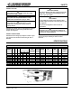
ELECTRICAL AND MECHANICAL INTRODUCTION • This section of the manual contains drawings and schematics of the electrical and mechanical piping systems. The locked rotor amps of a compressor is the current value recorded three seconds after rated voltage is applied under locked rotor conditions from a 75 degree Fahrenheit motor soakout temperature (The voltage drop is to be predetermined and adjusted accordingly prior to testing).
ELECTRICAL AND MECHANICAL Figure 9.
ELECTRICAL AND MECHANICAL Figure 9.
LIMITED WARRANTY INTRODUCTION To Secure Warranty Service 1. To claim a defect under this warranty, direct your claim to whomever you purchased the product. Be prepared to provide the model number, serial number, and a description of the problem. Middleby warrants their cabinets and units to consumers only against defects in material or workmanship under normal use and service for a period of one year from the date of shipment.
NOTES Refrigerated Base-Self-Contained © 2002 28 Printed in USA 12/02