
Refrigerated Base Remote Condenser User Manual

10
Printed in USA 12/02
Refrigerated Base-Remote © 2002
CORRECTIVE MAINTENANCE
INTRODUCTION
This chapter focuses on the instruction needed in the
removal and replacement of certain components. It also
addresses the repair of components not listed under the
scheduled maintenance index covered in the Scheduled
Maintenance section.
The level of skills required to perform the service or repair will
vary. Some may require specific training while others may be
performed by any type of mechanic. It is up to the individual
and his/her supervisor to determine the breadth of knowledge
required to perform the necessary service or to make the
necessary repairs.
It is also important to know that any procedure requiring the
handling of refrigerant requires proper certification.
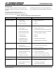
The service or repair items are limited to those parts listed in
Table 7-3.
REPAIR PROCEDURES
7. The final step in removing the compressor is to
disconnect it from its mounting. To free the
compressor, remove the wire clips on each of the four
feet.
8. To install the compressor, place it in position on the
base and reinstall the four wire clips.
9. Reattach the suction and discharge valve blocks to the
appropriate sides of the compressor.
10. Reattach the low-pressure control capillary tube and
service fittings to the suction side of the compressor.
11. Reattach the suction line to the compressor.
12. In reconnecting the high-pressure line, it is necessary
to first prepare the line’s end. Using a fine sandpaper
or emery cloth, clean the residue off of the end. Also,
clean the connection on the compressor. Apply flux to
both ends and braze the connections into place.
13. Remove the valve stem cap from the suction valve
block on the side of the compressor. Run the valve
stem all of the way out and then in one turn clockwise.
14. Place the refrigeration service manifold gauge hoses
on the suction and high-side valves. Attach a bottle of
refrigerant to the charging hose and charge the system
with 150 psi of vapor. Using an electronic leak
detector, check the new connections for leaks. Should
a leak appear, evacuate the charge and repair the leak.
Repeat the leak check process again.
15. If the system checks out with no leaks, recover the test
charge using a vacuum recovery pump.
16. With the system pressure at zero, connect the vacuum
pump and evacuate the system. The pump should run
for one hour. The vacuum pump should pull the
system down to 30 inches of vacuum.
17. Reattach the electrical terminal box and secure all
wiring.
18. Check the refrigeration tag on the unit for the number
of ounces of refrigerant to place into the system for
start-up. Monitor the pressure on both the suction and
discharge sides of the manifold gauges. As the
temperature in the storage area begins to fall, check
the refrigerant flow through the sight glass. The unit is
fully charged when there are no bubbles in the sight
glass. If after five minutes of operation, bubbles are
still present, it may be necessary to add more
refrigerant (add refrigerant in small amount to keep
from overcharging).
WARNING
Prior to performing any work on the refrigeration system,
it is required that the unit be de-energized.
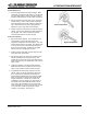
Replacement of Compressor Motor
i
1. Evacuate the refrigerant from the system using a
refrigeration vacuum pump.
NOTE: Federal laws require the proper handling and
disposal of refrigerant. It is unlawful to release any
refrigerant into the atmosphere.
2. Disconnect the electrical power to the unit. This is
done by turning off the circuit in the main supply panel.
It should be noted on the panel that the refrigerator is
being serviced and that the breaker must remain off.
3. Find the electrical terminal box on the side of the
compressor and remove the front cover. Disconnect
the wires from the compressor. Remove the screws
that attach the terminal box to the compressor. At this
point, the compressor will be electrically detached.
4. Using wrenches, remove the suction and discharge
valve stem cover caps on each side of the compressor.
Also, remove the cap nut on the suction and discharge
side as well.
5. Disconnect the high-side line at the compressor. This
is done by heating the brazed connection using an
acetylene and oxygen torch set.
NOTE: Do not apply a flame to a line containing refrigerant.
6. To remove the low-pressure control capillary tube and
service fitting, loosen the 1/4" brass flare nut on the
suction valve.
WARNING
Overcharging a refrigeration system can be dangerous.