IMPORTANT FOR FUTURE REFERENCE Please complete this information and retain this manual for the life of the equipment: Model #: ___________________________ Serial #: ___________________________ Date Purchased: _____________________ Owner’s Manual Ultimate Restaurant Ranges 4365A 4601DD-2RR WARNING Improper installation, adjustment, alteration, service or maintenance can cause property damage, injury or death.
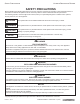
SAFETY PRECAUTIONS ULTIMATE RESTAURANT RANGES SAFETY PRECAUTIONS Before installing and operating this equipment, be sure everyone involved in its operation is fully trained and aware of precautions. Accidents and problems can be caused by failure to follow fundamental rules and precautions. The following symbols, found throughout this manual, alert you to potentially dangerous conditions to the operator, service personnel, or to the equipment.
ULTIMATE RESTAURANT RANGES TABLE OF CONTENTS Congratulations! You have purchased one of the finest pieces of heavy-duty commercial cooking equipment on the market. You will find that your new equipment, like all Southbend equipment, has been designed and manufactured to meet the toughest standards in the industry. Each piece of Southbend equipment is carefully engineered and designs are verified through laboratory tests and field installations.
SPECIFICATIONS ULTIMATE RESTAURANT RANGES SPECIFICATIONS NOTICE Local codes regarding installation vary greatly from one area to another. The National Fire Protection Association, Inc. states in its NFPA 96 latest edition that local codes are the “authority having jurisdiction” when it comes to installation requirements for equipment. Therefore, installations should comply with all local codes. Southbend reserves the right to change specifications and product design without notice.
ULTIMATE RESTAURANT RANGES SPECIFICATIONS GAS SUPPLY The total BTU gas requirement for the range varies depending on the ordered options. The gas requirement and type of gas the range is configured for (natural gas or propane) is stated on the serial plate. A 3/4” female NPT gas connection is located on the rear of the range. The serial plate is located inside the oven kick panel (see Figure 1).
INSTALLATION ULTIMATE RESTAURANT RANGES INSTALLATION NOTICE These installation procedures must be followed by qualified personnel or warranty will be void. Local codes regarding installation vary greatly from one area to another. The National Fire Protection Association, Inc. States in its NFPA 96 latest edition that local codes are the “authority having jurisdiction” when it comes to installation requirements for equipment. Therefore, installations should comply with all local codes.
ULTIMATE RESTAURANT RANGES INSTALLATION STEP 2A: ATTACH LEGS A set of four legs is packed with ranges ordered with legs. (For ranges ordered with casters, go to Step 2b.) A threaded leg pad is fastened to the base frame at each corner. Each leg has a corresponding mating thread. The legs can be adjusted to overcome a slightly uneven floor. 1. Raise range sufficiently to allow legs to be attached.
INSTALLATION ULTIMATE RESTAURANT RANGES A set of four casters is packed with ranges ordered with casters (instead of legs). A threaded leg pad is fastened to the base frame at each corner. Each caster has a corresponding mating thread. The casters can be adjusted to overcome a slightly uneven floor. Casters are provided with a fitting for proper lubrication when required. 1. Raise range sufficiently to allow the casters to be attached.
ULTIMATE RESTAURANT RANGES INSTALLATION 2. Install eye-bolt (item “F”) to a frame member on the rear of the equipment. After checking carefully behind the frame member for adequate clearance, drill a 1/4” (6 mm) hole through the frame member. 3. Thread hex nut (item “G”) and slide the washer (item “H”) onto the eye-bolt. Insert the eye-bolt through the 1/4” (6 mm) drilled hole and secure with a washer (item “H”) and nylon lock nut (item “I”). 4.
INSTALLATION ULTIMATE RESTAURANT RANGES STEP 3: ATTACH FLUE RISER AND SHELF ASSEMBLY Place the flue riser assembly on the range as shown on the appropriate diagram below. 1. Slide the flue riser assembly over the bayonets until it bottoms out, as shown below. 2. Secure ends of flue riser assembly with two (2) 1/4-20 x 3/4 hex head bolts, flat washers and lockwashers. 3. Attach the shelf assembly (if ordered) to the flue riser assembly with 1/4-20 x 3/4 hex head bolts, flat washers and lockwashers.
ULTIMATE RESTAURANT RANGES INSTALLATION The serial plate is located on the interior side of the kick panel below the oven. It indicates the type of gas the range is equipped to burn. All Southbend equipment is adjusted at the factory. Check type of gas on serial plate. These models are design-certified for operation on natural or propane gases. For natural gas, the regulator is set to deliver gas at 0.99 kPa (4” W.C.) pressure to the manifold. For propane gas, it is set to 2.48 kPa (10” W.C.).
OPERATION ULTIMATE RESTAURANT RANGES OPERATION DANGER EXPLOSION HAZARD In the event a gas odor is detected, shut down equipment at the main gas shut-off valve and immediately call the emergency phone number of your gas supplier. Improper ventilation can result in headaches, drowsiness, nausea, and could result in death. Do not obstruct the flow of combustion and ventilation air to and from cooking appliances. CAUTION If top-burner pilots go out, the flow of gas to the burners is NOT interrupted.
ULTIMATE RESTAURANT RANGES OPERATION 5. Light the pilot while continuing to depress the button on the safety valve. Wait 30 seconds, then release the button. The pilot should remain lit. 6. Turn the knob on the safety valve to the ON position. 7. Close the kick panel. 8. Replace the fire plate and oven bottom. OPERATION OF ELECTRIC OVEN To operate an electric oven, do the following: 1. Turn the oven switch on the front panel to ON. 2.
OPERATION ULTIMATE RESTAURANT RANGES To light the pilots of a raised-griddle broiler, do the following: 1. Remove griddle from unit. 2. Position ceramics on burners with projections pointing downward. 3. Light pilot tube ports (2 at each burner). Adjust pilot flame to be large enough to effect ignition. 4. Place griddle in position on range. 5. Turn control knobs completely on. 6. Burner should have 1/2” to 5/8” steady blue flame. Adjust if necessary.
ULTIMATE RESTAURANT RANGES OPERATION WARNING THE USE OF ALUMINUM FOIL CAN CAUSE HEAT DISTRIBUTION PROBLEMS IN OVENS. EXTREME CARE MUST BE USED WHEN PLACING ALUMINUM FOIL IN THE OVEN TO ENSURE THAT IT DOES NOT BLOCK OR CHANGE THE AIR FLOW. THE USE OF ALUMINUM FOIL MAY VOID THE PRODUCT WARRANTY IF ITS USE IS ASCERTAINED TO BE A PROBLEM.
CLEANING ULTIMATE RESTAURANT RANGES CLEANING WARNING Shut off the range and allow time for it to cool before cleaning or performing maintenance. Southbend appliances are sturdily constructed of the best materials and are designed to provide durable service when treated with ordinary care. To expect the best performance, your equipment must be maintained in good condition and cleaned daily. Naturally, the periods for this care and cleaning depend on the amount and degree of usage.
ULTIMATE RESTAURANT RANGES CLEANING Soil and burnt deposits which do not respond to the above procedure can usually be removed by rubbing the surface with SCOTCH-BRITE scouring pads or STAINLESS scouring pads. DO NOT USE ORDINARY STEEL WOOL as any particles left on the surface will rust and further spoil the appearance of the finish. NEVER USE A WIRE BRUSH, STEEL SCOURING PADS (EXCEPT STAINLESS), SCRAPER, FILE OR OTHER STEEL TOOLS.
ADJUSTMENTS ULTIMATE RESTAURANT RANGES ADJUSTMENTS WARNING ADJUSTMENTS AND SERVICE WORK MAY BE PERFORMED ONLY BY A QUALIFIED TECHNICIAN WHO IS EXPERIENCED IN, AND KNOWLEDGEABLE WITH, THE OPERATION OF COMMERCIAL COOKING EQUIPMENT. HOWEVER, TO ASSURE YOUR CONFIDENCE, CONTACT YOUR AUTHORIZED SERVICE AGENCY FOR RELIABLE SERVICE, DEPENDABLE ADVICE OR OTHER ASSISTANCE, AND FOR GENUINE FACTORY PARTS.
ULTIMATE RESTAURANT RANGES ADJUSTMENTS ADJUSTMENT OF OPEN-TOP BURNERS All open-top burners are primarily adjusted by means of an air shutter on the mixer face. To adjust a burner, loosen the screw that holds the air shutter in position and rotate the mixer cap until a clear, stable blue flame is obtained. The flame should not be yellow tipped nor should it blow off the burner ports. All orifice sizes and burner rate are properly set at the factory and should not be altered.
ADJUSTMENTS ULTIMATE RESTAURANT RANGES The control should be re-calibrated if your reading is not within 20 degrees of the dial setting (350°F). If calibration is required, the additional steps to be taken are these: 4. Insert a flat screwdriver through the center of the thermostat stem and then turn the adjustment screw clockwise to decrease the oven temperature and counterclockwise to increase the oven temperature. Do not allow the stem to turn.
ULTIMATE RESTAURANT RANGES ADJUSTMENTS Figure 11 Thermostat Calibration and Bypass Flame Adjustment Bypass Adjuster Calibration Stem Bezel Dial Insert Dial CONVERSION FROM ONE TYPE OF GAS TO ANOTHER Each range is shipped adjusted and equipped for a specific type of gas (either natural gas or propane). To convert a range from one type of gas to another, do the following: 1. Refer to service procedures to access all burner orifices. 2. Refer to instructions included with conversion kit. 3.
TROUBLESHOOTING ULTIMATE RESTAURANT RANGES TROUBLESHOOTING WARNING ADJUSTMENTS AND SERVICE WORK MAY BE PERFORMED ONLY BY A QUALIFIED TECHNICIAN WHO IS EXPERIENCED IN, AND KNOWLEDGEABLE WITH, THE OPERATION OF COMMERCIAL COOKING EQUIPMENT. HOWEVER, TO ASSURE YOUR CONFIDENCE, CONTACT YOUR AUTHORIZED SERVICE AGENCY FOR RELIABLE SERVICE, DEPENDABLE ADVICE OR OTHER ASSISTANCE, AND FOR GENUINE FACTORY PARTS.
ULTIMATE RESTAURANT RANGES TROUBLESHOOTING TROUBLESHOOTING OPEN-TOP BURNERS Each open-top burner should have a steady blue flame on each port of the burner. Propane burners may have a small amount of yellow tipping, and may make a slight popping noise when turned off. If the flame is rising up off of the ports, adjust the burner shutter so it is more closed. If the flame is long and yellow adjust the burner shutter so it is more open. Consult the following table and the flowchart on this page.
TROUBLESHOOTING ULTIMATE RESTAURANT RANGES TROUBLESHOOTING BASE OVEN CAUTION Proper and efficient operation of oven is dependent on correct installation and function of components. Always verify that components are in place and functioning as intended. Consult the following table and the flowchart that begins on the following page. Problem Look for - Oven will not come on. – Oven pilot is out. Oven pilot will not stay ignited – Pilot gas not adjusted properly. – Bad thermopile.
ULTIMATE RESTAURANT RANGES TROUBLESHOOTING TROUBLESHOOTING CONVECTION-OVEN BLOWER WARNING Before attempting to service or replace any electrical component, make sure power source has been disconnected. CAUTION When changing motor or servicing range, always verify that blower wheel rotation is clockwise when looking into the oven cavity. If the blower does not run at all, consult the flowchart that begins on the next page. If the blower runs intermittently, consult the flowchart on this page.
TROUBLESHOOTING ULTIMATE RESTAURANT RANGES Figure 9 Convection-Oven Blower Does Not Run Convection-oven blower does not run. DISCONNECT POWER AT CIRCUIT BREAKER. Remove the control knobs from the front of the range. Remove the screws that secure the top of the control panel and carefully tilt the panel forward to expose the back of the blower switch that is mounted in the front panel. CAUTION: Be careful not to damage the wiring behind the control panel.
ULTIMATE RESTAURANT RANGES TROUBLESHOOTING Figure 10 Convection-Oven Blower Does Not Run, Continued (Continuing from previous page.) CHECK THAT POWER IS DISCONNECTED AT CIRCUIT BREAKER. Remove the wire terminal cover from the blower motor. Check that the red wire is capped off. Remove the wire nuts from the black and the white wires. Check that in each case the wires are twisted together securely. Check that the common wire is connected to the motor black wire.
TROUBLESHOOTING ULTIMATE RESTAURANT RANGES Figure 12 Wiring Diagram for Gas Oven PAGE 28 OF 34 OWNER’S MANUAL 1190820 REV 4 (10/14)
ULTIMATE RESTAURANT RANGES TROUBLESHOOTING Figure 13 Wiring Diagram for Electric Standard Oven OWNER’S MANUAL 1190820 REV 4 (10/14) PAGE 29 OF 34
TROUBLESHOOTING ULTIMATE RESTAURANT RANGES Figure 14 Wiring Diagram for Electric Convection Oven PAGE 30 OF 34 OWNER’S MANUAL 1190820 REV 4 (10/14)
ULTIMATE RESTAURANT RANGES Notes: OWNER’S MANUAL 1190820 REV 4 (10/14) PAGE 31 OF 34
ULTIMATE RESTAURANT RANGES Notes: PAGE 32 OF 34 OWNER’S MANUAL 1190820 REV 4 (10/14)
ULTIMATE RESTAURANT RANGES Notes: OWNER’S MANUAL 1190820 REV 4 (10/14) PAGE 33 OF 34
ULTIMATE RESTAURANT RANGES Ultimate Restaurant Ranges A product with the Southbend name incorporates the best in durability and low maintenance. We all recognize, however, that replacement parts and occasional professional service may be necessary to extend the useful life of this appliance. When service is needed, contact a Southbend Authorized Service Agency, or your dealer. To avoid confusion, always refer to the model number, serial number, and type of your appliance.