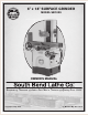
6" x 18" SURFACE GRINDER MODEL SB1029 OWNER'S MANUAL Hundreds of Thousands of Lathes Sold With a Tradition of Q uality Since 1906! Copyright © May, 2010 For Machines Mfg.
Scope of Manual This manual helps the reader understand the machine, how to prepare it for operation, how to control it during operation, and how to keep it in good working condition. We assume the reader has a basic understanding of how to operate this type of machine, but that the reader is not familiar with the controls and adjustments of this specific model. As with all machinery of this nature, learning the nuances of operation is a process that happens through training and experience.
Table of Contents INTRODUCTION ...............................................................2 About This Machine ............................................. 2 Capabilities ......................................................... 2 Features .............................................................. 2 Identification ........................................................ 3 Machine Specifications ........................................ 4 SAFETY..........................................................
Model SB1029 INTRODUCTION For Machines Mfg. Since 8/09 INTRODUCTION About This Machine Capabilities Features This 6 x 18" Surface Grinder allows you to smooth the surface of metallic workpieces. It utilizes a table that moves on a horizontal plane and a grinding wheel that moves along a vertical axis. By mounting a workpiece to the table, then moving the table and the grinding wheel during the grinding process, extremely small amounts of material can be removed to create high-tolerance flat surfaces.
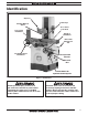
For Machines Mfg. Since 8/09 INTRODUCTION Model SB1029 Identification Chip Port Travel Stops Grinding Wheel & Guard Cross Travel Lock Knob Cross Travel Handwheel Elevation Handwheel Removable Lifting Hooks (x4) Longitudinal Travel Handwheel Operation Controls Electrical Box Coolant Switch for Optional Coolant System Figure 1. Identification. Serious personal injury could occur if you connect the machine to power before completing the setup process.
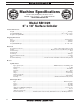
Model SB1029 INTRODUCTION For Machines Mfg. Since 8/09 Machine Specifications Machine Specifications P.O. Box 2027, Bellingham, WA 98227 U.S.A. 0(/.% s © South Bend Lathe Co. www.southbendlathe.com Model SB1029 6" x 18" Surface Grinder Product Dimensions: Weight ........................................................................................................................................................................1912 lbs. Length/Width/Height .................................
For Machines Mfg. Since 8/09 INTRODUCTION Model SB1029 Main Specifications: Operation Information Maximum Distance Wheel To Table...................................................................................................................... 15 5⁄8" Maximum Distance Table To Spindle Center ...................................................................................................... 193⁄16" Long Stroke .........................................................................................
Model SB1029 SAFETY For Machines Mfg. Since 8/09 SAFETY Understanding Risks of Machinery Operating all machinery and machining equipment can be dangerous or relatively safe depending on how it is installed and maintained, and the operator's experience, common sense, risk awareness, working conditions, and use of personal protective equipment (safety glasses, respirators, etc.). The owner of this machinery or equipment is ultimately responsible for its safe use.
For Machines Mfg. Since 8/09 SAFETY Model SB1029 5. Entanglement: Loose clothing, gloves, neckties, jewelry or long hair may get caught in moving parts, causing entanglement, amputation, crushing, or strangulation. Reduce this risk by removing/securing these items so they cannot contact moving parts. 11. Chuck Keys or Adjusting Tools: Tools used to adjust spindles, chucks, or any moving/ rotating parts will become dangerous projectiles if left in place when the machine is started.
Model SB1029 SAFETY For Machines Mfg. Since 8/09 Additional Surface Grinder Safety 1. 2. 3. Eye Protection: Grinding causes small particles to become airborne at a high rate of speed creating a risk of eye injury. ALWAYS wear eye protection when using this machine. Wheel Speed Rating: Wheels operated at a faster speed than they are rated for may break or fly apart and impact the operator or bystanders.
For Machines Mfg. Since 8/09 P R E PA R AT I O N Model SB1029 PREPARATION Preparation Overview Things You'll Need The list below outlines the basic process to follow to prepare your machine for operation. Specific steps for each of these points will be covered in detail later in this section.
P R E PA R AT I O N Model SB1029 Power Supply Requirements Availability Before installing the machine, consider the availability and proximity of the required power supply circuit. If an existing circuit does not meet the requirements for this machine, a new circuit must be installed. To minimize the risk of electrocution, fire, or equipment damage, installation work and electrical wiring must be done by a qualified electrician in accordance with all applicable codes and standards.
P R E PA R AT I O N For Machines Mfg. Since 8/09 Model SB1029 Grounding Requirements In the event of certain types of malfunctions or breakdowns, grounding provides a path of least resistance for electric current—in order to reduce the risk of electric shock. Serious injury could occur if you connect the machine to power before completing the setup process. DO NOT connect to power until instructed later in this manual.
Model SB1029 P R E PA R AT I O N For Machines Mfg. Since 8/09 Unpacking This item was carefully packaged to prevent damage during transport. If you discover any damage, please immediately call Customer Service at (360) 734-1540 for advice. You may need to file a freight claim, so save the containers and all packing materials for possible inspection by the carrier or its agent. A Inventory B Main Inventory 1: (See Figure 4) Qty A. Surface Grinder (Wheel Installed) ................
For Machines Mfg. Since 8/09 P R E PA R AT I O N Model SB1029 Cleaning & Protecting The unpainted surfaces are coated at the factory with a heavy-duty rust preventative that prevents corrosion during shipment and storage. The benefit of this rust preventative is that it works very well. The downside is that it can be time-consuming to thoroughly remove. Be patient and do a careful job when cleaning and removing the rust preventative.
P R E PA R AT I O N Model SB1029 For Machines Mfg. Since 8/09 Weight Load Location Physical Environment The physical environment where your machine is operated is important for safe operation and longevity of parts. For best results, operate this machine in a dry environment that is free from excessive moisture, hazardous or flammable chemicals, airborne abrasives, or extreme conditions.
For Machines Mfg. Since 8/09 P R E PA R AT I O N Lifting & Moving This machine and its parts are heavy! Serious personal injury may occur if safe moving methods are not used. To reduce the risk of a lifting or dropping injury, ask others for help and use power equipment. Unbolt the machine from the pallet and make sure that the table is locked in place.
P R E PA R AT I O N Model SB1029 Bolting to Concrete Floors Lag screws and anchors, or anchor studs (below), are two popular methods for securing machinery to a concrete floor. We suggest you research the many options and methods for securing your machine and choose the best one for your specific application. Assembly If you desire to use the mounting feet included with your machine, proceed as follows. To assemble the machine: 1.
For Machines Mfg. Since 8/09 6. P R E PA R AT I O N Model SB1029 Locate the flat shown in Figure 11 on the headstock elevation handwheel shaft Next align the set screw on the elevation handwheel hub with the flat on the shaft, and slide the handwheel (see Figure 12) onto the shaft until it stops. Cap Screw Flat Wires Figure 13. Neoprene shipping seat wires. Figure 11. Headstock elevation handwheel. 7.
Model SB1029 P R E PA R AT I O N Power Connection Electrocution or fire may occur if machine is ungrounded, incorrectly connected to power, or connected to an undersized circuit. Use a qualified electrician to ensure a safe power connection. Initial Lubrication Your machine was lubricated at the factory, but we strongly recommend that you inspect all lubrication points yourself and provide additional lubrication if necessary.
For Machines Mfg. Since 8/09 P R E PA R AT I O N Test Run 6. Refer to Troubleshooting on Page 36 for solutions to common problems that may occur with surface grinders. If you need additional help, contact our Technical Support at (360) 7341540. Read and follow the safety instructions at the beginning of the manual, take the required safety precautions, and make sure the machine is set up and adjusted properly. 3. Clear away all tools and objects used during assembly and preparation. 4.
Model SB1029 O P E R AT I O N OPERATION For Machines Mfg. Since 8/09 Operation Overview To complete a typical operation, the operator does the following: The purpose of this overview is to provide the novice machine operator with a basic understanding of how the machine is used during operation, so they can more easily understand the controls discussed later in this manual. 1. Examines the grinding wheel to make sure it is suitable for use (has no visible cracks or large chips). 2.
For Machines Mfg. Since 8/09 O P E R AT I O N Model SB1029 Controls G. Power Indicator Light: Illuminates when the grinding wheel motor is running. Refer to Figures 16–18 and the following descriptions to become familiar with the basic controls of this machine. H. Power On Button: Supplies power to the grinding wheel motor. I. Emergency Stop (Off) Button: Cuts power to the grinding wheel motor. J. Coolant Pump Switch: Control switch for the optional coolant pump accessory. A.
O P E R AT I O N Model SB1029 Grit Size Wheel Selection Most grinding wheels from major manufacturers are marked in a somewhat uniform manner. Understanding these markings will help you understand the capabilities of various wheels. Always refer to the manufacturer’s grinding recommendations when selecting a wheel for your project. The grinding wheel you choose will depend on several factors related to the operation you plan to perform.
For Machines Mfg. Since 8/09 O P E R AT I O N Model SB1029 Wheel Inspection Ring Test Do not assume that a wheel is in sound condition just because it is new—damage can often occur during shipping, with age, with prolonged exposure to moisture, or because of improper storage. This test will give you an indication of any internal damage that may not be obvious during a visual inspection. To inspect a wheel for damage: 1.
O P E R AT I O N Model SB1029 Removing & Installing Grinding Wheels 4. For Machines Mfg. Since 8/09 Using the wrenches, loosen the retaining nut in the direction shown in Figure 23. ! If installing a grinding wheel for the first time, or when replacing a worn wheel, this section explains the order in which this process must take place. Every time a grinding wheel is removed from its hub, this procedure must be repeated.
For Machines Mfg. Since 8/09 7. O P E R AT I O N Wipe the grinding wheel seat shown in Figure 26, so it is perfectly clean, and no paper is left behind. Note: A slight wiping of the spindle threads, grinding wheel seat, and hub with a lightlyoiled rag is acceptable to prevent rust. ! Note: If you need to replace or install new paper washers, replacements can be cut out of any thick construction paper or card stock.
O P E R AT I O N Model SB1029 Removing & Installing Wheel & Hub 4. For Machines Mfg. Since 8/09 Loosen the barrel nut in the direction shown in Figure 30. ! The procedure in this section describes how to install or swap one or more pre-balanced grinding wheel and hub assemblies. Having a selection of pre-balanced grinding wheel and hub assemblies on the shelf ready to go increases productivity if different grinding wheel profiles must be use during a grinding project.
For Machines Mfg. Since 8/09 7. O P E R AT I O N While holding the wheel and hub from sliding off of the spindle, use the wrenches shown in Figure 33, tighten the hub puller until the wheel and hub assembly is pulled from the spindle. Model SB1029 Spindle Taper ! Threads Hold Figure 35. Spindle taper. Hub Taper Figure 33. Pulling wheel hub. 8. Set the wrenches aside and carefully remove the wheel and hub assembly with the hub puller still installed (see Figure 34). ! Figure 36. Wheel hub taper.
O P E R AT I O N Model SB1029 For Machines Mfg. Since 8/09 To dress the grinding wheel: Wheel Dressing 1. Superior grinding results can only be achieved with a properly balanced and dressed wheel. Do not assume that a wheel will run true on the spindle if it is new or has not been separated from the hub. Insert the diamond-tipped dressing tool into its base (see Figure 38), and use a 4mm hex wrench to tighten the locking set screw.
For Machines Mfg. Since 8/09 O P E R AT I O N Wheel Balancing 4. Static wheel balancing can be difficult and very time consuming without practice. For accurate grinding results, wheel balancing is mandatory. For this balancing procedure, you will need a wheel balancing fixture. The wheel balancing fixture shown in Figure 39 is one example of the many varieties available on the market. Before proceeding, the grinding wheel must be ring tested (refer to Page 23) and dressed (refer to Page 28).
Model SB1029 O P E R AT I O N 7. Spin the wheel so it rotates one full turn and comes to rest with the heaviest side hanging down at six O'clock. This may take a few times to find the exact location. 8. Using a pencil, draw a line on the wheel at the six O'clock position to mark the heaviest side. 9. Line up the closest dog with the line you just drew and lock it in place. This dog will now be positioned at the heaviest side of the wheel and will be called dog "A". 10.
For Machines Mfg. Since 8/09 O P E R AT I O N Magnetic Chuck The Model SB1029 table is equipped with a T-slot for securing a magnetic chuck. Refer to the magnetic chuck manufacturer's instruction manual for proper preparation and mounting techniques. A magnetic chuck secures workpieces to the table without the use of clamps. With proper attention to preparation of both the workpiece and the magnetic chuck, a magnetic chuck will provide ample clamping force on most magnetic metals.
Model SB1029 O P E R AT I O N Using the Surface Grinder Operation of the grinder is controlled through the movement of the three handwheels. The elevation handwheel controls the up and down movement of the grinding head. It is this axis that governs the amount of stock removal. Never attempt to remove too much material in one pass. The best results are achieved with multiple light passes. The longitudinal travel handwheel rapidly moves the table from left to right.
For Machines Mfg. Since 8/09 MAINTENANCE Model SB1029 MAINTENANCE Maintenance Schedule Basic Lubrication ! Always disconnect machine from power before performing maintenance or serious personal injury may result. Recommended Lubricating Oil Types: To avoid oil breakdown, DO NOT MIX OILS! If changing oil types, be sure to flush system with the new oil and discard the flushed oil.
Model SB1029 MAINTENANCE — If the pinions or leadscrew show a buildup of contaminants, clean them with mineral spirits and re-oil. — If the pinions or leadscrew are dry, verify that the pump screen is clean, and adjust the oil distribution screw to increase lubrication. 4. At the rear of the column, slide the column dust shield upward and inspect the upper leadscrew (see Figure 46). For Machines Mfg.
For Machines Mfg. Since 8/09 MAINTENANCE 4. Close needle valve #4 (see Figure 47), and then open it three full turns. 5. Place a waste oil container under the dump line (see Figure 47), and turn the pump on. The waste oil will be pumped into the waste oil container. When the reservoir is empty, wipe the reservoir out with clean rags. 6. Using a 4mm hex wrench, remove the pump mounting screws and the pump. 7. Invert the pump and inspect the suction screen (see Figure 48).
TROU B LESHOOTI NG Model SB1029 For Machines Mfg. Since 8/09 TROUBLESHOOTING If you need replacement parts, or if you are unsure how to do any of the solutions given here, feel free to call us at (360) 734-1540. Symptom Machine does not start. Possible Cause Possible Solution 1. No power; voltage is incorrect. 1. Switch power supply ON/verify and correct voltage. 2. Blown fuse/tripped circuit breaker at main panel. 2. Correct the cause of overload, then reset/replace fuse or breaker. 3.
For Machines Mfg. Since 8/09 Symptom Vibration when grinding, poor surface finish, or incorrect final dimensions. TROU B LESHOOTI NG Model SB1029 Possible Cause Possible Solution 1. Grinding wheel is out-of-round or is loaded up with material. 1. Dress grinding wheel to make concentric, and to the required grit level (Page 28). 2. Grinding wheel is out of balance or damaged. 2. Remove and ring test (Page 23), and balance the grinding wheel (Page 29). 3. Missing or torn grinding wheel paper washers.
Model SB1029 SERVICE For Machines Mfg. Since 8/09 service Machine Storage If the machine is not properly prepared for storage, it may develop rust or corrosion. If decommissioning this machine, use the steps in this section to ensure that it remains in good condition for later use. To prepare your machine for storage: 1. Pump out the old oil, then clean and wipe out the oil reservoir. 2. If coolant was used, put on safety goggles and clean the coolant system.
For Machines Mfg. Since 8/09 ELECTRICAL Model SB1029 ELECTRICAL Electrical Safety Instructions These pages are accurate at the time of printing. In the constant effort to improve, however, we may make changes to the electrical systems of future machines. Study this section carefully. If you see differences between your machine and what is shown in this section, call Technical Support at (360) 734-1540 for assistance BEFORE making any changes to the wiring on your machine. 1.
W T V T S U S R 0 V1 U1 V1 W1 R W1 W U1 V V U W 0 0 7 For Machines Mfg. Since 8/09 U Wiring diagrams are provided in this section showing the Model SB1029 wired for both 220V and 440V. Refer to these diagrams if needed when following this procedure. Additionally, you must purchase 440V Conversion Kit (Part No. PSB1029510) in order to complete the conversion.
ELECTRICAL For Machines Mfg. Since 8/09 3. Without changing the location of any of the wires, reposition the jumpers as shown in Figure 54. Stack the jumpers as needed, since there will be two extras. 6. Replace the installed relays for the coolant pump relay and spindle motor with the relays from the 440V conversion kit, installing all of the wires in the same location from which they were removed. 7.
ELECTRICAL Model SB1029 For Machines Mfg. Since 8/09 220V Electrical Components ! ! Spindle Motor Fig. 58. Electrical box & control panel location. NO Oil Pump Motor 3 3 3 3 4 X1 X2 R EWO P X1 0 1 X2 2 2 0 0 Figure 57. Spindle motor & pump motor locations.
ELECTRICAL For Machines Mfg. Since 8/09 Model SB1029 220V Electrical Box 3 8 4 9 T R 1 2 3 4 R S 1 R T 3 5 L1 T 3 L2 5 L3 7 3 R L4 1 R S L1 CONTACTOR Allen Bradley C09400 0 208 220 440 480 Transformer LCP-TBS 2 T1 4 T2 3 S T T L2 5 L3 7 L4 CONTACTOR Allen Bradley C09400 6 T3 8 T4 2 T1 4 T2 6 T3 8 T4 0 12 24 0 110 T1 R1 0 1 AMP 1 2 3 6 4 95 NC O AMP THERMAL RELAY 5 4 1.
ELECTRICAL Model SB1029 For Machines Mfg. Since 8/09 440V Electrical Components ! ! Spindle Motor Figure 60. Electrical box & control panel location. NO Oil Pump Motor 3 3 3 3 4 X1 X2 R EWO P X1 0 1 X2 2 2 0 0 Figure 59. Spindle motor & pump motor locations.
ELECTRICAL For Machines Mfg. Since 8/09 Model SB1029 Electrical Box For 440V: "T" Positioned at 440V 3 8 4 9 T R 1 2 3 4 R S 1 R L1 T 0 208 220 440 480 For 440V: Set at 0.25A 0 12 24 0 110 R1 1 2 0 3 4 3 3 L2 5 L3 7 3 R L4 1 R S S T T L1 L2 5 L3 CONTACTOR Allen Bradley C09400 Transformer LCP-TBS T1 T 5 2 T1 1 4 T2 6 T3 AMP 1.6 For 440V: Set at 2.4A 5 8 T4 2 T1 THERMAL RELAY 2.4 3 7 L4 CONTACTOR Allen Bradley C09400 0.1 4 T2 AMP 0.
PARTS Model SB1029 For Machines Mfg.
PARTS For Machines Mfg.
PARTS Model SB1029 For Machines Mfg. Since 8/09 Table 121 125 113 109 125 108 107 101 110 106 111 124 123 126 110 123 111 103 105 102 112 108 109 122 105 127 104 REF PART # DESCRIPTION REF PART # DESCRIPTION 101 102 103 104 105 106 107 108 109 110 TABLE FRONT RAIL REAR RAIL LEFT CABLE SPOOL CABLE PULLEY COLLAR WIPER FIXED PLATE RUBBER PLATE FIXED PLATE SQUARE NUT M8-1.
PARTS For Machines Mfg.
PARTS Model SB1029 For Machines Mfg.
For Machines Mfg.
PARTS Model SB1029 For Machines Mfg. Since 8/09 Tools 401 408 403 402 412 409 404 405 406 413 411 410 407 REF PART # DESCRIPTION REF PART # DESCRIPTION 401 402 403 404 405 406 407 PSB1029401 PSB1029402 PSB1029403 PSB1029404 PSB1029405 PW01 PN41 TOOL BOX DRESSING TOOL BASE DIAMOND-TIP DRESSER HUB PULLER T-BOLT 1/2-12 x 2 FLAT WASHER 1/2 HEX NUT 1/2-12 408 409 410 411 412 413 PSDF2 PAW1510M PSB1029410 PSB1029411 PSB1029412 PSB1029413 SCREWDRIVER FLAT #2 HEX WRENCH SET 10PC 1.
PARTS For Machines Mfg. Since 8/09 Model SB1029 Electrical 501 1 2 3 4 503 502 5 1 L1 3 L2 5 L3 7 L4 1 L1 CONTACTOR Allen Bradley C09400 0 208 220 440 480 Transformer LCP-TBS 2 T1 4 T2 3 L2 5 L3 7 L4 CONTACTOR Allen Bradley C09400 6 T3 8 T4 2 T1 4 T2 6 T3 8 T4 0 12 24 0 110 AMP 1.6 1 2 3 4 2.4 THERMAL RELAY 0.1 AMP THERMAL RELAY 0.25 0.
PARTS Model SB1029 For Machines Mfg. Since 8/09 Machine Labels 301 MODEL SB1029 6" x 18" SURFACE GRINDER Serial No: MFG Date: ! WARNING! TO REDUCE THE RISK OF SERIOUS PERSONAL INJURY WHILE USING THIS MACHINE: Motor: 1-1/2 HP, 220V/440V, 3-Phase Table Surface Size: 5-3/4" X 18" Spindle Speed: 3450 RPM Longitudinal Travel: 18-7/8" Cross Travel: 6-15/16" Max. Distance Wheel To Table: 15.3" Maximum Grinding Length: 18-1/2" Maximum Grinding Width: 6-15/16" Ver tical Handwheel Revolution: 0.
For Machines Mfg. Since 8/09 PARTS Model SB1029 Machine Labels List REF PART # DESCRIPTION REF PART # DESCRIPTION 301 302 303 304 305 306 307 310 311 312 313 314 MACHINE ID LABEL BEST GRINDING RESULTS LABEL TABLE TIP WARNING LABEL ELECTRICITY LABEL 1.4 CHECK LUBRICANT LABEL MANIFOLD ADJUSTMENT LABEL BIOHAZARD LABEL 3.25 X 2 CABLE DRIVE ADJUSTMENT LABEL 220V 3-PH LABEL DISC POWER LABEL 2 X 3.25 ELECTRICITY LABEL 1.4 READ MANUAL LABEL 2 X 3.
Model SB1029 -56- NOTES For Machines Mfg.
For Machines Mfg. Since 8/09 WAR R ANT Y Model SB1029 WARRANTY & RETURNS This quality product is warranted by South Bend Lathe Company to the original buyer for one year from the date of purchase. This warranty does not apply to consumable parts, or defects due to any kind of misuse, abuse, negligence, accidents, repairs, alterations or lack of maintenance. We do not reimburse for third party repairs.
South Bend Lathe Co. P.O. Box 2027 Bellingham, WA 98227 PHONE: (360) 734-1540 (Administrative Offices) FAX: (360) 676-1075 (International) FAX: (360) 734-1639 (USA only) southbendlathe.