IMPORTANT FOR FUTURE REFERENCE Please complete this information and retain this manual for the life of the equipment: Model #: ___________________________ Serial #: ___________________________ Date Purchased: _____________________ Owner’s Manual G-Series, SL-Series & B-Series GAS CONVECTION OVENS Model GS/15SC Model GS/25SC WARNING Improper installation, adjustment, alteration, service or maintenance can cause property damage, injury or death.
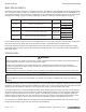
SAFETY PRECAUTIONS GAS CONVECTION OVENS SAFETY PRECAUTIONS Before installing and operating this equipment, be sure everyone involved in its operation is fully trained and aware of precautions. Accidents and problems can be caused by failure to follow fundamental rules and precautions. The following symbols, found throughout this manual, alert you to potentially dangerous conditions to the operator, service personnel, or to the equipment.
GAS CONVECTION OVENS INTRODUCTION Congratulations! You have purchased one of the finest pieces of heavy-duty commercial cooking equipment on the market. You will find that your new equipment, like all Southbend equipment, has been designed and manufactured to meet the toughest standards in the industry. Each piece of Southbend equipment is carefully engineered and designs are verified through laboratory tests and field installations.
SPECIFICATIONS GAS CONVECTION OVENS SPECIFICATIONS NOTICE Local codes regarding installation vary greatly from one area to another. The National Fire Protection Association, Inc. states in its NFPA 96 latest edition that local codes are the “authority having jurisdiction” when it comes to installation requirements for equipment. Therefore, installations should comply with all local codes. Southbend reserves the right to change specifications and product design without notice.
GAS CONVECTION OVENS SPECIFICATIONS If applicable, the vent line from the gas appliance pressure regulator shall be installed to the outdoors in accordance with local codes, or in the absence of local codes, with the National Fuel Gas Code, ANSI Z223.1, Natural Gas Installation Code, CAN/CGA-B149.1, or the Propane Installation Code CAN/CGA-B149.2, as applicable. This appliance should be connected ONLY to the type of gas for which it is equipped.
SPECIFICATIONS GAS CONVECTION OVENS ELECTRICAL SUPPLY Convection ovens require connection to a supply of electricity. The appliance, when installed, must be electrically grounded in accordance with local codes, or in the absence of local codes, with the National Electrical Code, ANSI/NFPA 70, or the Canadian Electrical Code, CSA C22.2, as applicable. An electrical diagram is located on the side of the control panel assembly (see drawing on page 37).
GAS CONVECTION OVENS INSTALLATION INSTALLATION NOTICE These installation procedures must be followed by qualified personnel or warranty will be void. Local codes regarding installation vary greatly from one area to another. The National Fire Protection Association, Inc. states in its NFPA 96 latest edition that local codes are the “authority having jurisdiction” when it comes to installation requirements for equipment. Therefore, installations should comply with all local codes.
INSTALLATION GAS CONVECTION OVENS STEP 2A: INSTALLATION OF LEGS ON SINGLE-DECK-OVENS 1. Raise oven sufficiently to allow clearance for the legs to be attached. Use of a lift truck or other mechanical lifting means is recommended. For safety, “shore up” and support the oven with an adequate blocking arrangement strong enough to support the load. (If it is absolutely necessary to rest the oven on its side, rest it on its left side or back side.
GAS CONVECTION OVENS INSTALLATION STEP 2B: INSTALLATION OF LEGS ON DOUBLE-DECK-OVENS Double-deck oven can be shipped either already bolted together, or as two separate ovens to be bolted together after delivery. In either case, the oven that is (or will be) the lower oven will have leg pads already bolted to the bottom corners of the oven. Do the following: 1. Raise oven sufficiently to allow clearance for the legs to be attached. Use of a lift truck or other mechanical lifting means is recommended.
INSTALLATION GAS CONVECTION OVENS STEP 3: INSTALLATION OF RESTRAINT (ONLY FOR OVENS WITH CASTERS) NOTICE For an appliance equipped with casters, (1) the installation shall be made with a connector that complies with the Standard for Connectors for Movable Gas Appliances, ANSI Z21.69 or Connectors for Moveable Gas Appliances, CAN/CGA-6.16, and a quick-disconnect device that complies with the Standard for Quick-Disconnect Devices for Use With Gas Fuel, ANSI Z21.
GAS CONVECTION OVENS INSTALLATION 2. Install eye-bolt (item “F”) to a frame member on the rear of the equipment. After checking carefully behind the frame member for adequate clearance, drill a 1/4” hole through the frame member. 3. Thread hex nut (item “G”) and slide the washer (item “H”) onto the eye-bolt. Insert the eye-bolt through the 1/4” drilled hole and secure with a washer (item “H”) and nylon lock nut (item “I”). 4.
INSTALLATION GAS CONVECTION OVENS 5. Lift the top oven and position it on top of the lower oven, as shown in the drawing below. 6. Move to the rear of the ovens and remove the six screws shown as items “A” in the left-hand drawing below. Position the tie bracket (item “B”) as shown in the right-hand drawing below. Re-insert the screws that you just removed through the holes in the tie bracket, but do not tighten them yet.
GAS CONVECTION OVENS INSTALLATION 7. Insert two bolts (items “A” in the following diagram) up through the top of the lower oven and screw them into the threaded holes in the bottom of the top oven. Tighten these bolts and the screws that you did not tightened in the previous step. A 8. Assemble the gas piping shown in the following drawing. Be sure to check all connections for leaks once the oven has been installed.
INSTALLATION GAS CONVECTION OVENS 9. Install the flue stack as shown in the following diagram: FLUE STACK 10. Replace the right side insulation, exterior panel, and lower front panel that you removed in step 4 of this procedure.
GAS CONVECTION OVENS INSTALLATION STEP 5: INSTALL DOWN DRAFT DIVERTER (IF APPLICABLE) NOTICE Installation must use approved CSA International down draft diverter supplied by Southbend. If the oven flue is to be connected directly to an external vent, a down draft diverter must be installed. The installation of ventilation pipes through walls and roofs must conform to all local codes. To install the down draft diverter, do the following: 1.
INSTALLATION GAS CONVECTION OVENS STEP 6: INSTALLATION OF OPEN PAN STORAGE ON G & SL SERIES OVENS (OPTIONAL) The following describes how to assemble the optional open pan storage for G-Series and SL-Series ovens. All holes are pre-drilled for the provided screws. 1. Attach the legs to the oven as described in installation Step 2a. 2. Attach the two frame hangers (items “A” in the following drawing). The flanged side of each hanger must be on the side of the hanger closest to the edge of the oven.
GAS CONVECTION OVENS INSTALLATION 4. Hang the two pan guides from the frame hangers. The guides cannot be inserted from the side of the oven because the legs are in the way. Instead, begin by holding the guide parallel to the side of the oven with the horizontal bars of the guide extending inward (so tat the pans can rest on them). Insert the guide from in front of the oven.
INSTALLATION GAS CONVECTION OVENS STEP 7: CONNECT ELECTRICITY SUPPLY WARNING ELECTRIC GROUNDING INSTRUCTIONS This appliance (120V ovens only) is equipped with a three-prong (grounding) plug for your protection against shock hazard and should be plugged directly into a properly grounded three-prong receptacle. Do not cut or remove the grounding prong from this plug..
GAS CONVECTION OVENS INSTALLATION STEP 8: CONNECT GAS SUPPLY NOTICE The installation must conform with local codes, or in the absence of local codes, with the National Fuel Gas Code, ANSI Z223.1, Natural Gas Installation Code, CAN/CGA-B149.1, or the Propane Installation Code CAN/CGA-B149.2, as applicable, including: 1. The appliance and its individual shutoff valve must be disconnected from the gas supply piping system during any pressure testing of that system at test pressures in excess of 1/2 psi (3.
OPERATION GAS CONVECTION OVENS OPERATION DANGER EXPLOSION HAZARD In the event a gas odor is detected, shut down equipment at the main shut off valve. Immediately call the emergency phone number of your gas supplier. CAUTION To eliminate gas build up which could result in an explosion, in the even of main burner ignition failure a five minute purge period must be observed prior to re-establishing ignition source.
GAS CONVECTION OVENS OPERATION Figure 7 Control Panel of STANDARD Models Power Switch Switch ON to use the oven, switch OFF when done using the oven. ON COOK OFF COOL POWER FAN MODE COOK TIMER (MIN.) Cook Timer Turn knob to set a time duration. An alarm will sound when the timer runs out. The timer is a reminder to the user; the timer does not control the oven. HEAT ON Cook Temperature Control Turn knob to select desired cooking temperature.
OPERATION GAS CONVECTION OVENS OPERATION OF STANDARD MODELS Models with Standard Controls operate much like a standard oven: you turn the oven ON and select a cooking temperature. Two additional controls are used to control the fan (as described below). The timer is a reminder to you of when to remove food from the oven. The timer does NOT control the temperature of the oven. To cook, do the following: 1. Turn the oven ON using the Power Switch at the top of the control panel. 2.
GAS CONVECTION OVENS OPERATION Figure 8 Control Panel of CYCLE/COOK and HOLD Models Power Switch Switch ON to use the oven, switch OFF when done using the oven. ON COOK OFF COOL POWER Time Display Displays time setting. Indicator lights indicate whether the numbers shown represent hours-andminutes or minutes-and-seconds. Temperature Display Displays cook-temperature setting.
OPERATION GAS CONVECTION OVENS OPERATION OF CYCLE/COOK AND HOLD MODELS CYCLE/COOK and HOLD models have electronic controls that enable the oven to cook food at a specified cooktemperature for a specified time period, then enter an optional Hold Mode during which the oven maintains a specified hold-temperature for an indefinite period of time. Whenever the power switch is on, the oven will be in one of two modes.
GAS CONVECTION OVENS OPERATION If you open the oven doors, the fan and burners will temporarily shut off, and the time display will pause until the oven doors are closed again. For ovens that are equipped with an oven interior light, to turn on the light press and hold the switch located at the bottom of the control panel. During the cook time you can start or stop having the fan cycle on-and-off by pressing the Cycle button.
COOKING HINTS GAS CONVECTION OVENS COOKING HINTS In a standard (non-convection) oven, the air is relatively still and an insulating layer of moisture surrounds the cooking food product. In a convection oven, the fan-blown circulating air strips away this insulating layer allowing the heat to penetrate faster for quicker baking and roasting. Hence, in a convection oven cooking procedures and techniques may require some modification for successful results.
GAS CONVECTION OVENS COOKING HINTS COOKING PROBLEMS AND SOLUTIONS If... then... Cakes are dark on the sides and not done in the center… lower oven temperature Cake edges are too brown… reduce number of pans or lower oven temperature. Cakes have a light outer color… raise temperature. Cakes settle slightly in the center… bake longer or raise oven temperature slightly. Do not open doors except to load or unload product.. Cakes ripple… do not overload pans or use batter that is too thin.
COOKING HINTS GAS CONVECTION OVENS Cooking Time Temperature Number of Racks 35 min. 375°F 3 5-10 min. 400°F 5 Cornbread. 18 min. 400°F 5 French Bread 10 min. 375°F 5 Sheet Cake 18-20 min. 300°F 5 Cream Puffs 20 min. 375°F 5 Brown & Serve Rolls 6 min. 400°F 5 Ginger Bread 18 min. 300°F 5 Yeast Rolls, sheet pan 16-18 min. 325°F 5 Pineapple Upside Down Cake 25-30 min. 325°F 5 Apple Turnovers 15-18 min. 350°F 5 Fruit Cobbler 22-25 min. 375°F 5 Brownies 15 min.
GAS CONVECTION OVENS CLEANING CLEANING Southbend equipment is sturdily constructed of the best materials and is designed to provide durable service when treated with ordinary care. To expect the best performance, your equipment must be maintained in good condition and cleaned daily. Naturally, the periods for this care and cleaning depend on the amount and degree of usage. Following daily and periodic maintenance procedures will enhance long life for your equipment.
CLEANING GAS CONVECTION OVENS SEMI-ANNUAL CLEANING At least twice a year have your Southbend Authorized Service Agency or another qualified service technician clean and adjust the unit for maximum performance. At least twice a year the oven’s venting system should be examined and cleaned.
GAS CONVECTION OVENS ADJUSTMENTS ADJUSTMENTS WARNING ADJUSTMENTS AND SERVICE WORK MAY BE PERFORMED ONLY BY A QUALIFIED TECHNICIAN WHO IS EXPERIENCED IN, AND KNOWLEDGEABLE WITH, THE OPERATION OF COMMERCIAL COOKING EQUIPMENT. HOWEVER, TO ASSURE YOUR CONFIDENCE, CONTACT YOUR AUTHORIZED SERVICE AGENCY FOR RELIABLE SERVICE, DEPENDABLE ADVICE OR OTHER ASSISTANCE, AND FOR GENUINE FACTORY PARTS.
ADJUSTMENTS GAS CONVECTION OVENS ADJUSTING DOOR CHAIN MECHANISM The door chain mechanism causes the left and right doors to open and close together. To adjust the door chain mechanism, do the following: 1. Remove lower front panel that covers the door chain mechanism (shown below). 2. Close both doors. 3. Check the positioning of the chain on the sprockets. There should be five regular links and one master link visible on the front side of each chain.
GAS CONVECTION OVENS ADJUSTMENTS Use the following procedure to recalibrate the oven: 1. Loosen the two set screws that secure the temperature-control knob to the temperature-control shaft. 2. Remove the knob from the shaft, being careful not to rotate the knob or shaft. 3. Replace the knob on the shaft so that the indicator mark on the knob points directly at the temperature that was measured at the center of the oven. 4. Re-check the oven calibration.
TROUBLESHOOTING GAS CONVECTION OVENS TROUBLESHOOTING WARNING ADJUSTMENTS AND SERVICE WORK MAY BE PERFORMED ONLY BY A QUALIFIED TECHNICIAN WHO IS EXPERIENCED IN, AND KNOWLEDGEABLE WITH, THE OPERATION OF COMMERCIAL COOKING EQUIPMENT. HOWEVER, TO ASSURE YOUR CONFIDENCE, CONTACT YOUR AUTHORIZED SERVICE AGENCY FOR RELIABLE SERVICE, DEPENDABLE ADVICE OR OTHER ASSISTANCE, AND FOR GENUINE FACTORY PARTS.
GAS CONVECTION OVENS TROUBLESHOOTING TROUBLESHOOTING GUIDE The left column of the following table lists symptoms that indicate a problem, while the center and right columns list the possible causes and appropriate corrective action. Note that the recommendations of this table assume that the wiring connections are good. When checking a component, always check the wiring attached to the component as well. Symptom Possible Cause Check or Replace Oven will not hold correct temperature.
TROUBLESHOOTING Symptom GAS CONVECTION OVENS Possible Cause Check or Replace Burners light but go out Bad flame switch. within a few seconds. Bad gas valve.heat. (Ignitor will glow approximately 4 seconds. If burner does not ignite, ignition module will try 3 times and then lock out.) Check in series on micro amps. Minimum is 0.75 amps, no maximum. Blower motor will not come on. No incoming electric power. Check incoming power. Loose wire connections. Check wire connections. Bad contactors.
GAS CONVECTION OVENS TROUBLESHOOTING Accessing Control Panel Components SLIDE RELEASE LEVERS THUMB SCREWS LOCATION OF WIRING DIAGRAM Accessing Control Panel Components SHUTOFF SWITCH WIRING DIAGRAMS A wiring diagram is located on the side of the control panel assembly. Wiring diagrams also appear on the following pages of this manual. Which wiring diagram is appropriate depends on the voltage and type of controls.
TROUBLESHOOTING GAS CONVECTION OVENS Figure 10 Wiring Diagram for 120 Volt Models with Standard Controls PAGE 38 OF 44 OPERATOR’S MANUAL 1181887 REV 9 (10/14)
GAS CONVECTION OVENS TROUBLESHOOTING Figure 11 Wiring Diagram for 208-240 Volt Models with Standard Controls OPERATOR’S MANUAL 1181887 REV 9 (10/14) PAGE 39 OF 44
TROUBLESHOOTING GAS CONVECTION OVENS Figure 12 Wiring Diagram for 120 Volt Models with Cycle/Cook and Hold Controls PAGE 40 OF 44 OPERATOR’S MANUAL 1181887 REV 9 (10/14)
GAS CONVECTION OVENS TROUBLESHOOTING Figure 13 Wiring Diagram for 208-240 Volt Models with Cycle/Cook and Hold Control OPERATOR’S MANUAL 1181887 REV 9 (10/14) PAGE 41 OF 44
GAS CONVECTION OVENS Notes: PAGE 42 OF 44 OPERATOR’S MANUAL 1181887 REV 9 (10/14)
GAS CONVECTION OVENS Notes: OPERATOR’S MANUAL 1181887 REV 9 (10/14) PAGE 43 OF 44
GAS CONVECTION OVENS G-SERIES, SL-SERIES & B-SERIES GAS CONVECTION OVENS A product with the Southbend name incorporates the best in durability and low maintenance. We all recognize, however, that replacement parts and occasional professional service may be necessary to extend the useful life of this appliance. When service is needed, contact a Southbend Authorized Service Agency, or your dealer. To avoid confusion, always refer to the model number, serial number, and type of your appliance.