IMPORTANT FOR FUTURE REFERENCE Please complete this information and retain this manual for the life of the equipment: Model #: ___________________________ Serial #: ___________________________ Date Purchased: ____________________ OPERATOR’S MANUAL Heavy Duty Counterline Griddle Models HDG-24 HDG-24E HDG-36 HDG-36E HDG-48 HDG-48E HDG-60 HDG-60E Charbroiler Models HDC-24 HDCL-24 HDC-36 HDCL-36 HDC-48 HDCL-48 Open Top Models HDO-12 HDO-24SU HDO-24 HDO-36SU HDO-36 ! WARNING Improper installation, adjustme
HEAVY DUTY COUNTERLINE SAFETY PRECAUTIONS Before installing and operating this equipment, be sure everyone involved in its operation is fully trained and aware of precautions. Accidents and problems can be caused by failure to follow fundamental rules and precautions. The following symbols, found throughout this manual, alert you to potentially dangerous conditions to the operator, service personnel, or to the equipment.
TABLE OF CONTENTS HEAVY DUTY COUNTERLINE Congratulations! You have purchased one of the finest pieces of commercial cooking equipment on the market. You will find that your new equipment, like all Southbend equipment, has been designed and manufactured to meet the toughest standards in the industry. Each piece of Southbend equipment is carefully engineered and designs are verified through laboratory tests and field installations.
SPECIFICATI ONS SPECIFICATIONS HEAVY DUTY COUNTERLINE S PECIFICATIONS NOTICE Installation must comply with National Fuel Gas Code, ANSI Z223.1, Natural Gas Installation Code, CAN/CGA-B149.1, or the Propane Installation Code, CAN/CGA-B149.2, as applicable. Local codes regarding installation vary greatly from one area to another. The National Fire Protection Association, Inc.
SPECIFICATIONS HEAVY DUTY COUNTERLINE ! WARNING There must be adequate clearance between units and adjacent construction. Clearance must also be provided for servicing and for operation. Measure back clearance from rear of 2" stand-off brackets.
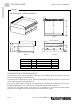
SPECIFICATI ONS SPECIFICATIONS HEAVY DUTY COUNTERLINE Figure 2 DIMENSIONS OF GRIDDLE MODELS 1.5" 24.0" 30.0" Top View Width (see table below) 31.5" 16.0" 15.1" 10.0" 11.0" 5.4" 2.0" 2.8" 29.
SPECIFICATIONS HEAVY DUTY COUNTERLINE SPECIFICATI ONS Figure 3 DIMENSIONS OF CHARBROILER MODELS 1.5" 21.5" 30.0" Top View Width (see table below) 31.5" 16.0" 15.1" 11.0" 10.0" 5.3" 2.8" 2.0" 29.4" Front View Side View Model Width Number and Size of Burners Total BTU HDC-24 & HDCL-24 HDC-36 & HDCL-36 HDC-48 & HDCL-48 24" 36" 48" 4 @ 20,000 6 @ 20,000 8 @ 20,000 80,000 120,000 160,000 CONSTRUCTION OF CHARBROILER MODELS The front, top-rail sides, and 5" riser are all stainless steel.
SPECIFICATI ONS SPECIFICATIONS HEAVY DUTY COUNTERLINE Figure 4 DIMENSIONS OF OPEN TOP MODELS 3.9" 2.0" 24.4" Top View Width (see table below) 2.8" 15.3" 11.0" 9.0" 6.3" Front View Side View Model Width Number and Size of Burners Total BTU HDO-12 HDO-24 & HDO-24SU HDO-36 & HDO-36SU 12.25" 24.5" 36.625" 2 @ 26,000 4 @ 26,000 6 @ 26,000 52,000 104,000 156,000 CONSTRUCTION OF OPEN TOP MODELS The front, top-rail sides, and 5" riser are all stainless steel.
INSTALLATION HEAVY DUTY COUNTERLINE I NSTALLATION NOTICE These installation procedures must be followed by qualified personnel or warranty will be void. Local codes regarding installation vary greatly from one area to another. The National Fire Protection Association, Inc. states in its NFPA 96 latest edition that local codes are the “authority having jurisdiction” when it comes to installation requirements for equipment. Therefore, installations should comply with all local codes.
INSTALLATION HEAVY DUTY COUNTERLINE Step 2a: Installation on Countertop Legs To install the appliance using countertop legs, do the following: 1. Locate the box of four legs shipped with the appliance (if countertop legs were ordered). INSTALLATION 2. Raise the appliance about 6" so that the legs can be screwed into the bottom near the corners. Lift the appliance only from the ends, never from the middle! Support the lifted appliance so that it will not fall while you are attaching the legs. 3.
INSTALLATION HEAVY DUTY COUNTERLINE Step 2b: Installation Directly on a Non-Combustible Countertop Surface The appliance may be installed directly onto a flat NON-COMBUSTIBLE surface, as follows: 1. Place the appliance in the position that it will be used. Lift the appliance only from the ends, never from the middle! 2. Connect the gas supply (see Step 4 on page 18), then return to this procedure. 4. Seal the appliance to the countertop using G.E.
INSTALLATION HEAVY DUTY COUNTERLINE Step 2c: Installation on Insulated Base The appliance may be installed onto a flat NON-COMBUSTIBLE (but heat sensitive) surface using the optional insulated base, as follows: 1. Attach the side pieces of the insulated base (items “A” in Figure 7 below) to the front piece (item “B”) using the four sheet metal screws provided. INSTALLATION 2. Position the insulated base on the surface where you want the appliance to be located. 3.
INSTALLATION HEAVY DUTY COUNTERLINE Step 2d: Installation on Floor Stand (24", 36", and 48" Models) The 24", 36", and 48" appliances may be installed on top of an optional floor stand (for 60" griddles, go to Step 2e on page 15). The floor stand is shipped in a separate crate and must be assembled, as follows: 1. Position the bottom-brace pieces on a flat surface, as shown in Figure 8 below.
INSTALLATION Figure 9 HEAVY DUTY COUNTERLINE
HEAVY DUTY COUNTERLINE INSTALLATION Step 2e: Installation on Floor Stand (60" Models) A 60" griddle may be installed on top of an optional floor stand (for 24", 36", and 48" griddles, go to Step 2d on page 13). The floor stand is shipped in a separate crate and must be assembled, as follows: 1. Position the bottom-brace pieces on a flat surface, as shown in Figure 10 below. There are four bottom-side braces (items “A”), and four front/rear bottom-braces (items “B”). 3.
INSTALLATION HEAVY DUTY COUNTERLINE Figure 11 J K P I K INSTALLATION I H H P J L L N O M 7. Check the partially assembled stand to make sure that the legs are straight and that all corners are square. Now tighten all bolts, but do not over tighten. 8. If legs with casters were ordered, lift the stand and screw the caster assemblies into the bottom of the legs. The two casters with wheel-locks go on the front corner legs.
INSTALLATION HEAVY DUTY COUNTERLINE Step 3: Attach Restraint for Appliances Mounted on Casters NOTICE ! WARNING To avoid accidental gas disconnection and potential explosion: If disconnection of this restraint is necessary to move the appliance for cleaning, etc., reconnect it when the appliance is moved to its originally installed position.
INSTALLATION HEAVY DUTY COUNTERLINE 2. Install eye-bolt (item “F”) to a frame member on the rear of the appliance. After checking carefully behind the frame member for adequate clearance, drill a 1/4" hole through the frame member. 3. Thread hex nut (item “G”) and slide the washer (item “H”) onto the eye-bolt. Insert the eye-bolt through the 1/4" drilled hole and secure with a washer (item “H”) and nylon lock nut (item “I”). 4.
INSTALLATION HEAVY DUTY COUNTERLINE 5. Connect the vent line from the pressure regulator to the outdoors in accordance with local codes or, in the absence of local codes, with the National Fuel Gas Code, ANSI Z223.1, Natural Gas Installation Code, CAN/CGA-B149.1, or the Propane Installation Code, CAN/CGA-B149.2, as applicable. 6. Connect the gas inlet of the pressure regulator to the building’s supply system. No segment of the gas supply connection to the appliance should be smaller than 3/4" NPT.
INSTALLATION HEAVY DUTY COUNTERLINE Step 7: Final Installation Steps for Griddle Models This step applies only to the installation of griddle models. New griddles should be carefully tempered and cared for in order to avoid possible damage. To break in a new griddle, do the following: 1. Wipe the griddle surface clean. INSTALLATION 2. Light all the griddle burners and turn them to 200°F for one hour. Then gradually bring each griddle up to frying temperature. 3.
OPERATION HEAVY DUTY COUNTERLINE O PERATION ! DANGER EXPLOSION HAZARD Purchaser of equipment must post in a prominent location, detailed instructions to be followed in the event the operator smells gas. Obtain the instructions from the local gas supplier. ! CAUTION ! CAUTION Top section pilots, when out, do not interrupt the flow of gas to the burners. Consequently, it is the responsibility of the operator to check the ignition of the burners, immediately after burner value has been turned “ON.
OPERATION HEAVY DUTY COUNTERLINE OPERATION OF GRIDDLE MODELS Each 12"-wide griddle section has a thermostatic-control knob on the front panel that directly controls the flow of gas, and so the heat. Turn the knob clockwise to increase the heat; turn it counterclockwise to reduce the heat. The griddle requires approximately 13 minutes of preheating to reach 350°F, and 45 minutes to even out. Do not waste gas or abuse equipment by leaving control knobs set at a high temperature if not required.
OPERATION HEAVY DUTY COUNTERLINE OPERATION OF CHARBROILER MODELS Each 6"-wide charbroiler section has a knob on the front panel that directly controls the flow of gas, and so the heat. Turn the knob counterclockwise to increase the heat; turn it clockwise to reduce the heat. To use the charbroiler, turn all the control knobs to the full “ON” position. (If any burners do not light, check the pilots and, if necessary, light the pilots as described later in this section.
OPERATION HEAVY DUTY COUNTERLINE OPERATION OF OPEN-TOP BURNER MODELS Each 12"-wide open-top burner section has two knobs on the front panel that directly control the flow of gas to the section’s two burners, and so control the heat. Turn a knob clockwise to increase the heat; turn it counterclockwise to reduce the heat. If any burners do not light, check the pilots and, if necessary, light the pilots as described later in this section. At the end of each day’s use, turn all knobs to the “OFF” position.
CLEANING HEAVY DUTY COUNTERLINE C LEANING Southbend equipment is constructed with the best quality materials and is designed to provide durable service when properly maintained. To expect the best performance, your equipment must be maintained in good condition and cleaned daily. Naturally, the frequency and extent of cleaning depends on the amount and degree of usage. Daily: • Remove, empty, and clean grease drawers of griddles and charbroilers. • Clean griddle drain chutes of griddles.
CLEANING HEAVY DUTY COUNTERLINE the metal. Rubbing cleanser, as gently as possible, in the direction of the polished lines will not mar the finish of the stainless steel. NEVER RUB WITH A CIRCULAR MOTION. Soil and burnt deposits which do not respond to the above procedure can usually be removed by rubbing the surface with SCOTCH-BRITE scouring pads or STAINLESS scouring pads. DO NOT USE ORDINARY STEEL WOOL, as any particles left on the surface will rust and further spoil the appearance of the finish.
ADJUSTMENTS HEAVY DUTY COUNTERLINE A DJUSTMENTS ! WARNING ADJUSTMENTS AND SERVICE WORK MAY BE PERFORMED ONLY BY A QUALIFIED TECHNICIAN WHO IS EXPERIENCED IN, AND KNOWLEDGEABLE WITH, THE OPERATION OF COMMERCIAL COOKING EQUIPMENT. HOWEVER, TO ASSURE YOUR CONFIDENCE, CONTACT YOUR AUTHORIZED SERVICE AGENCY FOR RELIABLE SERVICE, DEPENDABLE ADVICE OR OTHER ASSISTANCE, AND FOR GENUINE FACTORY PARTS.
ADJUSTMENTS HEAVY DUTY COUNTERLINE ADJUSTMENT OF PILOT FLAME (GRIDDLE MODELS) The pilots are adjusted at the factory. If later the pilots are over-adjusted to the point where the flame is leaving its port, or “blowing off,” the result is an unstable condition in which the pilot may extinguish. If necessary, adjust each burner’s pilot using the following procedure: 1.
ADJUSTMENTS HEAVY DUTY COUNTERLINE ADJUSTMENT OF BURNER FLAME The burners are adjusted at the factory. If necessary to adjust the burner flames, do the following for each burner: 1. Turn the burner’s control knob to the full ON position. 2. If the appliance was cold, wait 5 minutes before adjusting the burner flame. 3. Loosen the set screw that holds the sheet-metal air shutter in place. 4.
ADJUSTMENTS HEAVY DUTY COUNTERLINE ADJUSTMENT OF GRIDDLE THERMOSTATS Each burner’s control knob operates a snap-action thermostatic valve that was adjusted at the factory. If the griddle surface temperature is different from the thermostat dial setting, adjust the valve using the following procedure: 1. Turn all the control knobs to the 300°F. 2. Wait 30 minutes (or 1 hour if the griddle was cold). 3.
TROUBLESHOOTING HEAVY DUTY COUNTERLINE T ROUBLESHOOTING Consult the following table for troubleshooting guidance.
PARTS HEAVY DUTY COUNTERLINE P ARTS NOTICE INSTALLATION OF OTHER THAN GENUINE SOUTHBEND PARTS WILL VOID THE WARRANTY ON THIS EQUIPMENT. The serial plate is located inside of the control panel on the front of the appliance (see Figure 1 on page 3). Replacement parts may be ordered either through a Southbend Authorized Parts Distributor or a Southbend Authorized Service Agency. When ordering parts, please supply the Model Number, Serial Number, Part Number, and Description.
PARTS HEAVY DUTY COUNTERLINE Griddle Chassis Parts See drawing on following page.
PARTS HEAVY DUTY COUNTERLINE
PARTS HEAVY DUTY COUNTERLINE Griddle Gas System Parts See drawing on following page.
PARTS Additional Parts for Models with Electronic Ignition HEAVY DUTY COUNTERLINE
PARTS HEAVY DUTY COUNTERLINE Charbroiler Parts See drawing on following page.
PARTS HEAVY DUTY COUNTERLINE
PARTS HEAVY DUTY COUNTERLINE Open Top Parts See drawing on following page.
PARTS HEAVY DUTY COUNTERLINE
PARTS HEAVY DUTY COUNTERLINE Floor Stand Parts for 24", 36", and 48" Width Units See drawing on following page.
PARTS HEAVY DUTY COUNTERLINE Floor Stand Parts for 24", 36", and 48" Width Units See parts list on previous page. Model HDG-36 is shown.
PARTS HEAVY DUTY COUNTERLINE Floor Stand Parts for 60" Width Griddles See drawing on following page.
PARTS HEAVY DUTY COUNTERLINE
PARTS HEAVY DUTY COUNTERLINE Countertop Legs and Insulated-Base Parts Key 1 12" 1163561 1172857 2 N/A 1186662 Part Number for Unit Width* 24" 36" 48" 1163561 1163561 1163561 1172857 1172857 1172857 Part Number for HDG/HDC/HDCL 1182277 1182278 1182279 Part Number for HDO 1186663 1186664 N/A 60" 1163561 1172857 Qty Description 4 1 4" leg (single) 4" leg (set of 4) 1182280 1 Insulator Base Kit N/A 1 Insulator Base Kit PARTS OPERATOR’S MANUAL 1182845 REV 6 PAGE 45
HEAVY DUTY COUNTERLINE Notes: PAGE 46 OPERATOR’S MANUAL 1182845 REV 6
HEAVY DUTY COUNTERLINE Notes: OPERATOR’S MANUAL 1182845 REV 6 PAGE 47
HEAVY DUTY COUNTERLINE HEAVY DUTY COUNTERLINE A product with the Southbend name incorporates the best in durability and low maintenance. We all recognize, however, that replacement parts and occasional professional service may be necessary to extend the useful life of this unit. When service is needed, contact a Southbend Authorized Service Agency, or your dealer. To avoid confusion, always refer to the model number, serial number, and type of your unit.