MODEL SB1014F 16" X 60" LATHE 220V w/DRO Manual Insert PHONE: (360) 734-1540 • www.southbendlathe.com The Model SB1014F Lathe is the same machine as the Model SB1014 except for the following: • Added a 2-Axis Fagor Digital Readout (DRO). Except for the differences noted in this insert, all other content in the Model SB1014 Owner’s Manual applies to this machine.
Model SB1014F MANUAL INSERT Mfg. Since 4/11 0RGHO 6% ) 6RXWK %HQG [ /DWKH 9 ZLWK '52 2TQFWEV &KOGPUKQPU 9GKIJV NDU 9KFVJ UKFG VQ UKFG Z &GRVJ HTQPV VQ DCEM Z *GKIJV Z Z KP (QQVRTKPV .
Mfg. Since 4/11 MANUAL INSERT Model SB1014F .
Model SB1014F MANUAL INSERT Mfg. Since 4/11 6JTGCFKPI +PHQ 0WODGT QH .QPIKVWFKPCN (GGFU 4CPIG QH .
14" & 16" EVS TOOLROOM LATHES MODELS SB1012/SB1014/SB1037 - 220V MODELS SB1013/SB1015/SB1038 - 440V OWNER'S MANUAL Hundreds of Thousands of Lathes Sold With a Tradition of Q uality Since 1906! © March, 2010 by South Bend Lathe Co. For Machines Mfg.
Scope of Manual This manual helps the reader understand the machine, how to prepare it for operation, how to control it during operation, and how to keep it in good working condition. We assume the reader has a basic understanding of how to operate this type of machine, but that the reader is not familiar with the controls and adjustments of this specific model. As with all machinery of this nature, learning the nuances of operation is a process that happens through training and experience.
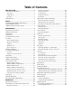
Table of Contents INTRODUCTION ....................................................3 About These Machines......................................... 3 Foreword ............................................................. 3 Capabilities ......................................................... 3 Features .............................................................. 3 Identification ........................................................ 4 SAFETY................................................................
Power Feed ......................................................... 44 Power Feed Controls .......................................... 45 Understanding Thread & Feed Rate Chart ......... 46 Positioning Gearbox Levers................................ 46 End Gear Setup ................................................. 47 Threading Controls ............................................ 48 Power Feed Lever .............................................. 48 Half Nut Lever ...........................................
For Machines Mfg. Since 7/09 INTRODUCTION INTRODUCTION EVS Toolroom Lathes About These Machines Foreword Features "The screw cutting engine lathe is the oldest and most important of machine tools and from it all other machine tools have been developed. It was the lathe that made possible the building of the steamboat, the locomotive, the electric motor, the automobile and all kinds of machinery used in industry.
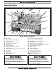
INTRODUCTION EVS Toolroom Lathes For Machines Mfg. Since 7/09 Identification I D C L M B E F A G J H N K O AB AA P Z X Y W V U T S R Q Figure 1. The 14" & 16" EVS Lathe. Headstock D1-6 Camlock MT#6 Spindle Control Panel Ball Bearing Style Steady Rest 4-Position Tool Holder Follow Rest Compound Slide Compound Slide Handwheel Work Lamp Universal Cutting Fluid Tube and Nozzle Cross Slide Tailstock Tailstock Handwheel Thread Dial O. Leadscrew Bearing Housing P. Cutting Fluid Pump/Tank Q.
For Machines Mfg. Since 7/09 SAFETY EVS Toolroom Lathes SAFETY Understanding Risks of Machinery Operating all machinery and machining equipment can be dangerous or relatively safe depending on how it is installed and maintained, and the operator's experience, common sense, risk awareness, working conditions, and use of personal protective equipment (safety glasses, respirators, etc.). The owner of this machinery or equipment is ultimately responsible for its safe use.
EVS Toolroom Lathes SAFETY For Machines Mfg. Since 7/09 5. Entanglement: Loose clothing, gloves, neckties, jewelry or long hair may get caught in moving parts, causing entanglement, amputation, crushing, or strangulation. Reduce this risk by removing/securing these items so they cannot contact moving parts. 11. Chuck Keys or Adjusting Tools: Tools used to adjust spindles, chucks, or any moving/ rotating parts will become dangerous projectiles if left in place when the machine is started.
For Machines Mfg. Since 7/09 SAFETY EVS Toolroom Lathes Additional Metal Lathe Safety 1. Clearing Chips. Metal chips can easily cut bare skin—even through a piece of cloth. Avoid clearing chips by hand or with a rag. Use a brush or vacuum to clear metal chips. 2. Chuck Key Safety. A chuck key left in the chuck can become a deadly projectile when the spindle is started. Always remove the chuck key after using it.
EVS Toolroom Lathes P R E PA R AT I O N For Machines Mfg. Since 7/09 PREPARATION Preparation Overview Things You'll Need The purpose of the preparation section is to help you prepare your machine for operation. The list below outlines the basic process to follow to prepare the lathe for operation. Specific steps for each of these points will be covered in detail later in this section. The typical preparation process is as follows: 1. Unpack the lathe and inventory the contents of the box/crate. 2.
For Machines Mfg. Since 7/09 P R E PA R AT I O N EVS Toolroom Lathes Inventory Main Inventory 1: (Figure 2) A. B. C. D. E. F. Steady Rest Assembly.................................... 1 12" Faceplate w/D1-6 Camlock Stud Set ...... 1 10" Four-Jaw Chuck w/Combo Jaws ............. 1 Four-Jaw Chuck Key ..................................... 1 Four-Jaw Chuck D1-6 Camlock Stud Set ..... 1 Follow Rest Assembly .................................... 1 Tool Box Inventory: (Figure 3) G. H. I. J. K. L. M. N. O. P. Q.
EVS Toolroom Lathes P R E PA R AT I O N For Machines Mfg. Since 7/09 Cleaning & Protecting The unpainted surfaces are coated at the factory with a heavy-duty rust preventative that prevents corrosion during shipment and storage. The benefit of this rust preventative is that it works very well. The downside is that it can be time-consuming to thoroughly remove. Be patient and do a careful job when cleaning and removing the rust preventative.
For Machines Mfg. Since 7/09 P R E PA R AT I O N EVS Toolroom Lathes Weight Load Location Refer to the Machine Specifications for the weight of your machine. Make sure that the surface upon which the machine is placed will bear the weight of the machine, additional equipment that may be installed on the machine, and the heaviest workpiece that will be used. Additionally, consider the weight of the operator and any dynamic loading that may occur when operating the machine.
EVS Toolroom Lathes P R E PA R AT I O N Lifting & Moving 4. This machine and its parts are heavy! Serious personal injury may occur if safe moving methods are not used. To reduce the risk of a lifting or dropping injury, ask others for help and use power equipment. To further balance the load, loosen the carriage lock bolt (see Figure 6), disengage the half nut lever, put the feed control lever in neutral, then use the carriage handwheel to move the carriage next to the tailstock.
For Machines Mfg. Since 7/09 6. P R E PA R AT I O N Attach the lifting straps to forklift forks or a hook and chain, as shown in Figures 8–9. Forklift Forks Lifting Straps EVS Toolroom Lathes Leveling & Mounting You must level your machine and either use the included foot pads and leveling hardware or bolt your lathe to the floor. Because mounting your lathe to the floor with permanent hardware is an optional step and floor materials may vary, floor mounting hardware is not included.
P R E PA R AT I O N EVS Toolroom Lathes To level the machine, use a precision level to make sure the bedways are level from side-toside and from front-to-back. — If using the included leveling pads (Figure 11), place them under the six leveling stud locations, then adjust the studs to level the lathe. For Machines Mfg. Since 7/09 Assembly With the exception of the handwheel handles, the lathe is shipped fully assembled.
For Machines Mfg. Since 7/09 P R E PA R AT I O N In addition to the gearboxes, we also recommend that you lubricate all other points on the machine at this time. This can be accomplished by following the maintenance schedule on Page 54. Note: If your lathe was shipped with oil in the gearboxes, do not change that oil until after the break-in period. Adding Cutting Fluid Add the cutting fluid of your choice now.
EVS Toolroom Lathes P R E PA R AT I O N Connecting Power Cord to Lathe For Machines Mfg. Since 7/09 To Power Source Wtt Rd B Bk L1 Electrocution or death will occur if you attempt this procedure with the power cord connected to the power source. The cord must be disconnected from power before performing this procedure. These instructions are for setups where the lathe will be connected to the power source with a power cord and plug, as opposed to a hardwire setup.
P R E PA R AT I O N For Machines Mfg. Since 7/09 Power Source Locking Disconnect Switch Conduit Test Run Machine After all preparation steps have been completed, the machine and its safety features must be tested to ensure correct operation. If you discover a problem with the operation of the machine or its safety components, shut the machine down, disconnect it from power, and do not operate it again until you have resolved the problem. Conduit Figure 16.
P R E PA R AT I O N EVS Toolroom Lathes 9. Stop Button For Machines Mfg. Since 7/09 Move the feed direction forward/reverse lever to the middle (neutral) position, as shown in Figure 20. Pump Switch FORWARD NEUTRAL REVERSE Figure 17. Control panel-test run. Turn the spindle speed dial (Figure 18) all the way counterclockwise (lowest speed) to avoid possibility of a high-speed start. 6. Spindle Speed Dial Low 20-400 RPM Figure 20. Feed direction forward/reverse lever in the neutral position. 10.
For Machines Mfg. Since 7/09 P R E PA R AT I O N 11. Move the spindle ON/OFF lever to the OFF (center) position, as shown in Figure 22. Spindle ON/OFF Lever Figure 22. Spindle ON/OFF lever-setup. 12. Connect the lathe to power source, then turn the main power switch (Figure 23) to the ON position. EVS Toolroom Lathes Note: This headstock has a pressurized oil system that is equipped with an oil pressure safety switch.
EVS Toolroom Lathes P R E PA R AT I O N 18. Move the spindle ON/OFF lever up to the OFF position, reset the stop button by twisting it clockwise until it pops out, then restart the spindle with the lever. 19. Push the foot brake. The lathe should come to a quick stop. — If the brake pedal has no effect on the lathe, push the stop button, and refer to V-Belts and Brake & Switch on Page 69 to make any required adjustments. 20. Remove the lathe headstock side cover.
P R E PA R AT I O N For Machines Mfg. Since 7/09 Spindle Break-In It is essential to closely follow the proper break-in procedures to ensure trouble-free performance. Complete this process once you have familiarized yourself with all instructions in this manual and completed the test run. 4. EVS Toolroom Lathes Move the feed direction forward/reverse lever (Figure 28) to the neutral position. FORWARD NEUTRAL REVERSE To complete the spindle break-in: 1.
P R E PA R AT I O N EVS Toolroom Lathes Disengage the half nut and the feed control levers shown in Figures 30–31. 5. Feed Control Lever Disengaged (Neutral Position) Half Nut Lever Disengaged (Up) Figure 30. Power fed and half nut levers disengaged. Cross Slide Neutral Carriage FEED CONTROL LEVER 7. After completing the previous step, stop the spindle and move the gearbox range lever to neutral, then move the spindle speed range lever to high. 8.
For Machines Mfg. Since 7/09 O P E R AT I O N EVS Toolroom Lathes OPERATION Operation Overview To complete a typical operation, the operator does the following: The purpose of this overview is to provide the novice machine operator with a basic understanding of how the machine is used during operation, so they can more easily understand the controls discussed later in this manual. 1.
O P E R AT I O N EVS Toolroom Lathes Description of Controls & Components Refer to the following figures and descriptions to become familiar with the basic controls of this machine. Main Power Switch A. Change Gear Chart: Displays the positions of the various gears for different threading or turning options. B. Spindle Speed Range Lever: Shifts the headstock into low or high range for spindle speeds between 20–400 RPM or 400–2500 RPM. C.
For Machines Mfg. Since 7/09 O P E R AT I O N H. Cutting Fluid Flow Control Lever: Controls the flow of cutting fluid from the nozzle. I. Compound Slide Handwheel: Moves the compound slide forward or backward. Includes an indirect-read graduated scale (distance represents actual tool movement— not amount of material removed). J. Carriage Lock Bolt: Secures the carriage in place for greater rigidity and accuracy when using the cross or compound slide for the machining operation. K.
O P E R AT I O N EVS Toolroom Lathes Tailstock Controls AB AA For Machines Mfg. Since 7/09 Foot Brake AD AC This lathe is equipped with a foot brake (Figure 38) to quickly stop the spindle. Pushing the foot brake while the spindle is ON cuts power to the motor and stops the spindle. Once stopped, the spindle lever MUST be returned to the neutral position before the spindle can be restarted. AE Spindle ON/OFF Lever AF AG Figure 37. Tailstock controls. AA.
For Machines Mfg. Since 7/09 O P E R AT I O N 3. Chuck & Faceplate Mounting This lathe is shipped with the 3-jaw chuck installed. This is a scroll-type chuck, meaning that all three jaws move in unison when adjusted. EVS Toolroom Lathes One at a time, use the chuck key to turn each of the camlocks counterclockwise until the cam line aligns with the cam release datum line, as shown in Figure 40. As you turn the camlocks, they will rise up slightly from the spindle body.
EVS Toolroom Lathes O P E R AT I O N Mounting Chuck or Faceplate The 4-jaw chuck is shipped with six camlock studs that must be installed before the chuck can be mounted, as explained in this procedure. If you have not yet installed the camlock studs, complete the instructions in "Installing and Adjusting Camlock Studs" on Page 29. To mount a chuck or faceplate: 1. DISCONNECT LATHE FROM POWER! 2.
For Machines Mfg. Since 7/09 O P E R AT I O N Installing and Adjusting Camlock Studs Camlock Stud Depth Mark is Even with Chuck or Faceplate Surface When fitting a chuck or faceplate with camlock studs, or when mounting a new chuck or faceplate, it may be necessary to install or adjust the camlock studs. Tool Needed Camlock Stud Locking Cap Screw Hole To install or adjust camlock studs onto a chuck or faceplate: 2. Lay the chuck or faceplate upside down on a protective, flat surface.
EVS Toolroom Lathes O P E R AT I O N For Machines Mfg. Since 7/09 Not Correct Correct Not Correct Figure 48. Correct camlock stud alignment. 3-Jaw Chuck Refer to Chuck & Faceplate Mounting instructions on Page 27 to mount the 3-jaw chuck to the spindle. The 3-jaw scroll-type chuck included with this lathe features hardened steel jaws that center the workpiece. When the operator opens or closes the jaws with the chuck key, the jaws move in unison.
For Machines Mfg. Since 7/09 O P E R AT I O N — If installed correctly, the jaws converge together at the center of the chuck. Changing Jaws Item Needed EVS Toolroom Lathes Qty Chuck Key ............................................................. 1 White Lithium Grease .......................... As Needed — If the jaws do not come together, remove them, then repeat this procedure until they do. To change the jaw: 1. DISCONNECT LATHE FROM POWER! Mounting Workpiece 2.
O P E R AT I O N EVS Toolroom Lathes 6. 4-Jaw Chuck Refer to Chuck & Faceplate Mounting instructions on Page 27 to mount the 4-jaw chuck to the spindle. The 4-jaw chuck features independently adjustable hardened steel jaws to hold noncylindrical or off-center workpieces. Each jaw can be removed from the chuck body and reversed for a wide range of work holding versatility. For Machines Mfg.
For Machines Mfg. Since 7/09 O P E R AT I O N Moving Along Bedway EVS Toolroom Lathes To install tooling in the tailstock: 1. Pull the tailstock lock lever backward (away from the spindle) to unlock the tailstock from the bedway. 1. With the tailstock locked in place, unlock the quill, then use the handwheel to extend it to the 1" mark on the quill. 2. Slide the tailstock to the desired position. 2. 3.
O P E R AT I O N EVS Toolroom Lathes For Machines Mfg. Since 7/09 Offsetting Aligning The tailstock can be offset from the spindle center line for turning tapers. The offset movement is controlled by set screws on both sides of the tailstock (see Figure 57), and the amount of movement is indicated by the offset scale on the back of the tailstock. The offset of your lathe was aligned with the spindle center line at the factory.
For Machines Mfg. Since 7/09 O P E R AT I O N Note: As long as this dead center remains in the chuck, the point of the center will remain true to the spindle center line. The point will have to be refinished whenever the center is removed and then returned to the chuck. 5. Install a center in the tailstock. 6. Attach a lathe dog to the piece of stock from Step 3, then mount it between the centers, as shown in Figure 60. 9. EVS Toolroom Lathes Use a caliper to measure both ends of the workpiece.
EVS Toolroom Lathes O P E R AT I O N Faceplate For Machines Mfg. Since 7/09 Non-Cylindrical Workpiece Refer to Chuck & Faceplate Mounting instructions on Page 27 to mount the faceplate to the spindle. The 12" faceplate included with your lathe offers a wide range of uses, including machining nonconcentric workpieces, straight turning between centers, off-center turning, and boring. Clamp The tools needed for mounting a workpiece will vary depending on the type of setup you have. Faceplate Figure 63.
For Machines Mfg. Since 7/09 O P E R AT I O N EVS Toolroom Lathes Centers Mounting Dead Center in Spindle Figure 65 shows the dead centers included with the lathe. In addition, an MT#6–MT#4 tapered spindle sleeve is included for mounting centers in the spindle. 1. DISCONNECT LATHE FROM POWER! 2. Thoroughly clean and dry the tapered mating surfaces of the spindle bore, tapered sleeve, and the center, making sure that no lint or oil remains on the tapers. 3.
O P E R AT I O N EVS Toolroom Lathes For Machines Mfg. Since 7/09 Removing Center from Spindle To mount a center in the tailstock: To remove the sleeve and center from the spindle, insert a piece of round bar stock or similar tool through the outboard end (on the left side of the headstock), then tap the sleeve loose. 1. DISCONNECT LATHE FROM POWER! 2.
O P E R AT I O N For Machines Mfg. Since 7/09 Steady Rest The steady rest supports long shafts and can be mounted anywhere along the length of the bed. EVS Toolroom Lathes 5. Close the steady rest so that the workpiece is inside the finger rollers, then tighten the lock knob. 6. Loosen the three wing bolts so the finger roller positions can be adjusted. To install and use the steady rest: 1. DISCONNECT LATHE FROM POWER! 7. 2.
O P E R AT I O N EVS Toolroom Lathes For Machines Mfg. Since 7/09 Compound Slide Four-Way Tool Post The compound slide handwheel has an indirectread graduated scale. This means that the distance shown on the scale represents the actual distance the tool moves, which will remove twice as much material from the diameter of the workpiece. The base of the compound slide has another graduated scale used for setting the tool to a specific angle.
For Machines Mfg. Since 7/09 O P E R AT I O N Tools Needed Aligning Cutting Tool with Tailstock Center For most operations, the cutting tool tip should be aligned with the spindle center line, as illustrated in Figure 73. Tool Post T-Wrench............................................... 1 Steel Shim ............................................. As Needed Cutting Tool........................................................... 1 Fine Ruler ..............................................................
O P E R AT I O N EVS Toolroom Lathes For Machines Mfg. Since 7/09 Adjustable Apron Stop Carriage Stop System Use the adjustable apron stop collar (shown in Figure 75) to set the location where the carriage will be disengaged by the feedrod friction clutch. When the adjustable apron stop contacts the stop collar during a carriage feeding operation, the clutch disengages the feedrod from the apron and the carriage movement stops.
O P E R AT I O N For Machines Mfg. Since 7/09 EVS Toolroom Lathes Manual Feed Spindle Speed You can manually move the cutting tool around the lathe for facing or turning operations using the handwheels shown in Figure 77 and described below. Using the correct spindle speed is important for safe and satisfactory results, as well as maximizing tool life.
O P E R AT I O N EVS Toolroom Lathes For Machines Mfg. Since 7/09 Setting Spindle Speed Make sure the spindle is turned OFF and it has come to a complete stop. 1. Use the chart in Figure 79 to determine the available spindle speed range closest to your calculated spindle speed. 2. 4. SPEEDS LEVER RPM Low 20-400 High 400-2500 Figure 79. Spindle speed range chart.
O P E R AT I O N For Machines Mfg. Since 7/09 3. Power Feed Controls The feed direction lever (Figure 81) controls direction of the carriage. The quick change feed direction knob (Figure 82) reverses the feed direction of the carriage while the lathe is running. FORWARD NEUTRAL EVS Toolroom Lathes Use the feed control lever on the front of the apron to engage power feed for either the carriage or the cross slide (see Figure 83). To engage the carriage, push the lever to the left and down.
O P E R AT I O N EVS Toolroom Lathes For Machines Mfg. Since 7/09 Understanding Thread & Feed Rate Chart Figure 84 shows the configurations of gearbox levers that are required to set the available feed rates. This same chart can also be found on the machine. METRIC THREADING INCH THREADING mm MODULAR OR DIAMETRAL TURNING FEED RATE (DIST./REVOLUTION) in. .2 LCT1Z .225 LCT2Z .25 LCT3Z 2.0 2.5 3.0 LCR1Y LCR3Y LCR6Y .3 .35 .4 LCT6Z LCT8Z LCS1Z 3.5 4.0 4.5 LCR8Y HCR3Z HCS2Y .45 .5 .
O P E R AT I O N For Machines Mfg. Since 7/09 EVS Toolroom Lathes End Gear Setup Alternate Position The gearbox drive gear on this lathe can be configured for the "normal position" or the "alternate position" (both described in following paragraphs), depending upon the type of operation to be performed. The lathe is shipped with the end gears in the normal position. Gears must be thoroughly cleaned and re-coated in grease before installing (refer to Page 61), and the backlash must be maintained at 0.
EVS Toolroom Lathes O P E R AT I O N For Machines Mfg. Since 7/09 Note: Take care not to misplace the key from the gear shaft. b. c. d. Clean away debris and grime from the gear and apply a light coat of machine oil. Swap the position of the gear, as shown in Figure 87, then align it with the key and insert it on the gear shaft. Re-install the flat washer and cap screw. Note: DO NOT overtighten the cap screw.
O P E R AT I O N For Machines Mfg. Since 7/09 EVS Toolroom Lathes Using Thread Dial and Chart TPI 2-54 Not Divisible By 4 Find the TPI (threads per inch) that you want to cut in the left column (see Figure 92), then reference the dial number to the right of it. The dial numbers indicate when to engage the half nut for a specific thread pitch. The thread dial chart can also be found on the front of the thread dial housing.
EVS Toolroom Lathes O P E R AT I O N Other Fractional TPI Use position 1 on the thread dial for cutting the TPI shown in Figure 97. 2¼,2¾, 3¼,3¾ Position 1 Only For Machines Mfg. Since 7/09 Chip Drawer The chip drawer shown in Figure 99 catches swarf and metal chips during the machining process. It easily slides open to provide access to swarf during cleanup. Also, the chip drawer contains a screen that allows runoff cutting fluid to drain back into the cutting fluid tank. Figure 97.
O P E R AT I O N For Machines Mfg. Since 7/09 EVS Toolroom Lathes Cutting Fluid System The cutting fluid system delivers cutting fluid through a positionable nozzle and is turned ON/ OFF by the control panel cutting fluid pump switch and the valve lever near the base of the nozzle hose (see Figure 100). BIOLOGICAL & POISON HAZARD! Use the correct personal protection equipment when handling cutting fluid. Follow federal, state, and fluid manufacturer requirements for proper disposal.
EVS Toolroom Lathes ACC ESSOR I ES ACCESSORIES Accessories This section includes the most common accessories available for your lathe, which may be available through your local South Bend Lathe Co. dealer. If you do not have a dealer in your area, please call us at (360) 734-1540 or email us at cs@southbendlathe.com. SB1268—Collet Attachment 5–C for SB1012, SB1013, SB1014, SB1015, SB1037 & SB1038 Lathes SB1269—Taper Attachment for SB1012, SB1013, SB1014, SB1015, SB1037 & SB1038 Lathes For Machines Mfg.
ACC ESSOR I ES For Machines Mfg. Since 7/09 SB1247—MT4 Bull Nose Center s #R -O STEEL HARDENED TO (2# Ò s 4APER ROLLER BALL BEARING CONSTRUCTION s 'REAT FOR TURNING PIPES 1.81" 6.73" EVS Toolroom Lathes SB1298—SBL Bench Lathe Shop Clock SB1299—SBL Toolroom Lathe Shop Clock SB1300—SBL Lathe with Man These fine traditional shop clocks are constructed with a metal antique-finished frame. They are easy to read from a distance and measure 14" in diameter. Pictures just don't do them justice.
EVS Toolroom Lathes MAINTENANCE For Machines Mfg. Since 7/09 MAINTENANCE Maintenance Schedule ! Always disconnect power to the machine before performing maintenance. Failure to do this may result in electrocution or accidental startup injury. Daily, During Operations s s s Daily, After Operations s s Each operator of this machine is responsible for ensuring proper care of the equipment. We strongly recommend all operators make a habit of following the daily maintenance procedures.
Day 1 3 4 5 6 7 8 9 10 11 12 13 14 15 16 17 18 19 20 21 22 23 24 25 26 27 28 29 30 31 See owner’s manual for more information regarding cutting fluid condition, replacement, disposal, and safety. 2 Change Headstock Oil Change Apron Oil Date of last annual service: Date of next annual service: Make copies of this page to use each month. Keep each chart as a maintenance record for your South Bend Lathe.
EVS Toolroom Lathes MAINTENANCE For Machines Mfg. Since 7/09 Monitoring Oil Temperature Lubrication Headstock Oil Type .. Mobil DTE Light or ISO 32 Equivalent Oil Amount .............................................. 7.5 Liters Check/Add Frequency .................................... Daily Change Frequency ...................................Annually The headstock lubrication system is the most important lubrication system on the machine.
For Machines Mfg. Since 7/09 MAINTENANCE Cleaning Pump System & Changing Oil 8. The headstock oil pump system must be cleaned and the oil changed after the break-in period and then annually (or every six months with hard service or extreme working conditions). EVS Toolroom Lathes After the tank is completely cleaned out, unthread the screen from the bottom of the pump suction pipe (see Figure 111), and remove the screen from the tank. To clean the oil pump system: 1. DISCONNECT LATHE FROM POWER! 2.
EVS Toolroom Lathes MAINTENANCE For Machines Mfg. Since 7/09 Gearbox Apron Oil Type ...... Mobil Vactra 2 or ISO 68 Equivalent Oil Amount ...................................................1 Liter Check/Add Frequency .................................... Daily Change Frequency ...................................Annually Oil Type ...... Mobil Vactra 2 or ISO 68 Equivalent Oil Amount ...................................................1 Liter Check/Add Frequency ....................................
For Machines Mfg. Since 7/09 MAINTENANCE EVS Toolroom Lathes Lead Screw & Feedrod Bearings Ways & Slides Oil Type ...... Mobil Vactra 2 or ISO 68 Equivalent Oil Amount ...................................................1 Liter Check/Add Frequency .................................... Daily The way pump shown in Figure 117 lubricates the saddle and cross slide way guides with the oil from the apron reservoir.
EVS Toolroom Lathes MAINTENANCE For Machines Mfg. Since 7/09 Ball Oilers Cleaning Electrical Box Filter Oil Type .. Mobil DTE Light or ISO 32 Equivalent Oil Amount ..........................................1 or 2 Drops Lubrication Frequency................................... Daily The door of the electrical box contains an air filter (Figure 120) to prevent dust from entering the box as the cooling fan pulls in cool air to reduce heat.
For Machines Mfg. Since 7/09 MAINTENANCE EVS Toolroom Lathes End Gearing Lubricating Grease Type ............................................... NLGI#2 Frequency ................ Annually or When Swapping 1. DISCONNECT LATHE FROM POWER! 2. Remove the headstock side cover and all the end gears shown in Figure 121. 3. Clean the end gears thoroughly with mineral spirits to remove all the old grease. Use a small brush if necessary to clean between the teeth. 4.
MAINTENANCE EVS Toolroom Lathes Cutting Fluid System The cutting fluid system consists of a fluid tank, pump, and flexible nozzle. The pump pulls fluid from the tank and sends it to the valve, which controls the flow of cutting fluid to the work area. When the valve is opened or closed, the fluid comes out of the nozzle and drains through the chip drawer and into the catch tray and then into the tank where it is picked up again by the pump. Figure 122 shows many of these components and their locations.
For Machines Mfg. Since 7/09 MAINTENANCE Changing Cutting Fluid When you replace the old cutting fluid, take the time to thoroughly clean out the chip drawer, catch tray, and chip tray. The entire job only takes about a 1⁄2 hour when you are prepared with the proper materials and tools. Make sure to dispose of all old fluid according to local regulations. Items Needed: Note: The electrical conduit was purposely left long, so the tank can be removed without disconnecting wires from the pump.
EVS Toolroom Lathes MAINTENANCE For Machines Mfg. Since 7/09 Machine Storage To prepare your machine for long-term storage (a year or more): If the machine is not properly prepared for storage, it may develop rust or corrosion. If decommissioning this machine, use the steps in this section to ensure that it remains in good condition for later use. 1. To prepare your machine for short-term storage (up to a year): 1. Pump out the old cutting fluid, and flush the lines and tank with warm, soapy water.
For Machines Mfg. Since 7/09 SERVICE SERVICE EVS Toolroom Lathes Backlash Adjustment Cross Slide Leadscrew Backlash is the amount of free play felt while switching rotation directions with the handwheel. This can be adjusted on the compound and cross slide leadscrews. Hex Wrench 3mm ................................................. 1 Hex Wrench 5mm ................................................ 1 Reducing backlash to less than 0.001" is impractical.
EVS Toolroom Lathes SERVICE Leadscrew End Play Adjustment Gib Adjustment After a long period of time, you may find that the leadscrew develops a small amount of end play. This lathe is designed so that leadscrew end play can be easily removed with adjustment. Tools Needed: For Machines Mfg. Since 7/09 Qty Open End Wrench 1" ............................................ 1 Hex Wrench 3mm ................................................. 1 Hex Wrench 5mm ................................................
For Machines Mfg. Since 7/09 SERVICE EVS Toolroom Lathes Half Nut Adjustment The half nut mechanism can be tightened if it becomes loose from wear. The pressure exerted by the half nut is controlled by a gib similar to the one in the saddle, which is on Page 66. The half nut gib is adjusted with two set screws. Tool Needed: Qty Hex Wrench 3mm ................................................. 1 Gib Screw To adjust the half nut: Figure 129. One of two rear saddle gib screws. 1.
SERVICE EVS Toolroom Lathes 4. Feedrod Clutch Adjustment Insert the hex wrench into the collar adjustment hole shown in Figure 135, and use the wrench to rotate the clutch collar. — If you need to increase the release point, rotate the clutch collar upward. This lathe has an adjustable feed clutch that helps protect the drivetrain from overload. The feed clutch release point is adjusted at the factory. However, it can be easily adjusted depending on operator requirements.
SERVICE For Machines Mfg. Since 7/09 EVS Toolroom Lathes V-Belts Brake & Switch V-belts stretch and wear with use, so check them on a monthly basis to ensure optimal power transmission. Replace all of the V-belts if any of them show signs of glazing, fraying, or cracking. Phillips Screwdriver #2 ........................................ 1 Open End Wrench 24mm...................................... 1 As the brake lining wears, the foot pedal develops more travel.
SERVICE EVS Toolroom Lathes 5. Remove pedal stop shown in Figure 139. 6. Move the brake band to the right one hole, and re-install the pedal stop, tightening it until it is just snug. For Machines Mfg. Since 7/09 Pedal Stop — If installing a new brake band, install the cap screw so there is one hole to the left for future brake adjustment. Move Brake Band to the Right to Adjust Brake Pedal Lever Cap Screw Move Pedal Stop Left or Right to Adjust Foot Pedal Height. Figure 139.
SERVICE For Machines Mfg. Since 7/09 Leadscrew Shear Pin Replacement 3. EVS Toolroom Lathes Rotate the shroud washer so the cutout lines up with the shear pin head, as shown in Figure 144. Shroud Washer Shear Pin Head 9mm 3mm 5.8mm 7mm 0.5mm 0.2mm Cutout 0.2mm NOTE: Shear Pin Material = S45C (SAE 1045) Figure 144. Shroud washer/pin alignment. Figure 142. Shear pin specifications. Tools Needed: Qty Phillips Screwdriver #2 ........................................
EVS Toolroom Lathes SERVICE Use the magnet to remove the shear pin head, then rotate the lathe spindle to line up the inner and outer bores, as shown in Figure 146. Next, use the magnet to remove the other half of the broken shear pin when it becomes visible. 7. Inner Bore Outer Bore For Machines Mfg. Since 7/09 Instead, take the time to carefully line up the two bores. You may file a slight chamfer on the end of the pin to make it easier to insert. 10.
SERVICE For Machines Mfg. Since 7/09 Gap Removal & Installation A portion of the lathe bed directly under the spindle, the gap insert (Figure 150), can be removed to create additional space for turning large diameter parts. The gap insert was installed, then ground flush with the bed at the factory to ensure precise fit and alignment. Therefore, if the gap insert is removed, it may be difficult to re-install with the same degree of flushness and accuracy as when installed at the factory. Gap Insert 2.
EVS Toolroom Lathes TROU B LESHOOTI NG For Machines Mfg. Since 7/09 TROUBLESHOOTING If you need replacement parts, or if you are unsure how to do any of the solutions given here, feel free to call us at (360) 734-1540. Symptom Machine does not start or a circuit breaker trips. Possible Cause Possible Solution 1. (First time operation only) Lathe is wired out of phase. 1. Correct out-of-phase wiring (refer to Page 17 for details). 2. Emergency stop push-button is engaged or at fault. 2.
For Machines Mfg. Since 7/09 Symptom TROU B LESHOOTI NG Possible Cause EVS Toolroom Lathes Possible Solution 1. Workpiece is unbalanced. 1. Re-install workpiece as centered with the spindle bore as possible. 2. Loose or damaged belt(s). 2. Tighten/replace the belt as necessary (Page 69). 3. V-belt pulleys are not properly aligned. 3. Align the V-belt pulleys. 4. Worn or broken gear present. 4. Inspect gears and replace if necessary. 5. Chuck or faceplate has become unbalanced. 5.
EVS Toolroom Lathes Symptom TROU B LESHOOTI NG Possible Cause For Machines Mfg. Since 7/09 Possible Solution Workpiece is tapered. 1. Headstock and tailstock are not properly aligned with each other. 1. Realign the tailstock to the headstock spindle bore centerline (Page 34). Chuck jaws will not move or do not move easily. 1. Chips lodged in the jaws or scroll plate. 1. Remove jaws, clean and lubricate scroll plate, then replace jaws. Carriage will not feed, or is hard to move. 1.
WAR R ANT Y WARRANTY & RETURNS Warranty This quality product is warranted by South Bend Lathe Company to the original buyer for one year from the date of purchase. This warranty does not apply to consumable parts, or defects due to any kind of misuse, abuse, negligence, accidents, repairs, alterations or lack of maintenance. We do not reimburse for third party repairs.
South Bend Lathe Co. P.O. Box 2027 Bellingham, WA 98227 PHONE: (360) 734-1540 (Administrative Offices) FAX: (360) 676-1075 (International) FAX: (360) 734-1639 (USA only) southbendlathe.
16" X 60" EVS TOOLROOM LATHES MODEL SB1014 - 220V MODEL SB1015 - 440V SPECIFICATIONS Hundreds of Thousands of Lathes Sold With a Tradition of Q uality Since 1906! © March, 2010 by South Bend Lathe Co. For Machines Mfg.
Machine Specifications P.O. Box 2027, Bellingham, WA 98227 U.S.A. PHONE: (360) 734-1540 • © South Bend Lathe Co. www.southbendlathe.com Model SB1014 16" x 60" EVS Toolroom Lathe Product Dimensions: Weight ........................................................................................................................................................................3300 lbs. Length/Width/Height ...........................................................................................................
Coolant Type .......................................................................................................................................................TEFC Induction Horsepower............................................................................................................................................................. 1⁄8 HP Voltage ......................................................................................................................................................
Dimensions Bed Width ................................................................................................................................................................ 101⁄4" Leadscrew TPI ...............................................................................................................................................................4 Leadscrew Length ...................................................................................................................................
Machine Specifications P.O. Box 2027, Bellingham, WA 98227 U.S.A. PHONE: (360) 734-1540 • © South Bend Lathe Co. www.southbendlathe.com Model SB1015 16" x 60" EVS Toolroom Lathe Product Dimensions: Weight ........................................................................................................................................................................3300 lbs. Length/Width/Height ...........................................................................................................
Coolant Type .......................................................................................................................................................TEFC Induction Horsepower............................................................................................................................................................. 1⁄8 HP Voltage ......................................................................................................................................................
Dimensions Bed Width ................................................................................................................................................................ 101⁄4" Leadscrew TPI ...............................................................................................................................................................4 Leadscrew Length ...................................................................................................................................
South Bend Lathe Co. P.O. Box 2027 Bellingham, WA 98227 PHONE: (360) 734-1540 (Administrative Offices) FAX: (360) 676-1075 (International) FAX: (360) 734-1639 (USA only) southbendlathe.
14" & 16" EVS TOOLROOM LATHES MODELS SB1012/SB1014/SB1037 - 220V MODELS SB1013/SB1015/SB1038 - 440V WIRING MANUAL Hundreds of Thousands of Lathes Sold With a Tradition of Q uality Since 1906! © November, 2009 by South Bend Lathe Co. For Machines Mfg.
Scope of Manual This manual assumes that the reader has a basic understanding of safe electrical practices and general wiring concepts, including how to safely make wire connections and avoid shorts. This manual is intended to be a reference source in the event that a repair or component replacement becomes necessary during the life of the machine.
For Machines Mfg. Since 8/09 ELECTRICAL EVS Toolroom Lathes ELECTRICAL Electrical Safety Instructions These pages are accurate at the time of printing. In the constant effort to improve, however, we may make changes to the electrical systems of future machines. Study this section carefully. If you see differences between your machine and what is shown in this section, call Technical Support at (360) 734-1540 for assistance BEFORE making any changes to the wiring on your machine. 1.
EVS Toolroom Lathes ELECTRICAL For Machines Mfg. Since 8/09 wiring overview Wiring Overview 7 Power Supply 6 Electrical Connection Page 13. Box, Pages 6 & 7. 220 VAC 3-PH 8 Spindle RPM Sensor, Page 14. Work Lamp, Page 14. B Chuck Guard Limit Switch, Page 14. A Brake Limit Switch, Page 14. @ 9 Door Limit Switch, Page 14. ? Oil Pressure Switch, > Page 10. Oil Pump Motor, Page 10. : Coolant Pump Motor, Page 11. = ; Control Panel, Page 12. Spindle Motor, Page 9.
For Machines Mfg. Since 8/09 EVS Toolroom Lathes ELECTRICAL visual index Component Location Index 6 Cooling Fan, 8 Work Lamp, Page 6. Page 14. 6 Electrical Box, Pages 6 & 7. 6 Main Power : Coolant Switch, Page 6. Pump Motor, Page 11. > Oil Pressure Sensor, Page 10. @ Brake Limit Switch, Page 14. ; Control Panel, Page 12. = Oil Pump Motor, Page 10. A Chuck Guard Limit Switch, Page 14. ? Door Limit Switch, Page 14. B Spindle RPM Sensor, Page 14. 8 Work Lamp, Page 14.
2 0 0 L13 24 L11 220 TRANSFORMER 9 9 6 7 6 7 L3 8 8 L4 19 20 12 13 14 63 64 U1 FOR 440V ONLY: SB1013 SB1015 SB1038 1 3 L2 5 L3 L1 4 NC AMP U1 2 T1 95 L2 5 L3 96 4 T2 V1 T2 97 98 W1 6 T3 NO L4 8 T4 7 THERMAL RELAY 6 T3 CONTACTOR Allen Bradley C09 400 3 L1 L2 A2 L3 L3 A1 6 4 L2 4 2 2 T1 1 L1 L1 2 MASTER POWER SWITCH L1 V1 U2 4 W2 W1 V2 L11 2 FOR 220V: RANGE 0.24A–0.4A, SET AT 0.35A FOR 440V: RANGE 0.24A–0.4A, SET AT 0.
To Spindle Motor, Page 9. U2 V2 W1 U1 V1 L13 L11 W = 1 ? 1 > 3 4 To Brake Limit Switch, Page 14. @ 8 9 To Spindle Switch, Page 13. 9 11 COM K B2 U N6H@6L6 W 10 V 11 ?3 ?4 ?5 ?# ?$ 7 9 G7 Varispeed L11 L13 To Spindle RPM Sensor, Page 14. L11 L13 8 To Work Lamp, Page 14. Limit Switch, Page 14. A To Chuck Guard Main Junction Block To Circuit Board, Page 6. B L 7 B1 A1 6 L3 12 14 18 23 5 To Oil Pressure Sensor, Page 10.
EVS Toolroom Lathes ELECTRICAL For Machines Mfg. Since 8/09 box photo Electrical Box Fig. 2. Electrical box.
For Machines Mfg. Since 8/09 EVS Toolroom Lathes ELECTRICAL he^cYaZ VcY ejbe bdidg 220V Spindle Motor < W6 W2 U5 U1 U6 V1 Yl V5 U2 W1 W5 V2 V6 W V Junction Box Bk U Bk Ground SPINDLE MOTOR (220V) 6 Figure. 3. Spindle motor location. To Electrical Box, Page 7. 440V Spindle Motor < W5 W2 W6 U1 U5 V1 Yl U6 U2 W1 V6 V2 V5 W V Bk U Junction Box Bk Ground SPINDLE MOTOR (440V) 6 Figure. 4. Spindle motor location. To Electrical Box, Page 7.
EVS Toolroom Lathes ELECTRICAL For Machines Mfg. Since 8/09 220V Oil Pump Motor & Pressure Sensor To Electrical Box, Page 7. > 6 Bk 2 Wt 11 X OIL PRESSURE SENSOR Oil Pressure Sensor and Pump U2 = U5 U2 U1 V1 V2 V5 W1 W2 W5 Ground 6 Oil Pump Motor U2 V2 W2 OIL PUMP MOTOR (220V) Figure. 5. Oil pump motor & pressure sensor location. To Electrical Box, Page 7. 440V Oil Pump Motor & Pressure Sensor To Electrical Box, Page 7.
For Machines Mfg. Since 8/09 ELECTRICAL EVS Toolroom Lathes 220V Coolant Pump Wiring 6 To Electrical Box, Page 7. : Coolant Pump 2 3 1 U1 V1 W1 5 W1 6 4 V1 Figure. 7. Coolant pump location. Ground Ground COOLANT PUMP MOTOR (220V) 440V Coolant Pump Wiring 6 To Electrical Box, Page 7. : Coolant Pump 2 3 1 U1 V1 W1 5 W1 6 4 V1 Figure. 8. Coolant pump location.
EVS Toolroom Lathes For Machines Mfg. Since 8/09 ELECTRICAL Control Panel Wiring control panel and coolant motor Control Panel Fig. 9. Control panel location. 6 To Main Junction Block, Page 7. To Main Junction Block, Page 7. To Circuit Board, Page 6. L L11 L13 COM 3 14 X To Circuit Board, Page 6. 4 2 12 X To Electrical Box, Page 7.
For Machines Mfg. Since 8/09 EVS Toolroom Lathes ELECTRICAL spindle rotation and power conntection Spindle Rotation Switch 6 8 Spindle Rotation Switch To Main Junction Block, Page 7. COM NC NO NO 9 7 6 NC COM 9 Spindle Rotation Switch, Figure 10. Fig. 10. Spindle rotation switch location. 220V Power Connection 7 Ground L1 Hot L3 L2 6 Hot Hot Inside Electrical Box, Page 7.
EVS Toolroom Lathes For Machines Mfg. Since 8/09 ELECTRICAL Additional Component Wiring Spindle RPM Sensor 8 Door Limit Switch Work Light additional compontnet Wt Fig. 11. RPM sensor and door limit switch location. Bk 2 0 Door Limit Switch, Figure 11. COMMON ? NO Brake Limit Switch Bk 0 Wt 1 X NC Spindle RPM Sensor, Figure 11. COM B K X L Fig. 12. Brake limit switch location. Chuck Guard Limit Switch, Figure 13. 3 NC 9 X A1 NO A 4 NC NO Brake Limit Switch, Figure 12.
WARRANTY & RETURNS Warranty This quality product is warranted by South Bend Lathe Company to the original buyer for one year from the date of purchase. This warranty does not apply to consumable parts, or defects due to any kind of misuse, abuse, negligence, accidents, repairs, alterations or lack of maintenance. We do not reimburse for third party repairs.
South Bend Lathe Co. P.O. Box 2027 Bellingham, WA 98227 PHONE: (360) 734-1540 (Administrative Offices) FAX: (360) 676-1075 (International) FAX: (360) 734-1639 (USA only) southbendlathe.
16" X 60" EVS TOOLROOM LATHES MODEL SB1014 - 220V MODEL SB1015 - 440V PARTS MANUAL Hundreds of Thousands of Lathes Sold With a Tradition of Q uality Since 1906! © November, 2009 by South Bend Lathe Co., Revised June, 2010 (TS) For Machines Mfg.
Scope of Manual The parts breakdowns in this manual are provided to facilitate the service and repair of this machine as follows: (1) By helping the mechanic understand how and where individual parts fit together; and (2) by establishing a numbering system from which available replacement parts can be ordered. Please note that not all parts shown are available for purchase and some individual parts may only be available in assemblies with other parts.
Table of Contents Headstock Casing....................................................................................................................................... 2 Headstock Controls..................................................................................................................................... 3 Headstock Upper Gearing.......................................................................................................................... 5 Headstock Transfer Gearing............
Model SB1014/SB1015 Parts For Machines Mfg. Since 8/09 PARTS Headstock Casing 1 2 3 4 10 5 7 6 11 9 8 9-1 12 13 REF PART # DESCRIPTION REF PART # DESCRIPTION 1 2 3 4 5 6 7 PSB10120001 PCAP29M PSB10120003 PSB10120004 PCAP50M PSB10120006 PCAP15M OIL FILL PLUG CAP SCREW M6-1 X 40 HEADSTOCK COVER COVER OIL SEAL M4 X 1700 CAP SCREW M5-.8 X 10 PIPE CLIP 5MM CAP SCREW M5-.8 X 20 8 9 9-1 10 11 12 13 PFH30M PSB10120009 PSB10120009-1 PSB10120010 PSB10120011 PSB10120012 PRIV001M FLAT HD SCR M5-.
PARTS For Machines Mfg.
Model SB1014/SB1015 Parts For Machines Mfg. Since 8/09 PARTS Headstock Controls Parts List REF PART # DESCRIPTION REF PART # DESCRIPTION 14 15 16 17 18 19 20 21 22 23 24 25 26 27 28 29 30 31 32 PSS30M PSB10120015 PSB10120016 PSTB001M PSB10120018 PORP014 PSB10120020 PORP021 PSB10120022 PR03M PSB10120024 PRP31M PSB10120026 PRP32M PSB10120028 PK01M PRP16M PSB10120031 PSB10120032 SET SCREW M10-1.5 X 10 THREADED PLUG M10-1.5 COMPRESSION SPRING M8 X 37 STEEL BALL 8.
99 34 96 98 96 78 80 79 100 81 97 96 95 77 94 93 75 34 92 76 73 66 91 74 90 72 57 89 88 71 70 87 34 65 86 69 67 66 86 65 64 63 82 83 62 61 60 68 59 60 58 57 56 55 PARTS 84 85 58 For Machines Mfg.
Model SB1014/SB1015 Parts For Machines Mfg. Since 8/09 PARTS Headstock Upper Gearing Parts List REF PART # DESCRIPTION REF PART # DESCRIPTION 34 55 56 57 58 59 60 61 62 63 64 65 66 67 68 69 70 71 72 73 74 75 76 77 PCAP01M PSB10120055 PORG050 PR38M P6206-OPEN PSB10120059 PK161M PSB10120061 PR76M PSB10120063 PSB10120064 PK27M PR15M PSB10120067 PSB10140068 PR11M P6205-OPEN PSB10120071 PSB10120072 PK62M P6206RS PORG085 PSB10120076 PSB10120077 CAP SCREW M6-1 X 16 INBOARD DRIVE SHAFT END CAP O-RING 54.
PARTS For Machines Mfg.
-8- 208 218 215 213 214 202 401 217 216 209 203 221 220 206 232 244 221 223 235 234 222 233 231 219 221 206 239 226 225 240 261 225 249 243 257 250 242 401 253 225 226 230 259 241 225 224 248 247 238 246 237 245 225 206 236 224 229 228 227 225 224 226 260 255 256 258 254 PARTS 211 206 211 212 210 206 401 207 201 203 204 205 206 251 252 401 Model SB1014/SB1015 Parts For Machines Mfg.
For Machines Mfg.
-10- 415 275 264 273 271 274 279 277 280 403 272 404 405 268 270 266 267 268 269 268 312 311 309 264 265 263 308 407 300 302 307 415 262 406 297 281 313 417 408 306 302 306408 301 408 303 304 312 314 290 287 288 289 283 285 288 286 315 409 322 324 310 412 321 413 319 320 414 316 317 411 318 414 323 PARTS 281 278 276 402 416 305 282 293 284 294 295 296 298 297 299 282 283 291 292 Model SB1014/SB1015 Parts For Machines Mfg.
For Machines Mfg.
538 -12- 608 516 517 606 549 539 522 501 609 526 540 521 525 502 502 537 514 610 519 601 541 522 518 505 503 504 542 514 534 603 506 527 547 523 510 513 511 512 546 606 607 605 529 530 548 528 524 603 514 515 602 601 532 531 604 PARTS 545 544 509 520 535 508 507 Model SB1014/SB1015 Parts For Machines Mfg.
For Machines Mfg.
-14- 568 611 569 613 550 573 514 559 613 567 612 582 522 573 574 561 581 575 614 555 580 563 577 579 578 562 556 576 608 554 553 566 565 PARTS 614 572 570 583 558 534 551 552 Model SB1014/SB1015 Parts For Machines Mfg.
For Machines Mfg. Since 8/09 PARTS Model SB1014/SB1015 Parts Apron - Rear View Parts List REF PART # DESCRIPTION REF PART # DESCRIPTION 514 522 534 550 551 552 553 554 555 556 558 559 561 562 563 565 566 567 568 PSTB001 PSB10120522 PORP012 PSB10120550 PSB10120551 PSB10120552 PSB10120553 PSB10120554 PSB10120555 PR11M PSB10120558 PRP88M PSB10120561 PSB10120562 PSB10120563 PSB10120289 PSB10120566 PSB10120567 PSB10120568 STEEL BALL 1/4 GEAR 18T O-RING 11.8 X 2.
Model SB1014/SB1015 Parts For Machines Mfg.
PARTS For Machines Mfg.
Model SB1014/SB1015 Parts For Machines Mfg.
For Machines Mfg.
Model SB1014/SB1015 Parts For Machines Mfg.
1327 1325 1324 1323 1311 1328 1326 1324 1321 1223A 1315 1310 1222 1231 1219 1238 1212 1215 1221 1309 1214 1217 1216 1213 1218 1230 1211 1210 1306 1318 1202 1206 1205 1318 1304 1303 1302 1207 1204 1305 1307 1227 1208 1229 1228 1314 1313 1209 1319 1220 1308 1318 1228 1237 1201 1301 1203 1316 1317 PARTS 1322 1320 1234 1235 1218 1232 1225 1312 1226 1236 1316 1317 For Machines Mfg.
Model SB1014/SB1015 Parts For Machines Mfg.
For Machines Mfg.
-24- 1536 1520 1534 1533 1531 1532 1533 1531 1531 1533 1502 1535 1524 1529 1523 1518 1512 1513 1526 1511 1510 1506 1527 1516 1514 1515 1517 1516 1528 1523 1525 1530 1530 1519 1519-2 1522 1519-1 1521 1506 1507 1509 1508 1519-3 1501 1502 1505 1504 1503 1503 1502 PARTS 1537 1538 1502 Model SB1014/SB1015 Parts For Machines Mfg.
For Machines Mfg. Since 8/09 PARTS Model SB1014/SB1015 Parts Motor Assembly Parts List REF PART # DESCRIPTION REF PART # DESCRIPTION 1501 1502 1503 1504 1505 1506 1507 1508 1509 1510 1511 1512 1513 1514 1515 1516 1517 1518 1519 1519-1 1519-2 PSB10121501 PN02M PW04M PSB10121504 PSB10121505 PCAP64M PSB10121507 PVB69 PSB10121509 PCAP01M PSB10121511 PSB10121512 PEC09M PSB10121514 PCAP45M PW01M PSB10121517 PSB10121518 PSB10141519 PSB10141519-1 PSB10141519-2 SIDE COVER MOUNTING PIN HEX NUT M10-1.
-26- 1616 1609 1608 1628 1626 1625 1605 1614 1624 1612 1603 1602 1610 1604 1611 1612 1606 1613 1603 1612 1614 1618 1639 1619 1632 1634 1640 1633 1634 1642 1636 1637 1638 1630 1654 1655 1643 1622 1614 1620 1621 1623 1644 1645 1603 1648 1649 1612 1646 1647 1652 1650 1653 1651 PARTS 1601 1612 1617 1627 1603 1631 1635 1629 Model SB1014/SB1015 Parts For Machines Mfg.
For Machines Mfg.
Model SB1014/SB1015 Parts For Machines Mfg.
For Machines Mfg. Since 8/09 PARTS Model SB1014/SB1015 Parts Headstock Oiling System Parts List REF PART # DESCRIPTION REF PART # DESCRIPTION 1701 1704 1705 1706 1707 1708 1709 1710 1711 1712 1713 1714 1715 1716 1717 1718 1719 1720 1721 1722 PSB10121701 PCAP50M PW02M PSB10121706 PSB10121707 PS34 PSB10121709 PN07M PSB10121711 PRP02M PSB10121713 PSB10121714 PSB10121715 PSB10121716 PCAP02M PN01M PCAP04M PSB10121720 PSB10121721 PSB10121722 ELBOW CONNECTOR CAP SCREW M5-.
Model SB1014/SB1015 Parts For Machines Mfg.
For Machines Mfg.
Model SB1014/SB1015 Parts Steady Rest 2001 2002 2012A For Machines Mfg.
PARTS For Machines Mfg.
Model SB1014/SB1015 Parts For Machines Mfg.
PARTS For Machines Mfg.
Model SB1014/SB1015 Parts For Machines Mfg.
PARTS For Machines Mfg.
South Bend Lathe Co. P.O. Box 2027 Bellingham, WA 98227 PHONE: (360) 734-1540 (Administrative Offices) FAX: (360) 676-1075 (International) FAX: (360) 734-1639 (USA only) southbendlathe.