IMPORTANT FOR FUTURE REFERENCE Please complete this information and retain this manual for the life of the equipment: Installation & Operations Manual Model #: _________________________ Serial #: _________________________ Date Purchased: _________________ Oven Range Model SE36 Manual 1189331 Rev 0 (02/07) $30..
This page intentionally left blank Page I Installation & Operations Manual 1189331 Rev 0 (02/07)
WARNING FOR YOUR SAFETY, DO NOT STORE OR USE GASOLINE OR OTHER FLAMMABLE VAPORS AND LIQUIDS IN THE VICINITY OF THIS OR ANY OTHER APPLIANCE. WARNING In case of fire, de-energize the Oven Range at its main disconnect switch/circuit breaker. Switching OFF the power to the Oven Range allows it to cool, making it easier to extinguish a fire. WARNING ONLY use a CO2 or other fire extinguisher suitable for grease, oil, and electrical equipment fires.
TABLE OF CONTENTS SECTION 1 DESCRIPTION .................................................................................................... 1 A. Oven Base ............................................................................................... 1 B. Range ....................................................................................................... 2 C. Specifications ........................................................................................... 7 SECTION 2 INSTALLATION ........
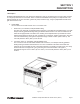
SECTION 1 DESCRIPTION I. Description Southbend Model SE36 electric oven ranges are rated heavy duty for commercial use. The oven range consists of a range top fastened to an oven base. There is a marine kit available which qualify it for shipboard use. The marine features are an oven door latch, grease tray latch, bolt-down legs , range top adjustable sea rails and a grab bar across the front. A. OVEN BASE the oven base can be either a deck oven or convection oven. 1.
Section 1 - Description B. RANGE The range can consist of up to 3 different components and the components can be configured in six ways. Troughs with drip chutes are located at the front and rear for draining into two wide drawer type receptacles 1. Range Components Descriptions a. Griddle for griddling. The griddle can be either 24”x24” or 24” x 36”. The griddles are controlled by thermostats.
Section 1 - Description b. 12”x24” Hot Plate for stock pot cooking (Not recommended for griddling). The hot plates are thermostatically controlled and have a temperature range of 250oF to 850oF (121oC to 454oC) and will preheat to 400oF (204oC) in 12 minutes Figure 1-3 Hot Plate c. Round Hot Plate for stock pot cooking. The twin hot plates have a 9” diameter and are controlled by 3heat (low, medium, high) switches.
Section 1 - Description 2. Range Top Configurations a. All purpose TOP SE36D/A-HHH. The all purpose top consists of three 12”x 24” hot plates. The all purpose top is not recommended for griddling Figure 1-5 All Purpose Plate b. Multi-Purpose Top SE36D/A-HHB The multi purpose top consists of two 12”x 24” hot plates and two 9” round hot plates. The multipurpose top is not recommended for gridling.
c. Griddling Top SE36D/A-TTT. the griddle top consists of one 36”x24” griddle plate. Figure 1-7 Griddle Top d. Round Hot Plate Top SE36D/A-BBB. The round hot plate top consists of six 9” hot plates.
Section 1 - Description e. Griddle/Round Hot Plate Top SE36D/A-TTB. The griddle/round hot plate top consists of one 24”x24” griddle and two 9” round hot plates. Figure 1-9 Griddle/Round Hot Plate f. Griddle 12”x24” Hot Plate Top SE36D/A-TTH. The griddle 12” x 24” hot plate top consists of one 24” x24” griddle and one 12”x24” hot plate.
Section 1 - Description C. Specifications OVEN RANGE MODELS SE36 Overall Dimensions Width Depth Height 36” (91.5cm) 38-3/4” (96.
Section 1 - Description NOTES Page 8 Installation & Operations Manual 1189331 Rev 0 (03/07)
SECTION 1 INSTALLATION A. Inspect for Shipping Damage All shipping containers should be examined for damage before and during unloading. This equipment was carefully inspected and packaged at the factory. the freight carrier has assumed responsibility for its safe transit and delivery. If equipment is received in damaged condition, either apparent or concealed, a claim must be made with the delivering carrier. 1.
Section 2 - INSTALLATION Figure 2-1 B. Inspect of Oven Range The oven range can be shipped assembled or the range top module and the oven can be packed in separate cartons. If the oven range is shipped assembled simply remove the metal banding straps and packing materials and move it to the permanent location. If the oven range is packed in two separate cartons and must be moved through a narrow passage follow the Pre-Installation instructions located on the outside of the carton.
Section 2 - INSTALLATION C. Assembling (Stacking) the Oven Module and Range Module 1. Move the range top module and the oven module to the area of their permanent location as directed in the previous Paragraph “B” or the Pre-installation Instructions on the outside of the shipping carton. 2. Remove the following (refer to Figure 2-1): • Two drip pans • Two side panels • Back cover • Front louvered panel located below control panel 3. Place range top module in position on oven module. 4.
Section 2 - INSTALLATION F. Testing the Installation 1. Turn all range and oven controls to the OFF position. 2. Turn main power disconnect switch to ON 3. Check range top components by turning on one control at a time starting at the left side of the control panel. Check that the component is starting to heat and then turn it off. 4. Check the oven controls. a. Deck oven - Set thermostat control at 300°F (149°C). turn both the upper and lower heating element switches to LOW.
Section 2 - INSTALLATION H.
Section 2 - INSTALLATION Figure 2-5 Page 14 Installation & Operations Manual 1189331 Rev 0 (03/07)
SECTION 2 OPERATION I. COMPONENT FUNCTION AND LOCATION A. OVEN BASE Module - either a convection oven or deck oven base. Convection Oven heating element located on side of oven cavity with the blower fan. Deck Oven has a heating element at both the top and bottom of the oven cavity. B. OVEN CONTROL PANEL - All Oven operating controls and indicators. C. RANGE TOP - Configured six different ways which consist of griddle, round hot plate, and/or 12” x 24” hot plate. D.
Section 3 - OPERATION II. Control Functions and Locations A. Convection Oven Control Panel Figure 3-2 Convection Control Panel 1. Temperature Thermostat Control - adjustable from 150°F to 450°F(65°C to 232°C). The thermostat is also provided with ON/OFF position. The oven will preheat to 450°F(232°C) in 15 minutes. 2. Heating Light - Amber light signals when oven is coming up to set temperature and heating element is energized. 3. Power Switch - turns ON or OFF. 4.
Section 3 - OPERATION B. Deck Oven Control Panel Figure 3-3 Deck Control Panel 1. Temperature Thermostat Control - adjustable from 200°F to 500°F(93°C to 287°C). The thermostat is also provided with ON/OFF position. The oven will preheat to 450°F(232°C) in 20 minutes. 2. Upper and Lower Heating Element Switches - are 3 position switches which adjust the heating elements at low, medium or high. The heating element switches also have an OFF position. 3.
Section 3 - OPERATION C. Range Top Controls Figure 3-4 Range Top with Griddle Control 1. Griddle is controller by a Temperature Thermostat Control (see Figure 3-4) adjustable from 150°F to 450°F(65°C to 232°C). The griddle will preheat to 400°F(204°C) in 12 minutes. Adjacent green light remains on while heating elements are energized and griddle is coming up to set temperature. Griddles have independent heat zones each with its own heating element and temperature control.
Section 3 - OPERATION III. Operation A. Convection Oven Operation 1. Set temperature control knob to the desired tenperature. 2. Push the oven power switch to the ON position. 3. Push the fan switch to the HIGH or LOW position. The LOW fan speed should be used for delicate products or products with loose toppings such as pepperoni on a pizza. Use HIGH fan speed for all other products that will not be affected by a fast air movement. 4. Allow oven to preheat to the set tmerpature.
Section 3 - OPERATION B. Deck Oven Operation 1. Set temperature control knob to the desired temperature. 2. Turn both Upper and Lower element switches to HIGH. 3. Allow oven to preheat to the set temperature. The amber signal light will remain on until the set temperature has been reached. 4. After oven is preheated set Upper and Lower element switches to desired setting (LOW, MEDIUM or HIGH).
Section 3 - OPERATION C. Griddle Operation IMPORTANT: Do not turn griddle on before seasoning procedure has been completed. IMPORTANT: If your griddle is new you must remove the rust preventative material before turning the griddle on. Refer to Section 2, Installation, Paragraph E. 1. Griddle Seasoning Procedure. a. Preheat the griddle to 300°F(149°C) and spread a light film of unsalted cooking oil or fat over the surface with a soft cloth. b.
Section 3 - OPERATION Daily Post Operations: a. Cleaning the Griddle Surface AA. Good cooking requires clean equipment. To provide evenly cooked and perfectly browned foods, keep the griddle surface free fo carbonized grease. Carbonized grease on the griddle surface hinders the transfer of heat from the griddle surface to the food.
Section 3 - OPERATION D. 12” x 24” Hot Plate Operation IMPORTANT: If your hot plate is new you must remove the rust preventative material before turning the griddle on. Refer to Section 2, Instalaltion, Paragraph E. 1. Turn the termperature controls to the desired temperature and allow 15 minutes of preheat timer before using the hot plate. the green signal light will remain on while the heating elements are eneergized and the hit plate is coming up to set temperature. 2.
Section 3 - OPERATION IV.
Section 3 - OPERATION DECK OVEN ROASTING TIME AND TEMPERATURE PRODUCT Beef Standing Rib. 3 Rib. 6-8 Pounds CONTROL SETTING INTERNAL MEAT TEMPERATURE MINUTES PER POUND 300°F(149°C) 20 25 30 13 15 17 25 20 - 30 12 - 16 Standing Rib. 7 Rib. 20-25 pounds 300°F(149°C) Rolled Rib. 7 Rib. 16-18 pounds Rump or Chuck. 8-23 pounds Round Rump. shank off. 50 pounds 250°F(121°C) 300°F(149°C) 300°F(149°C) Rare 140°F(60°C) Med. 160°F(71°C) Well 170°F(77°C) Rare 125°F(52°C) Med.
Section 3 - OPERATION CONVECTION OVEN BAKING TIME & TEMPERATURE This chart provides recommended temperature and time settings plus a number of racks per oven for specific food products. The times and temperature may, however, vary considerably due to weight of load, type of utensils and recipe. SIZE OF PAN NO.
Section 3 - OPERATION GRIDDLE TIME AND TEMPERATURE NOTE: All cooking times are approximate PRODUCT CONTROL TIME ADVANCE SETTING IN MINUTES PREPARATIONS Canadian Bacon 350°F(176°C) 3-4 Slice (not too far in advance as meat will darken) - Split edges to prevent curling. Hamburgers 350°F(176°C) 3-4 Prepare recipe - Form patties - Seperate with waxed paper - Refrigerate. Cheeseburgers 350°F(176°C) 3 -4 A hamburger patty plus melt a slice of cheese on top just before serving.
Section 3 - OPERATION NOTES Page 28 Installation & Operations Manual 1189331 Rev 0 (03/07)
SECTION 4 PARTS LIST Order parts by calling your authorized SOUTHBEND Parts Distributor, who has a complete inventory of parts for all SOUTHBEND equipment.
Section 4 - PARTS LIST Page 30 Installation & Operations Manual 1189331 Rev 0 (03/07)
Section 4 - PARTS LIST Installation & Operations Manual 1189331 Rev 0 (03/07) Page 31
Section 4 - PARTS LIST Page 32 Installation & Operations Manual 1189331 Rev 0 (03/07)
Section 4 - PARTS LIST Installation & Operations Manual 1189331 Rev 0 (03/07) Page 33
Section 4 - PARTS LIST Page 34 Installation & Operations Manual 1189331 Rev 0 (03/07)
Section 4 - PARTS LIST Installation & Operations Manual 1189331 Rev 0 (03/07) Page 35
Section 4 - PARTS LIST Page 36 Installation & Operations Manual 1189331 Rev 0 (03/07)
Section 4 - PARTS LIST Installation & Operations Manual 1189331 Rev 0 (03/07) Page 37
Section 4 - PARTS LIST NOTES Page 38 Installation & Operations Manual 1189331 Rev 0 (03/07)
SECTION 5 SCHEMATICS Installation & Operations Manual 1189331 Rev 0 (03/07) Page 39
Section 5 - SCHEMATICS Page 40 Installation & Operations Manual 1189331 Rev 0 (03/07)
Section 5 - SCHEMATICS Installation & Operations Manual 1189331 Rev 0 (03/07) Page 41
Section 5 - SCHEMATICS Page 42 Installation & Operations Manual 1189331 Rev 0 (03/07)
Section 5 - SCHEMATICS Installation & Operations Manual 1189331 Rev 0 (03/07) Page 43
Section 5 - SCHEMATICS Page 44 Installation & Operations Manual 1189331 Rev 0 (03/07)
Section 5 - SCHEMATICS Installation & Operations Manual 1189331 Rev 0 (03/07) Page 45
Section 5 - SCHEMATICS Page 46 Installation & Operations Manual 1189331 Rev 0 (03/07)
Section 5 - SCHEMATICS Installation & Operations Manual 1189331 Rev 0 (03/07) Page 47
Section 5 - SCHEMATICS Page 48 Installation & Operations Manual 1189331 Rev 0 (03/07)
Section 5 - SCHEMATICS Installation & Operations Manual 1189331 Rev 0 (03/07) Page 49
Section 5 - SCHEMATICS Page 50 Installation & Operations Manual 1189331 Rev 0 (03/07)
Section 5 - SCHEMATICS Installation & Operations Manual 1189331 Rev 0 (03/07) Page 51
Section 5 - SCHEMATICS Page 52 Installation & Operations Manual 1189331 Rev 0 (03/07)
Section 5 - SCHEMATICS Installation & Operations Manual 1189331 Rev 0 (03/07) Page 53
Section 5 - SCHEMATICS Page 54 Installation & Operations Manual 1189331 Rev 0 (03/07)
Section 5 - SCHEMATICS Installation & Operations Manual 1189331 Rev 0 (03/07) Page 55
Section 5 - SCHEMATICS Page 56 Installation & Operations Manual 1189331 Rev 0 (03/07)
Section 5 - SCHEMATICS Installation & Operations Manual 1189331 Rev 0 (03/07) Page 57
Section 5 - SCHEMATICS Page 58 Installation & Operations Manual 1189331 Rev 0 (03/07)
Section 5 - SCHEMATICS Installation & Operations Manual 1189331 Rev 0 (03/07) Page 59
Section 5 - SCHEMATICS Page 60 Installation & Operations Manual 1189331 Rev 0 (03/07)
Section 5 - SCHEMATICS Installation & Operations Manual 1189331 Rev 0 (03/07) Page 61
Section 5 - SCHEMATICS Page 62 Installation & Operations Manual 1189331 Rev 0 (03/07)
Section 5 - SCHEMATICS Installation & Operations Manual 1189331 Rev 0 (03/07) Page 63
Section 5 - SCHEMATICS Page 64 Installation & Operations Manual 1189331 Rev 0 (03/07)
Section 5 - SCHEMATICS Installation & Operations Manual 1189331 Rev 0 (03/07) Page 65
Section 5 - SCHEMATICS Page 66 Installation & Operations Manual 1189331 Rev 0 (03/07)
Section 5 - SCHEMATICS Installation & Operations Manual 1189331 Rev 0 (03/07) Page 67
Section 5 - SCHEMATICS Page 68 Installation & Operations Manual 1189331 Rev 0 (03/07)
Section 5 - SCHEMATICS Installation & Operations Manual 1189331 Rev 0 (03/07) Page 69
Section 5 - SCHEMATICS Page 70 Installation & Operations Manual 1189331 Rev 0 (03/07)
Section 5 - SCHEMATICS Installation & Operations Manual 1189331 Rev 0 (03/07) Page 71
Section 5 - SCHEMATICS Page 72 Installation & Operations Manual 1189331 Rev 0 (03/07)
Section 5 - SCHEMATICS Installation & Operations Manual 1189331 Rev 0 (03/07) Page 73
Section 5 - SCHEMATICS Page 74 Installation & Operations Manual 1189331 Rev 0 (03/07)
Section 5 - SCHEMATICS Installation & Operations Manual 1189331 Rev 0 (03/07) Page 75
Section 5 - SCHEMATICS Page 76 Installation & Operations Manual 1189331 Rev 0 (03/07)
Section 5 - SCHEMATICS Installation & Operations Manual 1189331 Rev 0 (03/07) Page 77
Section 5 - SCHEMATICS Page 78 Installation & Operations Manual 1189331 Rev 0 (03/07)
Section 5 - SCHEMATICS Installation & Operations Manual 1189331 Rev 0 (03/07) Page 79
Section 5 - SCHEMATICS Page 80 Installation & Operations Manual 1189331 Rev 0 (03/07)
Section 5 - SCHEMATICS Installation & Operations Manual 1189331 Rev 0 (03/07) Page 81
This page intentionally left blank Page 82 Installation & Operations Manual 1189331 Rev 0 (03/07)
This page intentionally left blank Installation & Operations Manual 1189331 Rev 0 (03/07) Page 83
Oven Range Model SE36 A product with the Southbend name incorporates the best in durability and low maintenance. We all recognize, however, that replacement parts and occasional professional service may be necessary to extend the useful life of this appliance. When service is needed, contact a Southbend Authorized Service Agency, or your dealer. To avoid confusion, always refer to the model number, serial number, and type of your appliance. Southbend 1100 Old Honeycutt Road, Fuquay-Varina, NC 27526 www.