OPERATOR’S MANUAL Counter Griddle Model Numbers SGS-24 SGS-36 SGS-48 SGS-60 MANUAL 1182629 REV 2 $9.
COUNTER GRIDDLE SAFETY PRECAUTIONS Before installing and operating this equipment, be sure everyone involved in its operation is fully trained and aware of precautions. Accidents and problems can be caused by failure to follow fundamental rules and precautions. The following symbols, found throughout this manual, alert you to potentially dangerous conditions to the operator, service personnel, or to the equipment. ! DANGER This symbol warns of immediate hazards that will result in severe injury or death.
TABLE OF CONTENTS COUNTER GRIDDLE Congratulations! You have purchased one of the finest pieces of commercial cooking equipment on the market. You will find that your new equipment, like all Southbend equipment, has been designed and manufactured to meet the toughest standards in the industry. Each piece of Southbend equipment is carefully engineered and designs are verified through laboratory tests and field installations.
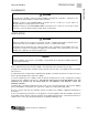
SPECIFICATIONS SPECIFICATIONS COUNTER GRIDDLE S PECIFICATIONS NOTICE Installation must comply with National Fuel Gas Code, ANSI Z223.1, Natural Gas Installation Code, CAN/CGA-B149.1, or the Propane Installation Code, CAN/CGA-B149.2, as applicable. Local codes regarding installation vary greatly from one area to another. The National Fire Protection Association, Inc.
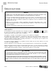
SPECIFICATIONS COUNTER GRIDDLE ! WARNING There must be adequate clearance between griddles and adjacent construction. Clearance in the front must also be provided for servicing and for operation. Minimum clearances from COMBUSTIBLE construction are 12" on sides, 8" on rear, and 4" on bottom (order the countertop legs or floor stand). Minimum clearances from NON-COMBUSTIBLE construction is 0" on sides, 2" on rear (the 2" deep stand-offs on the rear may be against a wall), and 0" on the bottom.
SPECIFICATIONS SPECIFICATIONS COUNTER GRIDDLE Figure 2 DIMENSIONS 2.24" 24.00" 29.08" Top View Width (see table below) 31.32" 16.00" 15.10" 9.96" 11.24" 5.34" 2.00" 2.78" 29.
INSTALLATION COUNTER GRIDDLE I NSTALLATION Installation must comply with National Fuel Gas Code, ANSI Z223.1, Natural Gas Installation Code, CAN/CGA-B149.1, or the Propane Installation Code, CAN/CGA-B149.2, as applicable. These installation procedures must be followed by qualified personnel or warranty will be void. Local codes regarding installation vary greatly from one area to another. The National Fire Protection Association, Inc.
INSTALLATION COUNTER GRIDDLE Step 2a: Installation on Countertop Legs To install the griddle using countertop legs, do the following: INSTALLATION 1. Locate the box of four legs shipped with the griddle (if countertop legs were ordered). 2. Raise the griddle about 6" so that the legs can be screwed into the bottom near the corners. Lift the griddle only from the ends, never from the middle! Support the lifted griddle so that it will not fall while you are attaching the legs. 3.
INSTALLATION COUNTER GRIDDLE Step 2b: Installation Directly on a Non-Combustible Countertop Surface The griddle may be installed directly onto a flat NON-COMBUSTIBLE surface, as follows: 1. Place the griddle in the position that it will be used. Lift the griddle only from the ends, never from the middle! 3. Check that the griddle is in the position you want it to be in. 4. Seal the griddle to the countertop using G.E. or Dow Corning RTV, or the equivalent (as shown in Figure 4 below).
INSTALLATION COUNTER GRIDDLE Step 2c: Installation on Insulated Base The griddle may be installed onto a flat NON-COMBUSTIBLE (but heat sensitive) surface using the optional insulated base, as follows: INSTALLATION 1. Attach the side pieces of the insulated base (items “A” in Figure 5 below) to the front piece (item “B”) using the four sheet metal screws provided. 2. Position the insulated base on the surface where you want the griddle to be located. 3. Position the griddle on top of the insulated base.
INSTALLATION COUNTER GRIDDLE Step 2d: Installation on Floor Stand (24", 36", and 48" Models) The 24", 36", and 48" griddles may be installed on top of an optional floor stand (for 60" griddles, go to Step 2e on page 13). The floor stand is shipped in a separate crate and must be assembled, as follows: 1. Position the bottom-brace pieces on a flat surface, as shown in Figure 6 below. There are two bottomside braces (items “A”), a bottom-front brace (item “B”), and an identical bottom-rear brace (item “B”).
INSTALLATION COUNTER GRIDDLE Figure 7 J K I INSTALLATION I H J L N O L M 7. Check the partially assembled stand to make sure that the legs are straight and that all corners are square. Now tighten all bolts, but do not over tighten. 8. If legs with casters were ordered, lift the stand and screw the caster assemblies into the bottom of the legs. The two casters with wheel-locks go on the front legs.
INSTALLATION COUNTER GRIDDLE Step 2e: Installation on Floor Stand (60" Models) A 60" griddle may be installed on top of an optional floor stand (for 24", 36", and 48" griddles, go to Step 2d on page 11). The floor stand is shipped in a separate crate and must be assembled, as follows: 1. Position the bottom-brace pieces on a flat surface, as shown in Figure 8 below. There are four bottomside braces (items “A”), and four front/rear bottom-braces (items “B”). 3.
INSTALLATION COUNTER GRIDDLE Figure 9 J K P INSTALLATION I K I H H P J L L N O M 7. Check the partially assembled stand to make sure that the legs are straight and that all corners are square. Now tighten all bolts, but do not over tighten. 8. If legs with casters were ordered, lift the stand and screw the caster assemblies into the bottom of the legs. The two casters with wheel-locks go on the front corner legs.
INSTALLATION COUNTER GRIDDLE Step 3: Attach Restraint for Griddles Mounted on Casters NOTICE Griddles mounted on a stand with casters or other movable surface must be equipped with a restraining means to prevent accidental stress on the flexible gas connection. 1. Secure the restraining-device bracket (item “B” in the following illustration) to a wall stud located as close as possible to the appliance connector inlet and outlet connections.
INSTALLATION COUNTER GRIDDLE Step 4: Connect Gas Supply INSTALLATION The serial plate is located interior side of the control panel (see Figure 1 on page 3). It indicates the type of gas the griddle is equipped to burn. All Southbend equipment is adjusted at the factory. Check type of gas on serial plate. This appliance should be connected ONLY to the type of gas for which it is equipped.
INSTALLATION COUNTER GRIDDLE Figure 11 INSTALLATION OPERATOR’S MANUAL 1182629 REV 2 PAGE 17
INSTALLATION COUNTER GRIDDLE Step 8: Check Griddle Temperature INSTALLATION Check (and, if necessary, adjust) the thermostatic valves that control the griddle’s surface temperature. Follow the procedure on page 24.
OPERATION COUNTER GRIDDLE O PERATION ! DANGER EXPLOSION HAZARD Purchaser of equipment must post in a prominent location, detailed instructions to be followed in the event the operator smells gas. Obtain the instructions from the local gas supplier. To eliminate gas build up which could result in an explosion, in the event of main burner ignition failure a five minute purge period must be observed prior to re-establishing ignition source.
OPERATION COUNTER GRIDDLE LIGHTING THE PILOTS If one or more of the burners does not ignite, check that the pilot(s) are lit. The controls for the pilots are located on the front of the griddle, behind the lower front panel door (see Figure 12 on page 20). To light the pilot(s), do the following: 1. Turn all griddle-thermostat controls to the “OFF” position. 2. Open the grease/control door at the bottom of the front of the griddle. OPERATION 3.
CLEANING COUNTER GRIDDLE C LEANING Southbend equipment is constructed with the best quality materials and is designed to provide durable service when properly maintained. To expect the best performance, your equipment must be maintained in good condition and cleaned daily. Naturally, the frequency and extent of cleaning depends on the amount and degree of usage. Daily: A. Remove, empty, and clean grease drawers. B. Clean griddle drain chutes. Monthly: A.
ADJUSTMENTS COUNTER GRIDDLE A DJUSTMENTS ! WARNING ADJUSTMENTS AND SERVICE WORK MAY BE PERFORMED ONLY BY A QUALIFIED TECHNICIAN WHO IS EXPERIENCED IN, AND KNOWLEDGEABLE WITH, THE OPERATION OF COMMERCIAL COOKING EQUIPMENT. HOWEVER, TO ASSURE YOUR CONFIDENCE, CONTACT YOUR AUTHORIZED SERVICE AGENCY FOR RELIABLE SERVICE, DEPENDABLE ADVICE OR OTHER ASSISTANCE, AND FOR GENUINE FACTORY PARTS.
ADJUSTMENTS COUNTER GRIDDLE ADJUSTMENTS OPERATOR’S MANUAL 1182629 REV 2 PAGE 23
ADJUSTMENTS COUNTER GRIDDLE THERMOSTAT ADJUSTMENT Each burner’s control knob operates a snap-action thermostatic valve that was adjusted at the factory. If the griddle surface temperature is different from the thermostat dial setting, adjust the valve using the following procedure: 1. Turn all the control knobs to the 300°F. 2. Wait 30 minutes (or 1 hour if the griddle was cold). 3.
ADJUSTMENTS COUNTER GRIDDLE CONVERSION FROM ONE TYPE OF GAS TO ANOTHER Each griddle is shipped equipped for use with either natural gas or LP gas (propane). To convert a griddle from one type of gas to another, do the following: 1. Remove the front panel by removing the knobs and screws on the front. 2. For each burner, replace the orifice with the type appropriate for the type of gas that will be used (see parts list on page 30).
TROUBLESHOOTING COUNTER GRIDDLE T ROUBLESHOOTING Problem Look for - Griddle will not heat up – Main gas supply to griddle is “OFF” – Pilot(s) not lit – Defective thermostat(s) – Clogged orifice or burner ports Burners produce excessive carbon deposits – Incorrect gas type or orifice size – Incorrect supply pressure – Incorrect burner air mixer adjustment – Burner orifice out of alignment with burner – Incorrect orifices Pilot produces excessive carbon deposits – Pilot gas not adjusted properly – In
PARTS COUNTER GRIDDLE P ARTS NOTICE INSTALLATION OF OTHER THAN GENUINE SOUTHBEND PARTS WILL VOID THE WARRANTY ON THIS EQUIPMENT. The serial plate is located inside of the control panel on the front of the griddle (see Figure 1 on page 3). Replacement parts may be ordered either through a Southbend Authorized Parts Distributor or a Southbend Authorized Service Agency. When ordering parts, please supply the Model Number, Serial Number, Part Number, and Description.
PARTS COUNTER GRIDDLE Chassis Parts See drawing on following page.
PARTS COUNTER GRIDDLE PARTS OPERATOR’S MANUAL 1182629 REV 2 PAGE 29
PARTS COUNTER GRIDDLE Gas System Parts See drawing on following page.
PARTS COUNTER GRIDDLE Gas System Parts See parts list on previous page. Model SGS-36 is shown.
PARTS COUNTER GRIDDLE Floor Stand Parts for 24", 36", and 48" Width Griddles See drawing on following page.
PARTS COUNTER GRIDDLE PARTS OPERATOR’S MANUAL 1182629 REV 2 PAGE 33
PARTS COUNTER GRIDDLE Floor Stand Parts for 60" Width Griddles See drawing on following page.
PARTS COUNTER GRIDDLE 15 16 PARTS OPERATOR’S MANUAL 1182629 REV 2 PAGE 35
PARTS COUNTER GRIDDLE Countertop Legs and Insulated-Base Parts 3 1 2 Key 1 2 3 ** ** 24" 1163561 1172857 1173884 1173883 1146304 1173888 Part Number for Griddle Width* 36" 48" 1163561 1163561 1172857 1172857 1173885 1173886 1173883 1173883 1146304 1146304 1173889 1173890 60" 1163561 1172857 1173887 1173883 1146304 1173891 Qty 4 1 1 2 4 1 Description 4" leg (single) 4" leg (set of 4) Insulator front piece Insulator side piece Screw #10 x 1/2 truss head Insulator base assembly (1 front, 2 sides, and
COUNTER GRIDDLE OPERATOR’S MANUAL 1182629 REV 2 PAGE 37
COUNTER GRIDDLE COUNTER GRIDDLE A product with the Southbend name incorporates the best in durability and low maintenance. We all recognize, however, that replacement parts and occasional professional service may be necessary to extend the useful life of this unit. When service is needed, contact a Southbend Authorized Service Agency, or your dealer. To avoid confusion, always refer to the model number, serial number, and type of your unit.