TURN-NADO® EVS LATHE w/DRO MODEL SB1042PF 21" X 60" MODEL SB1059F 18" X 40" MODEL SB1043PF 21" X 80" MODEL SB1060PF 18" X 60" MODEL SB1045PF 21" X 120" MODEL SB1061PF 18" X 80" OWNER'S MANUAL Hundreds of Thousands of Lathes Sold With a Tradition of Q uality Since 1906! © August, 2011 by South Bend Lathe Co. For Machines Mfg.
Scope of Manual This manual helps the reader understand the machine, how to prepare it for operation, how to control it during operation, and how to keep it in good working condition. We assume the reader has a basic understanding of how to operate this type of machine, but that the reader is not familiar with the controls and adjustments of this specific model. As with all machinery of this nature, learning the nuances of operation is a process that happens through training and experience.
Table of Contents INTRODUCTION ....................................................3 About This Machine ............................................. 3 Foreword ............................................................. 3 Capabilities ......................................................... 3 Features .............................................................. 3 General Identification .......................................... 4 Controls & Components.......................................
Headstock & Gearbox Threading Controls .......... 59 Apron Controls .................................................. 60 Thread Dial ....................................................... 61 Thread Dial Chart ............................................. 61 Chip Drawer ....................................................... 63 Coolant System .................................................. 63 Rod Support........................................................ 64 ACCESSORIES ............................
For Machines Mfg. Since 3/11 INTRODUCTION Turn-Nado® EVS Lathes About This Machine Foreword Features "The screw cutting engine lathe is the oldest and most important of machine tools and from it all other machine tools have been developed. It was the lathe that made possible the building of the steamboat, the locomotive, the electric motor, the automobile and all kinds of machinery used in industry. Without the lathe our great industrial progress of the last century would have been impossible.
INTRODUCTION Turn-Nado® EVS Lathes For Machines Mfg. Since 3/11 General Identification G E D H C I J K L F B A M N O U T S R Q P Figure 1. General identification (Model SB1043PF shown). A. B. C. D. E. F. G. H. I. J. K.
For Machines Mfg. Since 3/11 INTRODUCTION Controls & Components Turn-Nado® EVS Lathes Headstock Controls D Refer to Figures 2–9 and the following descriptions to become familiar with the features and basic controls of this lathe. This knowledge will be necessary to properly set up the lathe for the test run and spindle break-in. E C B To reduce the risk of serious injury when using this machine, read and understand this entire manual before beginning any lathe operations.
INTRODUCTION Turn-Nado® EVS Lathes Control Panel G H For Machines Mfg. Since 3/11 Carriage P I L Q O T N J S M K U R V W Figure 4. Control panel. G. Tachometer Display: Displays the current spindle speed in RPM's. H. Y Spindle Speed Dial: Electronically varies the spindle speed within the selected spindle speed range. X Figure 5. Carriage controls. I. Power Light: Illuminates when lathe controls are receiving power. M. Carriage Handwheel: Moves the carriage along the bed.
For Machines Mfg. Since 3/11 U. INTRODUCTION Thread Dial and Chart: Dial indicates when to engage the half nut during threading operations. Chart indicates on which thread dial reading to engage the half nut for specific inch thread pitches. Turn-Nado® EVS Lathes Tailstock AB AC AD AA V. Spindle Lever: Starts, stops and reverses direction of spindle rotation. W. Feed ON/OFF Lever: Engages/disengages power feed. X. Y.
Turn-Nado® EVS Lathes INTRODUCTION For Machines Mfg. Since 3/11 Safety Foot Brake AG AH This lathe is equipped with a foot brake (see Figure 9) to quickly stop the spindle instead of allowing it to coast to a stop on its own. Pressing the foot brake while the spindle is ON also cuts power to the motor. After the foot brake is used, the spindle lever must be returned to the OFF (middle) position to reset the spindle switches before spindle rotation can be re-started. AJ AI Spindle Lever Figure 8.
For Machines Mfg. Since 3/11 INTRODUCTION Turn-Nado® EVS Lathes Product Specifications P.O. Box 2027, Bellingham, WA 98227 U.S.A. 0(/.% s © South Bend Lathe Co. www.southbendlathe.com MODEL SB1042PF, SB1043PF, SB1045PF 21" EVS TOOLROOM LATHE w/DRO Model Number SB1042PF SB1043PF SB1045PF 5830 lbs. 6600 lbs. 8140 lbs.
Turn-Nado® EVS Lathes Model Number INTRODUCTION SB1042PF For Machines Mfg. Since 3/11 SB1043PF SB1045PF Main Motor Type TEFC Induction Horsepower 12.5 HP Voltage 440V Phase 3-Phase Amps 18A Speed 0–3000 RPM Cycle 60 Hz Power Transfer V-Belt & Gear Bearings Shielded & Permanently Sealed Coolant Motor Type TEFC Induction Horsepower 1 Voltage 440V Phase ⁄8 HP 3-Phase Amps 0.
For Machines Mfg. Since 3/11 Model Number INTRODUCTION SB1042PF SB1043PF Turn-Nado® EVS Lathes SB1045PF Headstock Information Spindle Bore 3.15 in. Spindle Taper MT#7 Number of Spindle Speeds Variable Range of Spindle Speeds 18–1800 RPM Spindle Type D1-8 Camlock Spindle Bearings Tapered Roller Tailstock Information Tailstock Quill Travel 6.5 in. Tailstock Taper MT#5 Tailstock Barrel Diameter 3 in. Threading Information Number of Longitudinal Feeds 15 Range of Longitudinal Feeds 0.
Turn-Nado® EVS Lathes Model Number INTRODUCTION SB1042PF For Machines Mfg.
For Machines Mfg. Since 3/11 INTRODUCTION Turn-Nado® EVS Lathes Product Specifications P.O. Box 2027, Bellingham, WA 98227 U.S.A. 0(/.% s © South Bend Lathe Co. www.southbendlathe.com MODEL SB1059F, SB1060PF, SB1061PF 18" EVS TOOLROOM LATHE w/DRO Model Number SB1059F SB1060PF SB1061PF 4400 lbs. 5170 lbs. 5940 lbs.
Turn-Nado® EVS Lathes Model Number INTRODUCTION SB1059F For Machines Mfg. Since 3/11 SB1060PF SB1061PF Main Motor Type Horsepower TEFC Induction 10 HP Voltage 440V Phase Amps 12.5 HP 3-Phase 16A 18A Speed 0–3000 RPM Cycle 60 Hz Power Transfer V-Belt & Gear Bearings Shielded & Permanently Sealed Coolant Motor Type TEFC Induction Horsepower 1 Voltage 440V ⁄8 HP Phase 3-Phase Amps 0.
For Machines Mfg. Since 3/11 Model Number INTRODUCTION SB1059F SB1060PF Turn-Nado® EVS Lathes SB1061PF Headstock Information Spindle Bore 3.15 in. Spindle Taper MT#7 Number of Spindle Speeds Variable Range of Spindle Speeds 18–1800 RPM Spindle Type D1-8 Camlock Spindle Bearings Tapered Roller Tailstock Information Tailstock Quill Travel 6.5 in. Tailstock Taper MT#5 Tailstock Barrel Diameter 3 in. Threading Information Number of Longitudinal Feeds 15 Range of Longitudinal Feeds 0.
Turn-Nado® EVS Lathes Model Number INTRODUCTION SB1059F For Machines Mfg.
For Machines Mfg. Since 3/11 SAFETY Turn-Nado® EVS Lathes Understanding Risks of Machinery Operating all machinery and machining equipment can be dangerous or relatively safe depending on how it is installed and maintained, and the operator's experience, common sense, risk awareness, working conditions, and use of personal protective equipment (safety glasses, respirators, etc.). The owner of this machinery or equipment is ultimately responsible for its safe use.
Turn-Nado® EVS Lathes SAFETY For Machines Mfg. Since 3/11 Entanglement: Loose clothing, gloves, neckties, jewelry or long hair may get caught in moving parts, causing entanglement, amputation, crushing, or strangulation. Reduce this risk by removing/securing these items so they cannot contact moving parts. Chuck Keys or Adjusting Tools: Tools used to adjust spindles, chucks, or any moving/ rotating parts will become dangerous projectiles if left in place when the machine is started.
For Machines Mfg. Since 3/11 SAFETY Turn-Nado® EVS Lathes Additional Metal Lathe Safety Speed Rates. Operating the lathe at the wrong speed can cause nearby parts to break or the workpiece to come loose, which will result in dangerous projectiles that could cause severe impact injuries. Large or non-concentric workpieces must be turned at slow speeds. Always use the appropriate feed and speed rates. Chuck Key Safety.
Turn-Nado® EVS Lathes SAFETY For Machines Mfg. Since 3/11 Additional Chuck Safety Entanglement. Entanglement with a rotating chuck can lead to death, amputation, broken bones, or other serious injury. Never attempt to slow or stop the lathe chuck by hand, and always roll up long sleeves, tie back long hair, and remove any jewelry or loose apparel BEFORE operating. Chuck Speed Rating.
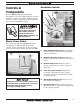
For Machines Mfg. Since 3/11 P R E PA R AT I O N Turn-Nado® EVS Lathes PREPARATION Preparation Overview Things You'll Need The purpose of the preparation section is to help you prepare your machine for operation. The list below outlines this basic process. Specific steps for each of these points will be covered in detail later in this section. The typical preparation process is as follows: 1. Unpack the lathe and inventory the contents of the box/crate. 2. Clean the lathe and its components. 3.
Turn-Nado® EVS Lathes P R E PA R AT I O N For Machines Mfg. Since 3/11 Power Supply Requirements The full-load current is not the maximum amount of amps that the machine will draw. If the machine is overloaded, it will draw additional amps beyond the full-load rating. Availability If the machine is overloaded for a sufficient length of time, damage, overheating, or fire may result—especially if connected to an undersized circuit.
For Machines Mfg. Since 3/11 P R E PA R AT I O N Turn-Nado® EVS Lathes Grounding Requirements 440V Operation This machine must be grounded! In the event of certain types of malfunctions or breakdowns, grounding provides a path of least resistance for electric current in order to reduce the risk of electric shock. As specified in the Circuit Requirements section on the previous page, these machines must be hardwired to the power source, using a locking switch (see Figure 10).
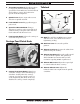
Turn-Nado® EVS Lathes P R E PA R AT I O N Unpacking This item was carefully packaged to prevent damage during transport. If you discover any damage, please immediately call Customer Service at (360) 734-1540 for advice. You may need to file a freight claim, so save the containers and all packing materials for possible inspection by the carrier or its agent. For Machines Mfg. Since 3/11 B A C D G E Inventory Main Inventory 1 (Figure 11) Steady Rest Assembly (Installed) .................
For Machines Mfg. Since 3/11 P R E PA R AT I O N Turn-Nado® EVS Lathes Cleaning & Protecting The unpainted surfaces are coated at the factory with a heavy-duty rust preventative that prevents corrosion during shipment and storage. The benefit of this rust preventative is that it works very well. The downside is that it can be time-consuming to thoroughly remove. Be patient and do a careful job when cleaning and removing the rust preventative.
P R E PA R AT I O N Turn-Nado® EVS Lathes For Machines Mfg. Since 3/11 Weight Load Location Physical Environment The physical Environment environment where your machine Physical is operated is important for safe operation and Electrical Installation longevity of parts. For best results, operate this machine in a dry environment that is free from Lighting excessive moisture, hazardous or flammable Weight Load chemicals, airborne abrasives, or extreme Space conditions.
For Machines Mfg. Since 3/11 P R E PA R AT I O N Lifting & Moving 5. Turn-Nado® EVS Lathes Position hardwood blocking under each end of the bed as shown in Figure 14. This will keep the lifting straps away from the leadscrew, feed rod, and spindle rod to prevent bending them during lifting. Note: Fasten a center support between the hardwood blocking to that they will stay spread apart and in place when lifting (see the example in Figure 15).
Turn-Nado® EVS Lathes P R E PA R AT I O N Attach the lifting straps to the power lifting equipment (see Figure 16 for an example). 6. Use Blocks as Necessary to Space Straps Away from Control Rod, Feed Rod, and Leadscrew to Prevent Bending when the Lathe is Lifted Power Lifting Equipment Lifting Straps For Machines Mfg. Since 3/11 Leveling & Mounting You must level your machine and either use the included foot pads and leveling hardware or bolt and shim your lathe to the floor.
P R E PA R AT I O N For Machines Mfg. Since 3/11 To level the machine, use a precision level to make sure the bedways are level from side-toside and from front-to-back. — If using the included leveling pads (see Figure 18), place them under the six leveling jack bolt locations, then adjust the bolts to level the lathe. Turn-Nado® EVS Lathes Assembly With the exception of the handwheel handles, the lathe is shipped fully assembled.
Turn-Nado® EVS Lathes P R E PA R AT I O N Lubricating Lathe GEARBOXES MUST BE FILLED WITH OIL! LATHE MAY NOT HAVE OIL INCLUDED! Refer to the Lubrication Section in this Manual for Recommended Oil Type. The headstock, quick-change gearbox, and apron oil reservoirs must have the proper amount of oil in them before the lathe can be operated for the first time. Damage caused to the bearings and gears from running the lathe without oil in the reservoirs will not be covered under warranty.
For Machines Mfg. Since 3/11 P R E PA R AT I O N Turn-Nado® EVS Lathes 3. Connect the incoming hot wires to the upper master power switch terminals and the ground wire to the ground terminal, as illustrated in Figure 23. Electrocution could occur if you attempt this procedure with the power wires connected to the power source. The incoming power wires must be disconnected from power before performing this procedure. Ground Connecting Power 1.
Turn-Nado® EVS Lathes P R E PA R AT I O N Test Run After all preparation steps have been completed, the machine and its safety features must be tested to ensure correct operation. If you discover a problem with the operation of the machine or its safety components, shut the machine down, disconnect it from power, and do not operate it further until you have resolved the problem.
P R E PA R AT I O N For Machines Mfg. Since 3/11 7. Move the spindle speed range lever to the low speed range 1 (18-55 RPM), as shown in Figure 26. Note: You may need to rock the spindle backand-forth by hand to mesh the gears. Turn-Nado® EVS Lathes Half Nut Lever Feed ON/OFF Lever Feed ON/OFF Lever Figure 26. Spindle speed range lever. 8. Move the gearbox range lever on the headstock to the neutral (middle) position to disable power feed, as shown in Figure 27.
Turn-Nado® EVS Lathes P R E PA R AT I O N 13. Move the spindle lever down to start the spindle rotating counterclockwise (down toward the front of the lathe). — If the spindle rotates in the opposite direction (clockwise), the power supply phase polarity may be incorrect. Refer to Correcting Phase Polarity on Page 92 to resolve this. 14. Observe the lathe and listen for any abnormal noises or vibration. The lathe should run smoothly. 15.
For Machines Mfg. Since 3/11 P R E PA R AT I O N Spindle Break-In Before subjecting the lathe to full loads, it is essential to complete the spindle break-in process as described below. This will ensure the best results and maximum life of the precision components inside the lathe. The break-in procedure must be performed in succession with the Test Run procedure described in this manual, because many of the test run steps prepare the lathe controls for the break-in process.
Turn-Nado® EVS Lathes O P E R AT I O N For Machines Mfg. Since 3/11 OPERATION Operation Overview To complete a typical operation, the operator does the following: The purpose of this overview is to provide the novice machine operator with a basic understanding of how the machine is used during operation, so they can more easily understand the controls discussed later in this manual. 1.
For Machines Mfg. Since 3/11 Turn-Nado® EVS Lathes O P E R AT I O N Chuck & Faceplate Mounting Installation & Removal Devices This lathe is equipped with a D1-type spindle nose. This type of spindle uses camlocks that are adjusted with a chuck key to securely mount a chuck or faceplate with repeatable precision and ease. Because chucks are heavy and often awkward to hold, some kind of lifting, support, or protective device should be used during installation or removal.
Turn-Nado® EVS Lathes O P E R AT I O N Chuck Installation To ensure accurate work, it is extremely important to make sure the spindle nose and chuck mating surfaces/tapers are clean. Even a small amount of lint or debris can affect accuracy. For Machines Mfg. Since 3/11 5. Incrementally tighten the camlocks in a criss-cross or star pattern to ensure that the chuck seats evenly against the spindle. 6.
For Machines Mfg. Since 3/11 7. 8. Turn-Nado® EVS Lathes O P E R AT I O N Verify that the chuck fits the spindle properly by checking for any gaps between the mating surfaces. Chuck Removal — If there are no gaps, proceed to Step 8. 1. DISCONNECT LATHE FROM POWER! — If there is a gap, remove the chuck, reclean the mating surfaces carefully, and re-install. If the problem persists, contact our Tech Support. 2.
Turn-Nado® EVS Lathes O P E R AT I O N For Machines Mfg. Since 3/11 Scroll Chuck Clamping 4-Jaw Chuck This scroll-type chuck has an internal scroll-gear that moves all jaws in unison when adjusted with the chuck key. This chuck will hold cylindrical parts on-center with the axis of spindle rotation and can be rotated at high speeds if the workpiece is properly clamped and balanced. Never mix jaw types or positions to accommodate an odd-shaped workpiece.
O P E R AT I O N For Machines Mfg. Since 3/11 5. Tighten each jaw in small increments. After you have adjusted the first jaw, continue tightening the remaining jaws in an opposing sequence, as shown by the sequential order in Figure 37. 1 3 Workpiece Centerpoint 4 Faceplate Refer to the Chuck Installation (Page 38) and Chuck Removal (Page 39) instructions to install or remove the faceplate.
Turn-Nado® EVS Lathes O P E R AT I O N To mount a non-concentric workpiece to the faceplate: 1. DISCONNECT LATHE FROM POWER! 2. Protect the bedway with a piece of plywood. 3. With help from another person or a holding device to support the workpiece, position it onto the faceplate and clamp it in place with a minimum of three independent clamping devices (see Figure 39 for an example).
O P E R AT I O N For Machines Mfg. Since 3/11 Installing Tooling This tailstock uses a quill with an MT#5 taper that has a lock slot in the back of the bore that accepts tang arbors and drill bits (see Figures 41–42 for examples). Solid End Open End Solid End Screw End Tang Turn-Nado® EVS Lathes However, other tooling without tangs, such as the four remaining tools shown in Figure 41, can still be used if the potential load will not exceed the strength of the tapered fit.
Turn-Nado® EVS Lathes O P E R AT I O N For Machines Mfg. Since 3/11 To offset the tailstock: Removing Tooling 1. 1. Use a shop rag to hold the tool. 2. Rotate the tailstock handwheel counterclockwise until the tool is forced out of the quill. Loosen the hex bolts underneath both ends of the tailstock to release the clamping pressure between the top and bottom castings (see Figure 44).
For Machines Mfg. Since 3/11 O P E R AT I O N Aligning Tailstock to Spindle Centerline This is an essential adjustment that should be verified or performed each time the tailstock is used to turn concentric workpieces between centers or immediately after offsetting the tailstock when turning a taper. If the tailstock is not aligned with the spindle centerline when it is supposed to be, turning results will be inaccurate along the length of the workpiece.
Turn-Nado® EVS Lathes O P E R AT I O N Note: If necessary in the following step, refer to Offsetting Tailstock on Page 44 for detailed instructions. Use calipers to measure both ends of the workpiece. 8. — If the test stock is thicker at the tailstock end, move the tailstock toward the front of the lathe 1⁄2 the distance of the amount of taper (see Figure 48). For Machines Mfg. Since 3/11 Centers Figure 50 shows the MT#5 dead centers included with the lathe.
For Machines Mfg. Since 3/11 O P E R AT I O N Turn-Nado® EVS Lathes Live Centers Removing Center from Spindle A live center has bearings that allow the center tip and the workpiece to rotate together; it can be installed in the spindle and the tailstock quill for higher speeds. However, a live center typically does not provide the same level of rigidity as a dead center, and final workpiece accuracy can suffer as a result.
Turn-Nado® EVS Lathes O P E R AT I O N Use the tailstock handwheel to feed the quill out from the casting approximately 1". 3. Note: Do not extend the quill more than 2" or stability and accuracy will be reduced. 4. Insert the center into the tailstock quill. 5. Seat the center firmly into the quill during workpiece installation by rotating the quill handwheel clockwise to apply pressure, with the center engaged in the center hole in the workpiece.
O P E R AT I O N For Machines Mfg. Since 3/11 4. Steady Rest The steady rest supports long shafts and can be mounted anywhere along the length of the bedway. Turn-Nado® EVS Lathes Loosen the clamp knob that secures the two halves of the steady rest and open the top portion, as shown in Figure 56. ! Familiarize yourself with the steady rest components shown in Figure 55 to better understand its operation. Finger Adjustment Knob Leaf Screw Finger Roller Clamp Knob Figure 56.
Turn-Nado® EVS Lathes O P E R AT I O N For Machines Mfg. Since 3/11 Follow Rest Compound Rest The follow rest mounts to the saddle with two cap screws (see Figure 57). It is used on long, slender parts to prevent workpiece deflection from the pressure of the cutting tool during operation. Adjust the follow rest fingers in the same manner as the those on the steady rest. The compound rest handwheel has an indirectread graduated scale.
For Machines Mfg. Since 3/11 Turn-Nado® EVS Lathes O P E R AT I O N Four-Way Tool Post The four-way tool post is mounted on top of the compound rest and allows a maximum of four tools to be loaded simultaneously. Aligning Cutting Tool with Spindle Centerline For most operations, the cutting tool tip should be aligned with the spindle centerline, as illustrated in Figure 61.
Turn-Nado® EVS Lathes O P E R AT I O N Tools Needed Qty Tool Post T-Wrench............................................... 1 Steel Shims ............................................ As Needed Cutting Tool........................................................... 1 Fine Ruler .............................................................. 1 Tailstock Center .................................................... 1 To align the cutting tool with the tailstock center: 1.
O P E R AT I O N For Machines Mfg. Since 3/11 Turn-Nado® EVS Lathes Manual Feed Spindle Speed The handwheels shown in Figure 64 allow the operator to manually move the cutting tool. Using the correct spindle speed is important for safe and satisfactory results, as well as maximizing tool life.
Turn-Nado® EVS Lathes O P E R AT I O N For Machines Mfg. Since 3/11 Setting Spindle Speed 1. Make sure the spindle is turned OFF and it has come to a complete stop. 2. Use the chart in Figure 66 to determine the available spindle speed range that includes your calculated spindle speed. SPINDLE SPEED RANGES RPM Low Speed Range 1 18–55 Medium Speed Range 2 55–180 Medium-High Speed Range 3 180–600 High Speed Range 4 600–1800 Figure 66. Spindle speed ranges. 3.
Turn-Nado® EVS Lathes O P E R AT I O N For Machines Mfg. Since 3/11 Power Feed Controls Use Figures 68–72 and the following descriptions to become familiar with the locations and functions of the controls that you will use to set up the correct power feed for your operation. Headstock Feed Direction Lever: Selects the direction of power feed (see Figure 69). Note: The spindle must be stopped to use this lever. When the lathe is running, use the apron feed direction knob.
Turn-Nado® EVS Lathes O P E R AT I O N Feed Selection Knob: Selects the carriage or cross slide for power feed (see Figure 71). When the knob is pulled out, the cross slide is selected. Conversely, when the knob is pushed in, the carriage is selected. Apron Feed Direction Knob For Machines Mfg. Since 3/11 Carriage Feed Clutch Knob: Adjusts how easily the carriage clutch will disengage automatic feeding when the carriage contacts a feed stop or in the event of a crash.
O P E R AT I O N For Machines Mfg. Since 3/11 Setting Power Feed Rate The power feed rate chart displays the settings for the headstock feed controls for metric and inch feed rates (see Figure 73). Feed Rate Chart Figure 73. Power feed rate chart. Using the controls on the lathe, follow along with the example below to better understand how to set the lathe for the desired power feed rate. Example: Power Feed Rate of 0.0025"/rev 1.
Turn-Nado® EVS Lathes O P E R AT I O N For Machines Mfg. Since 3/11 Alternate End Gear Configuration End Gears The end gears on the side of the headstock can be setup for the standard or alternate configuration, depending upon the type of operation to be performed. The lathe is shipped with the end gears in the standard configuration. Use the alternate end gear configuration when cutting modular or diametral pitches, as illustrated in Figure 76.
For Machines Mfg. Since 3/11 4. O P E R AT I O N Loosen the pivot arm hex nut shown in Figure 77, then swing the pivot arm to the left so that the 44T/56T gears are away from the 57T gear. Hand tighten the hex nut to keep the arm in place. As you remove and replace end gears, use a stiff brush and mineral spirits to clean away the debris and grime from them, then re-lubricate them as instructed in End Gears on Page 74. 5. 6. 7.
Turn-Nado® EVS Lathes O P E R AT I O N For Machines Mfg. Since 3/11 Note: In the next step, use the chuck key to rock the spindle back and forth to help mesh the gears as you make adjustments. 3. For a metric thread pitch of 2.5mm, use the configuration string of characters to the right of the selected thread pitch (LCR3Z) to position the threading controls as follows: L Move the gearbox range lever to the low position. C Point the left gearbox lever to the C.
For Machines Mfg. Since 3/11 Turn-Nado® EVS Lathes O P E R AT I O N Thread Dial Thread Dial Chart The numbers on the thread dial are used with the thread dial chart to show when to engage the half nut during inch threading. The thread dial gear must be engaged with the leadscrew for this to work. Loosen the knurled knob on the thread dial, pivot the dial gear toward the leadscrew so that it properly meshes with the leadscrew threads, then re-tighten the knob, as shown Figure 81.
Turn-Nado® EVS Lathes O P E R AT I O N For Machines Mfg. Since 3/11 Even TPI Not Divisible By 4 1 For threading a TPI that is even but not divisible by 4, use any of the non-numbered lines on the thread dial (see Figure 84). For TPI that have a 1⁄4 or 3⁄4 fraction, use position 1 on the thread dial (see Figure 87). ⁄4 or 3⁄4 Fractional TPI TPI TPI 2,6,10,14, 18,22,26, 30,54 NonNumbered Position 2¼,2¾, 3¼,3¾ Position 1 Only Figure 87. Position for 1⁄4 or 3⁄4 fractional TPI. Figure 84.
Turn-Nado® EVS Lathes O P E R AT I O N For Machines Mfg. Since 3/11 Chip Drawer Coolant System The chip drawer catches swarf and metal chips during the machining process. It contains a screen that keeps the large chips from returning to the reservoir with the run-off coolant—this prevents the chips causing pump damage. When the coolant pump switch is turned ON, the fluid is delivered through the nozzle attached to the carriage.
Turn-Nado® EVS Lathes O P E R AT I O N For Machines Mfg. Since 3/11 Rod Support BIOLOGICAL & POISON HAZARD! Use the correct personal protection equipment when handling coolant. Follow federal, state, and fluid manufacturer requirements for proper disposal. Running the pump without adequate fluid in the coolant tank may permanently damage it, which will not be covered under warranty.
For Machines Mfg. Since 3/11 ACC ESSOR I ES ACCESSORIES Accessories This section includes the most common accessories available for your lathe, which may be available through your local South Bend Lathe Co. dealer. If you do not have a dealer in your area, please call us at (360) 734-1540 or email us at cs@southbendlathe.com.
Turn-Nado® EVS Lathes MAINTENANCE MAINTENANCE Maintenance Schedule /&& Always disconnect power to the machine before performing maintenance. Failure to do this may result in electrocution or accidental startup injury. Daily, After Operations s s s Ongoing The condition of machine components should be carefully observed at all times to minimize the risk of injury or machine damage.
Day 1 3 4 5 6 7 8 9 10 11 12 13 14 15 16 17 18 19 20 21 22 23 24 25 26 27 28 29 30 31 Refer to the coolant manufacture's instructions for more information regarding coolant condition, replacement, disposal, and safety. 2 Change Coolant Change Apron Oil Change Headstock Oil Make copies of this page to use each month. Keep each chart as a maintenance record for your South Bend Lathe.
MAINTENANCE Turn-Nado® EVS Lathes For Machines Mfg. Since 3/11 Oil Pressure Safety Switch Lubrication Headstock The headstock has a pressurized lubrication system that consists of an oil pump, an oil pressure safety switch, a supply tank, oil hoses, and a manifold with oil distribution lines. The oil distribution lines direct oil to key locations, such as the spindle bearings and upper headstock gearing, to ensure that they always remain well lubricated.
For Machines Mfg. Since 3/11 MAINTENANCE Turn-Nado® EVS Lathes Checking & Adding Oil Changing Headstock Oil Oil Type...Mobil DTE Light or ISO 32 Equivalent Oil Amount .......................................... 15.9 Quarts Check/Add Frequency .................................... Daily Change Frequency ...................................
Turn-Nado® EVS Lathes MAINTENANCE To to change the headstock oil: 1. DISCONNECT LATHE FROM POWER! 2. Remove the end gear cover, the tank access cover, and the oil tank fill cap. 3. Remove the headstock oil supply line from the check valve (see Figure 101). For Machines Mfg. Since 3/11 7. Remove the drain hose and re-connect the headstock oil supply line to the check valve. 8.
For Machines Mfg. Since 3/11 MAINTENANCE Turn-Nado® EVS Lathes Quick-Change Gearbox Draining Oil Oil Type ...... Mobil Vactra 2 or ISO 68 Equivalent Oil Amount ............................................ 3.2 Quarts Check/Add Frequency .................................... Daily Change Frequency ...................................
Turn-Nado® EVS Lathes MAINTENANCE For Machines Mfg. Since 3/11 Draining Oil & Flushing Reservoir One-Shot Oiler Since the apron oil reservoir supplies the oneshot oiler, the oil is constantly being refreshed when the reservoir is filled. However, small metal particles may accumulate at the bottom of the reservoir with normal use. Therefore, to keep the reservoir clean, drain and flush it at least once a year.
For Machines Mfg. Since 3/11 MAINTENANCE Turn-Nado® EVS Lathes Longitudinal Leadscrew Oil Type ...... Mobil Vactra 2 or ISO 68 Equivalent Oil Amount ............................................ As Needed Lubrication Frequency................................... Daily Before lubricating the leadscrew, clean it first with mineral spirits. A stiff brush works well to help clean out the threads. Make sure to move the carriage out of the way, so you can clean the entire length of the leadscrew.
Turn-Nado® EVS Lathes MAINTENANCE For Machines Mfg. Since 3/11 End Gears Lubricating Grease Type ............................................... NLGI#2 Frequency ................ Annually or When Changing 1. DISCONNECT LATHE FROM POWER! 2. Remove the end gear cover and all the end gears shown in Figure 111. 3. Clean the end gears thoroughly with mineral spirits to remove the old grease. Use a small brush if necessary to clean between the teeth. 4.
MAINTENANCE For Machines Mfg. Since 3/11 Coolant System Service The coolant system consists of a fluid tank, pump, and flexible nozzle. The pump pulls fluid from the tank and sends it to the valve, which controls the flow of coolant to the nozzle. As the fluid leaves the work area, it drains back into the tank through the chip drawer and catch tray where the swarf is screened out. Use Figures 112–113 to identify the locations of the coolant system controls and components.
Turn-Nado® EVS Lathes MAINTENANCE For Machines Mfg. Since 3/11 To change the coolant: Adding Fluid 1. DISCONNECT LATHE FROM POWER! 1. 2. Remove the vented access cover from the rear of the right stand, then slide the tank out, as shown in Figure 114. Position the coolant nozzle over the back of the backsplash so that it is pointing behind the lathe. 2. Place the 5-gallon bucket behind the lathe and under the coolant nozzle.
For Machines Mfg. Since 3/11 9. MAINTENANCE Slide the tank partially into the base and reconnect the fluid hose. Turn-Nado® EVS Lathes 4. Thoroughly clean all unpainted, bare metal surfaces, then apply a liberal coat of way oil, heavy grease, or rust preventative. Take care to ensure these surfaces are completely covered but that the rust preventative or grease is kept off of painted surfaces. 5. Lubricate the machine as outlined in the lubrication section.
Turn-Nado® EVS Lathes SERVICE SERVICE For Machines Mfg. Since 3/11 Backlash Adjustment Cross Slide Backlash is the amount of free play felt while changing rotation directions with the handwheel. This can be adjusted on the compound rest and cross slide leadscrews. Before beginning any adjustment, make sure that all associated components have been cleaned and lubricated. Hex Wrench 3mm ................................................. 1 Hex Wrench 5mm ................................................
SERVICE For Machines Mfg. Since 3/11 Leadscrew End Play Adjustment Gib Adjustment After a long period of time, you may find that the leadscrew develops a small amount of end play. This end play can be removed with an easy adjustment. Tools Needed: Qty 7 Open End Wrench 36mm or 1 ⁄16" ........................ 1 Hex Wrench 3mm ................................................. 1 To remove leadscrew end play: 1. DISCONNECT LATHE FROM POWER! 2. Loosen both retaining nut set screws (see Figure 117).
SERVICE Turn-Nado® EVS Lathes Figures 118–122 show the location of the adjustment screws for each gib on this machine. Compound Rest Gib Adjustment Screw (1 of 2) Cross Slide Gib Adjustment Screw (1 of 2) For Machines Mfg. Since 3/11 Note: Remove the thread dial body and the carriage lock clamp to access the saddle gib adjustment screw on the tailstock side (see Figure 121). Carriage Lock Clamp Figure 118. Compound and cross slide gib adjustment screws. Figure 121. Carriage lock clamp.
For Machines Mfg. Since 3/11 SERVICE Turn-Nado® EVS Lathes Half Nut Adjustment V-Belts The clamping pressure of the half nut is fully adjustable with a gib that can be loosened or tightened by two set screws. Use this procedure to adjust the half nut if it becomes loose from wear, or it is too tight for your preferences. A half nut that is too loose will make it difficult to produce accurate work. A half nut that is too tight will increase the rate of wear on itself and the leadscrew.
Turn-Nado® EVS Lathes SERVICE 4. Brake Service The brake linkage on this lathe is not adjustable. As pivot points wear, the increased play in the linkage absorbs the usable stroke that is required for full brake application. For Machines Mfg. Since 3/11 Remove the two cap screws that secure the chuck guard to the top of the headstock (see Figure 127), then remove the guard.
For Machines Mfg. Since 3/11 6. SERVICE Have another person step on the brake pedal while you verify that the cam lobe shown in Figure 129 makes the brake switch plunger click in. — If the switch does not click, loosen the two switch mounting screws, push the pedal all the way down, and move the switch closer to the lobe until it clicks. Secure the switch in place at this location.
SERVICE Turn-Nado® EVS Lathes Leadscrew Shear Pin Replacement For Machines Mfg. Since 3/11 To replace the shear pin: 1. DISCONNECT LATHE FROM POWER! 2. Clean debris and grime from the shear pin area (see Figure 132). The leadscrew is secured to a connecting collar that is part of the headstock drivetrain with the use of a soft-metal shear pin.
For Machines Mfg. Since 3/11 5. SERVICE Move the retaining ring shown in Figure 134 away from the shroud washer, then move the shroud washer away from the shear pin and against the retaining ring. This will create room for you to remove the shear pin. Retaining Ring Figure 134. Shear pin access. 6. Use the magnet to remove the shear pin head. 7. Rotate the lathe spindle to line up the inner and outer bores, as shown in Figure 135, and use the magnet to remove the other half of the broken shear pin.
SERVICE Turn-Nado® EVS Lathes 11. Return the retaining ring against the shroud washer and position the retaining ring ears over the shear pin head, as shown in Figure 138. This will prevent the shear pin from falling out if the shroud washer should rotate during operation. For Machines Mfg. Since 3/11 Tools Needed: Qty Hex Wrenches 6mm .............................................. 1 Hex Wrench 8mm ................................................. 1 Wrench 17mm ........................................
For Machines Mfg. Since 3/11 SERVICE Gap Installation 1. Use mineral spirits and a clean lint-free rag to clean the mating surfaces of the gap, bed, and ways. If necessary, stone the mating surfaces to remove scratches, dings, or burrs. 2. Wipe a thin layer of light machine oil on the mating surfaces. 3. Place the gap insert into the gap and use a dead-blow hammer to align the insert with the lathe bed. 4.
Turn-Nado® EVS Lathes TROU B LESHOOTI NG For Machines Mfg. Since 3/11 TROUBLESHOOTING If you need replacement parts, or if you are unsure how to do any of the solutions given here, feel free to call us at (360) 734-1540. Symptom Machine does not start or a circuit breaker trips. Possible Cause Possible Solution 1. (First time operation only) Lathe is wired out of phase. 1. Correct out-of-phase wiring (refer to Page 92 for details). 2. STOP button is engaged or at fault. 2.
For Machines Mfg. Since 3/11 Symptom Entire machine vibrates upon startup and while running. TROU B LESHOOTI NG Possible Cause 1. Workpiece is unbalanced. 2. Workpiece is hitting stationary object. Turn-Nado® EVS Lathes Possible Solution 1. Re-install workpiece as centered with the spindle bore as possible. Stop lathe immediately and correct interference problem. 3. Loose or damaged V-belt(s). 2. Re-tension/replace the V-belt(s) as necessary (see Page 81). 4. V-belt pulleys are not properly aligned.
Turn-Nado® EVS Lathes Symptom TROU B LESHOOTI NG For Machines Mfg. Since 3/11 Possible Cause Possible Solution Workpiece is tapered. 1. Spindle and tailstock centerlines are not properly aligned with each other. 1. Realign the tailstock to the headstock spindle bore centerline (see Page 45). Chuck jaws will not move or do not move easily. 1. Chips lodged in the jaws or scroll plate. 1. Remove jaws, clean and lubricate scroll plate, then replace jaws. Carriage will not feed or is hard to move. 1.
For Machines Mfg. Since 3/11 ELECTRICAL Turn-Nado® EVS Lathes ELECTRICAL Electrical Safety Instructions These pages are accurate at the time of printing. In the constant effort to improve, however, we may make changes to the electrical systems of future machines. Study this section carefully. If you see differences between your machine and what is shown in this section, call Technical Support at (360) 734-1540 for assistance BEFORE making any changes to the wiring on your machine.
Turn-Nado® EVS Lathes ELECTRICAL Correcting Phase Polarity This sub-section is only provided for troubleshooting. If you discover during the test run that the lathe will not operate, or that the spindle runs backwards, the lathe may be wired out of phase. Without the proper test equipment to determine the phase of power source legs, wiring machinery to 3-phase power may require trial-and-error.
ELECTRICAL For Machines Mfg. Since 3/11 Turn-Nado® EVS Lathes wiring overview Wiring Overview Power Supply Connection Page 99. Electrical Box, Pages 95–96. Spindle RPM Sensor, Page 101. Work Lamp, Page 101. Chuck Guard Safety Switch, Page 101. Brake Switch, Page 101. End Gear Cover Safety Switch, Page 101. Spindle ON/OFF Switches, Page 99. Oil Pressure Switch, Page 98. Coolant Pump Motor, Page 99. Oil Pump Motor, Page 98. Control Panel, Page 100. Spindle Motor, Page 98.
Turn-Nado® EVS Lathes ELECTRICAL For Machines Mfg. Since 3/11 visual index Component Location Index Cooling Fan, Page 95. Work Lamp, Page 101. Electrical Box, Pages 95–96. Master Power Switch, Page 95. Coolant Pump Motor, Page 99. Brake Switch, Page 101. Control Panel, Page 100. Spindle Switches (Behind Splash Guard), Page 99. Chuck Guard Safety Switch, Page 101. Spindle Motor, Page 98. End Gear Cover Safety Switch, Page 101. Spindle RPM Sensor, Page 101. Work Lamp, Page 101.
L1 2 1 L1 L2 L3 MASTER POWER SWITCH 3 11 KR4 KR2 To Page 96. 3 A1 7 9 5 6 8 11 5 A1 BRAKE KR1 2 0 9 0 220 0 L13 L11 24 TRANSFORMER 0 220 380 400 415 440 COM KR4 19 20 12 13 14 63 64 L1 L2 L3 L1 To Varispeed Unit, Page 96. 6 7 8 S. ROTATION KR3 CIRCUIT BOARD SC-001-1 L3 COOLING FAN L11 A E To Page 96. C D Electrical Box Wiring To Page 96.
W V B1 B1 1 1 2 3 4 3 4 5 A1 L1 4 L3 96 8 9 6 T3 98 L11 B2 2 L1 A1 2 L2 5 L3 L3 97 2 V2 U2 T2 4 96 6 T3 98 To Chuck Guard Safety Switch, Page 101. To Work Lamp, Page 101. COOLING FAN W2 L11 8 T4 7 L4 L11 6 T3 NO THERMAL RELAY T2 2 T1 4 L11 3 A2 To Spindle RPM Sensor, Page 101. 2 3 L2 L3 CONTACTOR Allen Bradley C09 400 AMP 95 NC 0.6 2 T1 1 L1 L1 L11 L13 To Spindle ON/OFF Switches, Page 99.
For Machines Mfg. Since 3/11 ELECTRICAL Turn-Nado® EVS Lathes box photo Electrical Box Figure 143. Electrical box.
ELECTRICAL Turn-Nado® EVS Lathes For Machines Mfg. Since 3/11 spindle and pump motor Spindle Motor W5 W2 W6 U1 U5 V1 Yl U6 U2 W1 V6 L13 L11 V2 V5 W V U Junction Box Ground SPINDLE MOTOR (440V) Figure 144. Spindle motor location. To Electrical Box, Page 96. Oil Pump Motor & Pressure Sensor To Electrical Box, Page 96. OIL PRESSURE SENSOR 2 11 X U2 Oil Pressure Sensor U5 U2 U1 V1 V2 V5 W1 W2 U2 V2 W2 W5 Ground OIL PUMP MOTOR (440V) To Electrical Box, Page 96.
ELECTRICAL For Machines Mfg. Since 3/11 Turn-Nado® EVS Lathes Coolant Pump To Electrical Box, Page 96. Coolant Pump 2 3 1 U1 V1 W1 5 W1 6 4 V1 Figure 147. Coolant pump location. Ground COOLANT PUMP MOTOR (440V) spindle rotation and power conntection Spindle Switch Spindle Rotation Switches To Main Junction Block, Page 96. COMMON 7 NO 8 NC NC Spindle Switch, Figure 146. 6 NO COMMON 9 Figure 146. Spindle rotation switch location.
ELECTRICAL Turn-Nado® EVS Lathes For Machines Mfg. Since 3/11 Control Panel control panel and Figure 148. Control panel wiring. To Electrical Box, Page 95. To Main Junction Block, Page 95. D C COM X 12 20 4 2 19 1 L EMERGENCY STOP BUTTON IN +12 B 14 X 13 X 3 GND 220V 0V L To Circuit Board, Page 95. E COM K 110V To Main Junction Block, Page 95. A K L11 L13 To Circuit Board, Page 95.
For Machines Mfg. Since 3/11 ELECTRICAL Turn-Nado® EVS Lathes Additional Components Spindle RPM Sensor End Gear Cover Safety Switch Work Light additional compontnet Wt Bk 2 End Gear Cover Safety Switch, Figure 149. 0 Figure 149. RPM sensor and end gear cover safety switch location. COMMON NO 0 Brake Switch NC 1 Spindle RPM Sensor, Figure 149. Chuck Guard Safety Switch, Figure 151. 3 NC NO X 9 A1 Figure 150. Brake switch location. 4 NC NO Brake Switch, Figure 150.
PARTS Turn-Nado® EVS Lathes For Machines Mfg.
For Machines Mfg.
165 -104- 122 166 121 140 120 113 119 118 122 112 115 138 111 117 132 110 115 116 114 133 116 135 108 134 161 132 149 162 132 152 163 138 109 115 116 122 136 164 140 104 107 124 132 102 158 155 127 101 103 123 131 156 157 129 130 146 150 116 128 149 154 144 125 140 139 141 148 142 147 153 143 124 127 126 145 124 151 PARTS 105 106 124 128 160 159 151 128 122 Turn-Nado® EVS Lathes For Machines Mfg.
122 214 215 159 211 132 128 216 116 143 210 187 206 187 209 154 217 140 191 143 122 201 194 194 193 205 203 195 202 195 194 196 203 194 186 203 187 186 197 190 187 188 199 198 200 188 189 PARTS 192 194 188 140 208 194 141 187 204 188 188 139 143 207 218 For Machines Mfg.
Turn-Nado® EVS Lathes PARTS For Machines Mfg.
313 309 314 318 320 318 316 317 321 319 304 322 426 427 305 323 329 330 329 331 306 333 332 366 334 370 363 371 369 306 368 372 367 302 346 344 345 343 355 354 342 428 328 333 352 341 327 340 353 361 339 326 329 338 329 325 330 337 330 324 329 336 329 308 324 314 335 360 324 351 359 350 314 358 349 357 348 356 309 347 314 324 305 309 308 318 315 364 PARTS 312 306 314 315 309 301 302 303 306 307 310 311 362 306 365 For Machines Mfg.
PARTS Turn-Nado® EVS Lathes For Machines Mfg.
For Machines Mfg.
Turn-Nado® EVS Lathes PARTS For Machines Mfg.
PARTS For Machines Mfg.
PARTS Turn-Nado® EVS Lathes For Machines Mfg.
For Machines Mfg.
Turn-Nado® EVS Lathes PARTS For Machines Mfg. Since 3/11 Apron Parts List REF PART # DESCRIPTION REF PART # DESCRIPTION 609 610 611 612 613 614 615 616 617 618 619 620 621 PSB1042PF0609 PLN09M PSB1042PF0611 PSB1042PF0612 PSB1042PF0613 PSB1042PF0614 PRP05M PSB1042PF0616 PLN05M PSB1042PF0618 PRP04M PRP02M PSB1042PF0621 SPACER LOCK NUT M12-1.75 THRUST BEARING NTB1528/AS2 DOMED BEARING CLAMP PLATE 2PC DOWEL PIN ROLL PIN 5 X 30 SPACER LOCK NUT M10-1.
PARTS For Machines Mfg.
PARTS Turn-Nado® EVS Lathes For Machines Mfg.
PARTS For Machines Mfg.
Turn-Nado® EVS Lathes PARTS For Machines Mfg.
966 903 968 961 960 987 984 982 981 986 985 983 981 980 978 958 918 987 984 982 979 977 Rod Support For Model SB1045PF 959 919 920 956 985 981 986 983 936 948 950 909 949 955 981 980 978 957 910 935 934 975 947 946 903 908 945 930 911 915 929 916 939 938 937 917 902 973 974 972 907 940 916 976 904 905 906 PARTS 979 977 Rod Support For Models SB1043PF & SB1061PF 967 969 970 971 926 925 924 927 928 901 For Machines Mfg.
Turn-Nado® EVS Lathes PARTS For Machines Mfg.
For Machines Mfg. Since 3/11 PARTS Turn-Nado® EVS Lathes End Gears (SB1042PF, SB1043PF, SB1045PF) 1005 1004 1014 1003 1013 1002 1001 1012 1008 1009 1006 1015 1006 1007 1009 1008 1007 1006 1017 1016 1002 1011 1010 1007 1001 1006 REF PART # DESCRIPTION REF PART # DESCRIPTION 1001 1002 1003 1004 1005 1006 1007 1008 1009 PB25M PSB1042PF1002 PSB1042PF1003 PSB1042PF1004 PK166M PN32M PSB1042PF1007 PR25M P6005ZZ HEX BOLT M12-1.
Turn-Nado® EVS Lathes PARTS For Machines Mfg. Since 3/11 End Gears (SB1059F, SB1060PF, SB1061PF) 1005 1014 1004 1013 1003 1002 1001 1006 1015 1006 1008 1009 1012 1007 1017 1016 1010 1009 1007 1006 1011 1008 1007 1006 1002 1001 REF PART # DESCRIPTION REF PART # DESCRIPTION 1001 1002 1003 1004 1005 1006 1007 1008 1009 PB25M PSB1042PF1002 PSB1059F1003 PSB1059F1004 PK166M PN32M PSB1042PF1007 PR25M P6005ZZ HEX BOLT M12-1.
1159 E 1143 1131-2 1131-3 1131-1 1142 1131-5 1131-4 1131 1151 1152 C 1141 1132 1135 1134 1133 1140 A B A 1114 B 1118 1128 1127 1129 1130 1110 1124 1125 1109 1126 1117 1107 1108 1106 1111 1105 1139 1102 1138 1137 1136 1104 1103 1101 1102 1101 1115 C 1154 1155 1148 D 1146 1123 1156 1158 1149 1147 1145 1144 1119 1122 1121 1120 1157 PARTS 1161 1160 1150A 1150 E D 1153 1121 1116 For Machines Mfg.
Turn-Nado® EVS Lathes PARTS For Machines Mfg. Since 3/11 Motor & Headstock Oil System Parts List REF PART # DESCRIPTION REF PART # DESCRIPTION 1101 1102 1103 1104 1105 1106 1107 1108 1109 1110 1111 1114 1115 1116 1117 1118 1119 1120 1121 1122 1123 1124 1125 1126 1127 1128 1129 1130 1130 1131 1131 1131-1 1131-1 1131-2 1131-2 1131-3 PIPE ADAPTER 1" NPT X 75MM HOSE CLAMP 1" OIL HOSE PIPE ELBOW 1" NPT PIPE ADAPTER 1" NPT X 60MM OIL TANK CAP SCREW M8-1.
1240 1203 1206 1205 1245 1243 1207 1214 1217 1218 1219 1202 1246 1210 1206 1205 1252 1222 1209 1211 1212 1213 1247 1225 1250 1229 1231 1250 1221 1223 1224 1222 1216 1220 1215 1227 1251 1248 1249 1226 1232 1233 1240 1237 1204 1224 1225 1239 1244 1241 1223 1238 1236 1224 1225 1235 1205 1234 PARTS 1201 1204 1208 1242 1228 1230 For Machines Mfg.
Turn-Nado® EVS Lathes PARTS For Machines Mfg.
PARTS For Machines Mfg.
Turn-Nado® EVS Lathes PARTS For Machines Mfg.
PARTS For Machines Mfg.
PARTS Turn-Nado® EVS Lathes Steady Rest For Machines Mfg.
PARTS For Machines Mfg. Since 3/11 Micrometer Stop 1501 Turn-Nado® EVS Lathes Thread Dial 1558 1500 1550 1504 1551 1502 1552 1503 1554 1505 1509 1510 1553 1506 1507 1555 1511 1512 1508 REF PART # DESCRIPTION 1500 1501 1502 1503 1504 1505 1506 1507 1508 1509 1510 1511 1512 PSB1042PF1500 PCAP71M PRIV002M PSB1042PF1503 PSB1042PF1504 PSB1042PF1505 PSB1042PF1506 PSB1042PF1507 PSS10M PSB1042PF1509 PSS06M PSB10161461 PSS14M MICROMETER STOP ASSEMBLY CAP SCREW M10-1.
PARTS Turn-Nado® EVS Lathes For Machines Mfg.
PARTS For Machines Mfg.
PARTS Turn-Nado® EVS Lathes For Machines Mfg.
PARTS For Machines Mfg.
PARTS Turn-Nado® EVS Lathes For Machines Mfg. Since 3/11 Rear Machine Labels 1916 1917 1917 1917 1917 1918 1918 1919 1917 REF PART # DESCRIPTION 1916 1917 PSBLABEL15M ELECTRICITY LABEL PSBLABEL02HL DISCONNECT POWER WARNING LABEL REF PART # DESCRIPTION 1918 1919 PSBLABEL06HL POISON/BIOHAZARD LABEL PSB1042PF1919 440V 3PH LABEL The safety labels provided with your machine are used to make the operator aware of the machine hazards and ways to prevent injury.
WAR R ANT Y Warranty This quality product is warranted by South Bend Lathe Company to the original buyer for one year from the date of purchase. This warranty does not apply to consumable parts, or defects due to any kind of misuse, abuse, negligence, accidents, repairs, alterations or lack of maintenance. We do not reimburse for third party repairs.
South Bend Lathe Co. P.O. Box 2027 Bellingham, WA 98227 PHONE: (360) 734-1540 (Administrative Offices) FAX: (360) 676-1075 (International) FAX: (360) 734-1639 (USA only) southbendlathe.com Printed In U.S.A.