IMPORTANT FOR FUTURE REFERENCE Please complete this information and retain this manual for the life of the equipment: Model #: __________________________ Serial #: __________________________ Date Purchased: ___________________ Owner’s Manual StratoSteam Countertop Steamer Models STRE-3D and STRE-5D Model STRE-3D Model STRE-5D WARNING Improper installation, adjustment, alteration, service, or maintenance can cause property damage, injury, or death.
SAFETY PRECAUTIONS STRATOSTEAM COUNTERTOP STEAMER SAFETY PRECAUTIONS Before installing and operating this equipment, be sure everyone involved in its operation is fully trained and aware of precautions. Accidents and problems can be caused by failure to follow fundamental rules and precautions. The following symbols, found throughout this manual, alert you to potentially dangerous conditions to the operator, service personnel, or to the equipment.
STRATOSTEAM COUNTERTOP STEAMER INTRODUCTION INTRODUCTION Congratulations! You have purchased one of the finest pieces of heavy-duty commercial cooking equipment on the market. You will find that your new equipment, like all Southbend equipment, has been designed and manufactured to meet the toughest standards in the industry. Each piece of Southbend equipment is carefully engineered and designs are verified through laboratory tests and field installations.
SPECIFICATIONS STRATOSTEAM COUNTERTOP STEAMER SPECIFICATIONS NOTICE Local codes regarding installation vary greatly from one area to another. The National Fire Protection Association, Inc., states in its NFPA 96 latest edition that local codes are the “authority having jurisdiction” when it comes to installation requirements for equipment. Therefore, installations should comply with all local codes.
STRATOSTEAM COUNTERTOP STEAMER SPECIFICATIONS Figure 2 Dimensions 32-3/4" (832) 29-3/4" (756) Dimensions shown in inches and (millimeters) 3/4" (19) 28-3/4" (730) 4" (102) Minimum Rear Clearance 19-1/2" (495) Model STRE-3D 24-1/2" (622) Model STRE-5D 73-3/4" (1873) Cabinet Base 23" (584) 29" (737) 6" (152) FRONT VIEW RIGHT SIDE VIEW 24" (610) Pressure-Relief Vent 3" (76) Electric Cable Entry Hole 3-3/4" (95) 17-3/4" (451) Water Inlet Connection 12-3/4" (324) 5-1/4" (133) 3-1/2" (89) 1-1/
SPECIFICATIONS STRATOSTEAM COUNTERTOP STEAMER ELECTRICAL REQUIREMENTS One fused electrical connection is required to the contactor of each steamer. All steamers are shipped per customer order, three phase or single phase. (A kit is available for field conversion to three phase or single phase.
STRATOSTEAM COUNTERTOP STEAMER OPERATION OPERATION NOTICE: WATER SPECIFICATION To meet warranty requirements, supply water must meet the following specification: Total Dissolved Solids (TDS)............60 PPM or less Hardness...........................................2 Grains (35 PPM) or less pH Factor ..........................................7.0 to 7.5 STARTUP Turn control lever to “ON” position (see Figure 3). The steamer will fill automatically and be ready for cooking in about four minutes.
OPERATION STRATOSTEAM COUNTERTOP STEAMER Figure 3 Controls TIMER OFF 0 5 10 60 Timer Set for up to 60 minutes as a reminder to operator. DOES NOT CONTROL STEAMER. When buzzer sounds, turn knob counterclockwise to silence the buzzer. 15 55 20 50 25 45 40 160 140 120 100 80 40 30 35 180 190 200 210 80 90 70 100 60 105 50 40 110 20 115 0 °C °F Thermometer 220 Indicates temperature in cooking cavity. Steamer is “ready to cook” when temperature reaches 190°F (88°C).
STRATOSTEAM COUNTERTOP STEAMER OPERATION • To avoid green yolk (which is a deposit of iron sulfide) chill the eggs immediately after removing from the steamer by plunging them into a cold water bath (preferably containing ice). • A quick and easy way to cook eggs for a salad mixture is to crack them directly into a solid steam table pan which has been lightly coated with salad oil. Do not mix. Steam until they are hard cooked. Remove and chop as you would for egg salad.
CLEANING & MAINTENANCE STRATOSTEAM COUNTERTOP STEAMER CLEANING & MAINTENANCE WARNING Shut off the steamer before cleaning or performing maintenance. Southbend appliances are sturdily constructed of the best materials and are designed to provide durable service when treated with ordinary care. To expect the best performance, your equipment must be maintained in good condition and cleaned daily. Naturally, the periods for this care and cleaning depend on the amount and degree of usage.
STRATOSTEAM COUNTERTOP STEAMER CLEANING & MAINTENANCE Surfaces which are marred collect dirt more rapidly and become more difficult to clean. Marring also increases the possibility of corrosive attack. Refinishing may then be required. “Heat tint” is darkened areas that sometimes appear on stainless steel surfaces where the area has been subjected to excessive heat. These darkened areas are caused by thickening of the protective surface of the stainless steel and are not harmful.
INSTALLATION STRATOSTEAM COUNTERTOP STEAMER INSTALLATION CAUTION Do not locate steamer adjacent to any high heat or grease producing piece of equipment, such as a range top, griddle, fryer, etc., that could allow radiant heat to raise the exterior temperature of the steamer body above 130°F (54°C). DO NOT MOUNT ABOVE OTHER COOKING EQUIPMENT. NOTICE These installation procedures must be followed by qualified personnel or warranty will be void.
STRATOSTEAM COUNTERTOP STEAMER INSTALLATION STEP 2A: ATTACH LEGS A set of four legs is packed with steamers ordered with legs. A threaded hole is located at each corner. Each leg has a corresponding mating thread. The legs can be adjusted to overcome a slightly uneven surface. 1. Raise the steamer sufficiently to allow the legs to be attached. For safety, “shore up” and support the steamer with an adequate blocking arrangement strong enough to support the load. 2.
INSTALLATION STRATOSTEAM COUNTERTOP STEAMER STEP 2B: ATTACH TO COUNTERTOP If the steamer is to be installed on a countertop or other surface without using legs, the steamer must be sealed to the surface to prevent any water, grease, etc., from accumulating under the steamer. The steamer can be bolted to the surface, but will still have to be sealed. Make sure that the installed steamer is level before applying the sealant.. The installer may use GE® or Dow Corning® RTV type sealant.
STRATOSTEAM COUNTERTOP STEAMER INSTALLATION Figure 6 Location of Connections and Vents Pressure-Relief Vent (do not obstruct) Electric Cable Entry Hole (connection is made inside) Water Inlet Connection (1/4" compression) Drain Box Emergency Overflow Vent (do not obstruct) Water Drain Connection (1" NPT female) STEP 3: DRAIN CONNECTION The drain outlet is located on the back of the steamer, as shown in Figure 6. The drain connector on the steamer is 1" (32 mm) NPT female.
INSTALLATION STRATOSTEAM COUNTERTOP STEAMER Figure 7 Water Drain Stand Pipe 90° Air Gap Air Gap Air Gap Floor Drains STEP 4: WATER CONNECTION WARNING Do not connect steamer to a hot water line. A hot water connection will damage the steamer. NOTICE To meet warranty requirements, the supply water must meet the following specifications: Pressure 30 to 60 PSI (205 to 410 kPa) Total Dissolved Solids (TDS) 60 PPM or less Hardness 2 grains (35 PPM) or less pH 7.0 to 7.
STRATOSTEAM COUNTERTOP STEAMER INSTALLATION STEP 5: ELECTRICAL CONNECTION The electric connection is made to the contactor, which is located inside the service compartment on the right side of the steamer. The right side panel must be removed to gain access to the contactor. A hole on the rear of each steamer is provided for a 3/4" conduit fitting (solid or flex). An electric cable support bracket and clamp are located inside of the service compartment, to the right and above the contactor (see Figure 8).
INSTALLATION STRATOSTEAM COUNTERTOP STEAMER STEP 6: CHECK THE INSTALLATION Check the installation of each steamer, as follows: 1. Check that all screws and bolts are tightened. 2. Check that the electrical, water, and drain connections have been made correctly. 3. Check that the steamer is level. If not, adjust the legs (or level the countertop surface). 4. Check that the appropriate minimum clearances are satisfied (see page 4). 5.
STRATOSTEAM COUNTERTOP STEAMER SERVICE SERVICE WARNING ADJUSTMENTS AND SERVICE WORK MAY BE PERFORMED ONLY BY A QUALIFIED TECHNICIAN WHO IS EXPERIENCED IN, AND KNOWLEDGEABLE WITH, THE OPERATION OF COMMERCIAL COOKING EQUIPMENT. TO ASSURE YOUR CONFIDENCE, CONTACT YOUR AUTHORIZED SERVICE AGENCY FOR RELIABLE SERVICE, DEPENDABLE ADVICE OR OTHER ASSISTANCE, AND FOR GENUINE FACTORY PARTS. NOTICE INSTALLATION OF OTHER THAN GENUINE SOUTHBEND PARTS WILL VOID THE WARRANTY ON THIS EQUIPMENT.
SERVICE STRATOSTEAM COUNTERTOP STEAMER HOW THE STEAMER OPERATES Compared to steam cookers that have complicated boilers, a StratoSteam steamer is a very simple machine. The heating cartridges are integrated into the bottom plate of the cooking cavity, and begin to heat immediately as soon as the steamer is turned on. As water flows into the cooking cavity it covers the heated bottom plate and is converted to steam. There is no pressure in the steamer.
STRATOSTEAM COUNTERTOP STEAMER SERVICE Figure 10 How the Steamer Operates Pressure-Relief Vent Door Safety Switch (not visible) Contactor Timer Buzzer (not visible) Water Solenoid Drain Box Drain Valve Thermometer "Power" Light Water Inlet (not visible) Drain-Box Overflow Vent (not visible) Water Drain (not visible) Control Lever (ON-OFF) Power Switch (not visible) Water-Level Control Sensor (not visible) OWNER’S MANUAL 1185184 Heating Elements (6) Rod Connecting Control Lever to Drain Valve
SERVICE STRATOSTEAM COUNTERTOP STEAMER Figure 11 Steamer Not Heating Up, “Power” Light Is Not Lit Steamer not heating up, “Power” light not lit. DISCONNECT POWER AT CIRCUIT BREAKER Remove right side panel for access. Reconnect power at circuit breaker. Turn lever to “ON” position and close door (to actuate door switch). Check voltage between terminals L1 and L3 on contactor (see page 27).
STRATOSTEAM COUNTERTOP STEAMER SERVICE Figure 12 Steamer Not Heating Up Properly or Not Cooking Properly, “Power” Light is Lit Steamer not heating properly or not cooking properly, “Power” light is lit. Turn off steamer and check that it drains completely. If steamer does not drain, check drain path for obstructions. Turn steamer back on and wait 10 minutes. No Is water level at normal level in cavity? Yes Check that water-supply pressure is adequate.
SERVICE STRATOSTEAM COUNTERTOP STEAMER Figure 13 Buzzer Does Not Come On When Timer Runs Out Buzzer does not come on when timer runs out. DISCONNECT POWER AT CIRCUIT BREAKER Remove right side panel for access. Set timer for 5 minutes. No Does timer time down? Replace timer. Yes Disconnect buzzer lead wires from the timer. Check the timer (see page 28). No Timer OK? Replace timer. PAGE 24 OF 48 OWNER’S MANUAL 1185184 Yes Replace buzzer.
STRATOSTEAM COUNTERTOP STEAMER SERVICE Figure 14 Heating Cartridge Check (at Contactor) L1 L2 L3 A B C Top of Steamer Ohms 1. DISCONNECT POWER AT CIRCUIT BREAKER. 2. Turn Control Lever to OFF. 3. Remove right side panel of steamer. 4. DO NOT DISCONNECT HEATING-CARTRIDGE LEAD WIRES FOR THIS TEST. 5.
SERVICE STRATOSTEAM COUNTERTOP STEAMER Figure 15 Power Switch Check Connector PL1 (socket half) Continuity Connector PL1 (socket half) Continuity Connector PL1 (socket half) 1 4 1 4 1 4 2 5 2 5 2 5 3 6 3 6 3 6 L1 L2 L3 L1 L2 L3 No Continuity Contactor Test-Lead Positions for Steps 5 to 7 Test-Lead Positions for Step 8 Test-Lead Positions for Step 9 1. DISCONNECT POWER AT CIRCUIT BREAKER. 2. Remove right side panel. 3.
STRATOSTEAM COUNTERTOP STEAMER SERVICE Figure 16 Contactor Check Top of Steamer L1 L2 L3 Ohms Actuator Button No Continuity A B C View Looking Down Behind Contactor 1. DISCONNECT POWER AT CIRCUIT BREAKER. 2. Remove right side panel. 3. Depress actuator on top of contactor. Actuator should travel freely and spring back when released. 4. Check for continuity between contacts L1 and A as shown above. There should be no continuity. 5. Repeat Step 4 for contacts L2 and B and for contacts L3 and C. 6.
SERVICE STRATOSTEAM COUNTERTOP STEAMER Figure 17 Timer and Buzzer Check Continuity 1 3 Timer Ohms Buzzer Inside of Control Panel 1. DISCONNECT POWER AT CIRCUIT BREAKER. 2. Remove right side panel. 3. Set timer for one minute and allow to time out. If timer does not run, then replace timer. 4. Disconnect from the timer the wire that leads to the buzzer. 5. Disconnect connector PL1 to separate the other buzzer lead wire from the wiring harness. 6.
STRATOSTEAM COUNTERTOP STEAMER SERVICE Figure 18 Door Switch Check Continuity Side View with Right Side and Top Panels Removed 1. DISCONNECT POWER AT CIRCUIT BREAKER. 2. Remove right side panel. 3. Open and close the steamer’s door while looking to see that the door switch actuator rod actuates the door switch when the rod moves. 4. Disconnect the wiring harness from the switch terminals at the two places shown above (where the test-probe tips are located). 5.
SERVICE STRATOSTEAM COUNTERTOP STEAMER Figure 19 High-Limit Thermostats Check Continuity 1. Allow cavity bottom to cool before performing this test. 2. DISCONNECT POWER AT CIRCUIT BREAKER. 3. Remove left side panel. 4. Disconnect wire B4 from left (as shown above) high-limit thermostat. 5. Disconnect wire B5 from right high-limit thermostat. 6. Disconnect remaining high-limit thermostat wires B11 and B12. 7. Test each high-limit thermostat for continuity (as shown above).
STRATOSTEAM COUNTERTOP STEAMER SERVICE Figure 20 Water-Level-Control Sensor Check Continuity 1. DISCONNECT POWER AT CIRCUIT BREAKER. 2. Remove the left and right side panels. 3. Remove bottom panel (four screws). 4. Remove insulation cover panel (four nuts). 5. Locate the water-level-control sensor (at the rear edge of the rear element block). Disconnect wires B1 and B2 from the sensor. 6.
SERVICE STRATOSTEAM COUNTERTOP STEAMER Figure 21 Water Solenoid Check Ohms Volts 1. DISCONNECT POWER AT CIRCUIT BREAKER. 2. Remove right side panel. 3. Disconnect wires B6 and B7 from water solenoid lead wires. 4. Place test probes into water solenoid lead wires as shown above. 5. Resistance should be approximately 800 ohms. Replace if necessary. 6. Apply waterline pressure to water inlet. Water should not leak out of the compression fittings. If necessary, replace water solenoid.
STRATOSTEAM COUNTERTOP STEAMER SERVICE Figure 22 Wiring Diagram for 208/220/240 Volt Models NOTE: a. ALL STRE-3D ELEMENTS ARE 1500 W EACH b. ALL STRE-5D ELEMENTS ARE 1834 W EACH L1 L2 L3 L1 L2 CONTACTOR 11 51 LT RT 3 PHASE CENTER WARNING THIS UNIT REQUIRES A KIT TO BE FIELD CONVERTED FROM THREE-PHASE TO SINGLE-PHASE OR VICEVERSA. CONSULT FACTORY FOR PHASE CHANGES.
SERVICE STRATOSTEAM COUNTERTOP STEAMER Figure 23 Wiring Diagram for 480 Volt Models NOTE: a. ALL STRE-3D ELEMENTS ARE 1500 W EACH b. ALL STRE-5D ELEMENTS ARE 1834 W EACH L1 L2 L3 CONTACTOR WARNING B THIS UNIT REQUIRES A KIT TO BE FIELD CONVERTED FROM THREE-PHASE TO SINGLE-PHASE OR VICEVERSA. CONSULT FACTORY FOR PHASE CHANGES.
STRATOSTEAM COUNTERTOP STEAMER SERVICE PARTS The following parts diagrams list and show serviceable parts. For parts not listed, contact a Southbend Authorized Parts Distributor or a Southbend Authorized Service Agency.
SERVICE STRATOSTEAM COUNTERTOP STEAMER Structural Parts See drawing on following page.
STRATOSTEAM COUNTERTOP STEAMER SERVICE Figure 24 Structural Parts See parts list on previous page.
SERVICE STRATOSTEAM COUNTERTOP STEAMER Figure 25 Door Assembly Parts 3 2 4 5 6 7 1 8 10 9 11 12 15 14 18 16 17 13 Note: The entire door, assembled, can be ordered (see page 36).
STRATOSTEAM COUNTERTOP STEAMER SERVICE Figure 26 Door Switch Parts 5 2 3 4 1 6 8 7 Note: The entire door switch, assembled, can be ordered (see page 36). Key 1 2 3 4 5 6 7 8 Part Number 1185070 1185071 1185195 1146320 1177081 1177082 PH-292 6600402 Qty 1 1 1 2 1 1 1 1 Description ARM, DOOR SW SWING STRATOSTEAM BRACKET W/A, STRATOSTEAM, DOOR SWITCH SWITCH, DOOR, SPDT, 15 AMP SUBMINIATURE SCREW, 6-32X1 ROUND HEAD PIN, .
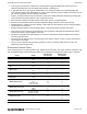
SERVICE STRATOSTEAM COUNTERTOP STEAMER Figure 27 Control Panel Parts 18 17 3 16 13 14 15 2 10 12 1 11 9 8 4 19 5 6 Key Part Number Qty 1-17 1185039 1 1 1170337 1 2 1185058 1 3 1185038 1 4 1185205 1 5 1170350 1 6 1178388 1 7 1177770 1 8 1177865 1 9 1178276 1 10 1178549 1 11 1185056 1 12 1183429 2 13 6600430 2 14 1178535 1 15 1146320 2 16 1175712 1 17 1178341 1 18 1185080 1 19 1185031 1 20 1178393 1 * 1185161 1 * Not shown on drawing.
STRATOSTEAM COUNTERTOP STEAMER SERVICE Figure 28 Heating Cartridges, Thermostats, and Contactor Parts 3 4 1 2 Key 1 2 3 4 * Quantity* Description 3D 5D CONTACTOR 208-240V 1181032 1 1 HEATER CARTRIDGE, 208V 60HZ (for Model STRE-3D) 1181501 6 HEATER CARTRIDGE, 208V 60HZ (for Model STRE-5D) 1181771 6 HEATER CARTRIDGE, 220V 50/60HZ (for Model STRE-3D) 1181502 6 HEATER CARTRIDGE, 220V 50/60HZ (for Model STRE-5D) 1181772 6 HEATER CARTRIDGE, 240V 60HZ (for Model STRE-3D) 1181503 6 HEATER CARTRIDGE, 240V 6
SERVICE STRATOSTEAM COUNTERTOP STEAMER Water Train Parts See drawing on following page. Key Part Number Qty 1-11 1184263 1 1 1185150 1 2 1185149 1 3 P4119 1 4 1184260 1 5 1176384 1 6 1174933 1 7 1184261 1 8 1184262 1 9 PP-636 1 10 PP-286 1 11 1185151 1 * P5552 1 12 1185152 1 13 P-4119 1 14 1174620 1 15 1185140 1 16 1185106 1 17 1185107 1 18 1185109 1 19 PP-439 1 20 1185108 1 * Not shown on drawing.
STRATOSTEAM COUNTERTOP STEAMER SERVICE Figure 29 Water-Train Parts See parts list on previous page.
SERVICE STRATOSTEAM COUNTERTOP STEAMER Cabinet Base Parts See drawing on following page. Key Part Number Qty 1 1183993 2 2 1183989 2 3 1183987 2 * 1182637 2 4 1183985 1 5 1183983 1 6 1183984 1 * 1183986 1 7 1184527 1 8 1185141 1 9 1185144 1 10 1185143 1 11 1185142 1 12 1172650 4 13 1146500 16 14 1146201 16 15 1174260 1 * 1174262 1 * Not shown on drawing.
STRATOSTEAM COUNTERTOP STEAMER SERVICE Figure 30 Cabinet-Base Parts See parts list on previous page.
STRATOSTEAM COUNTERTOP STEAMER Notes: PAGE 46 OF 48 OWNER’S MANUAL 1185184
STRATOSTEAM COUNTERTOP STEAMER Notes: OWNER’S MANUAL 1185184 PAGE 47 OF 48
STRATOSTEAM COUNTERTOP STEAMER StratoSteam Countertop Steamer Models STRE-3D and STRE-5D A product with the Southbend name incorporates the best in durability and low maintenance. We all recognize, however, that replacement parts and occasional professional service may be necessary to extend the useful life of this appliance. When service is needed, contact a Southbend Authorized Service Agency, or your dealer.