
User's Manual


H3-EM-66-100 Electronic Swinghandle
Operating Instructions
J-H3-EM-66-100-M_revB visit www.southco.com for latest version of this document Page 2 of 4
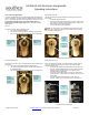
The actuator module of the swinghandle is accessed with a six-position
connector on the rear of the unit, shown below.
Pin
Description
Note
1
V
GND
ground (must be same as RFID reader
module)
2
V
SUPPLY
12 to 24 VDC power supply input (may be
connected to RFID reader V
CC
input)
3
N/C
no connect
4
Control Signal
command input (9VDC up to supply
voltage, 100 milliseconds minimum)
5
Electronic Lock
Status
open collector output (rated for V
SUPPLY
,
100mA max. load)
6
Mechanical Lock
Status
open collector output (rated for V
SUPPLY
,
100mA max. load)
The RFID reader module of the swinghandle is accessed with a four-
position connector attached to a harness connected to the module’s circuit
board. The module’s connector pinout is:
Pin
Wire Color
Description
Note
1
Black
GND
ground (must be same as actuator
module)
2
Red
VCC
12 to 24VDC power supply input
(may be connected to EML V
SUPPLY
input)
3
Green
DATA0
DATA0 output
4
White
DATA1
DATA1 output
NOTE: The mating connectors/harnesses are not provided with the
H3-EM-66-x00. Refer to Southco trade drawing J-H3-EM-66-100 for
mating connector/harness requirements.
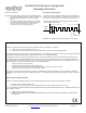
Wiegand Data Output
The RFID module will read the 4, 7, or 8 byte UID from a compatible RFID
card, and convert to Wiegand data format in reverse byte order, including
upper even parity (Pe) and lower odd parity (Po) bits, as shown below.
Control Input Signal
This signal is used to control the electronic lock slide position.
for UNLOCKED position: Supply 9VDC minimum (do not exceed
supply voltage) for at least 100 milliseconds. The lock will
remain unlocked for as long as the signal is present, or a
minimum of 3 seconds. Signal timing can typically be adjusted
at the access control device. The control signal current draw is
less than 10mA.
for LOCKED position: Supply an open contact or 0VDC (0 to
0.5V)
Electronic Lock Status Output and Mechanical Lock Status Output
Signals
Electronic Lock Status Output Signal
This output will be LOW (GND) when the lock slide is electromechanically
moved to the unlocked position. It will be in the open collector state (high-
impedance) when in the locked position.
Mechanical Lock Status Output Signal
This output will be LOW (GND) when the handle is in the open position or
when the keylock in the actuator is manually unlocked. It will be in the
open collector state (high-impedance) when in the secured position.
NOTE: These outputs are open collector outputs rated for V
SUPPLY
with
a maximum load of 100mA. To avoid damage to the H3-EM, do not
exceed voltage and current ratings.