
User's Manual

H3-EM-69-100 Electronic Swinghandle
Operating Instructions
J-H3-EM-69-100-M_revB Page 2 of 4
Wiring Diagrams
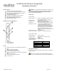
The H3-EM-69-x00 contains two separate functional modules: the actuator
module and proximity reader module. The actuator module controls and
monitors the locking function of the swinghandle.
These two modules operate independently of each other and require
connection to an access control unit (not provided), as illustrated below,
for the entire product to be fully functional.
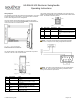
The actuator module of the swinghandle is accessed with a six-position
connector on the rear of the unit, shown below.
Pin
Description
Note
1
V
GND
ground (must be same as proximity reader
module)
2
V
SUPPLY
12 to 24 VDC power supply input (may be
connected to prox reader V
CC
input)
3
N/C
no connect
4
Control Signal
command input (9VDC up to supply
voltage, 50 milliseconds minimum)
5
Electronic Lock
Status
open collector output (rated for V
SUPPLY
,
100mA max. load)
6
Mechanical Lock
Status
open collector output (rated for V
SUPPLY
,
100mA max. load)
The proximity reader module of the swinghandle is accessed with a four-
position connector attached to a harness connected to the module’s circuit
board. The module’s connector pinout is:
Pin
Wire Color
Description
Note
1
Black
GND
ground (must be same as actuator
module)
2
Red
VCC
12 to 24VDC power supply input
(may be connected to EML V
SUPPLY
input)
3
Green
TX
data transmit
4
n/c
n/c
not connected
NOTE: If connecting the H3-EM-69’s TX data output to the DB9
connector of a computer, use the wiring configuration shown below.
NOTE: The mating connectors/harnesses are not provided with the
H3-EM-69-x00. Refer to Southco trade drawing J-H3-EM-69-100 for
mating connector/harness requirements.