
User's Manual

H3-EM-69-100 Electronic Swinghandle
Operating Instructions
J-H3-EM-69-100-M_revB Page 3 of 4
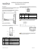
Proximity Module Data Output (TX)
The proximity module will read a compatible card and output the ASCII
code for the hexadecimal equivalent (not including parity bits). Refer to the
Specifications section for the required RS232 COM port settings.
Example: A 26-bit card with the following content is presented to the
reader:
The reader will disregard the two parity bits, and convert the remaining bits
to their hexadecimal equivalent:
F
h
6
h
0
h
0
h
2
h
0
h
The output of the reader will be the ASCII code of the hexadecimal
equivalent:
30
h
32
h
30
h
30
h
36
h
46
h
NOTE: The proximity reader will output a total of ten ASCII characters. If
the card does not support ten ASCII characters, then any unused
characters be “0” (ASCII code 30
h
).
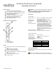
Control Input Signal
This signal is used to control the electronic lock slide position.
for UNLOCKED position: Supply 9VDC minimum (do not exceed
supply voltage) for at least 50 milliseconds. The lock will remain
unlocked for as long as the signal is present, or a minimum of 3
seconds. Signal timing can typically be adjusted at the access
control device. The control signal current draw is less than
10mA.
for LOCKED position: Supply an open contact or 0VDC (0 to
0.5V)
Electronic Lock Status Output and Mechanical Lock Status Output
Signals
Electronic Lock Status Output Signal
This output will be LOW (GND) when the lock slide is electromechanically
moved to the unlocked position. It will be in the open collector state (high-
impedance) when in the locked position.
Mechanical Lock Status Output Signal
This output will be LOW (GND) when the handle is in the open position or
when the keylock in the actuator is manually unlocked. It will be in the
open collector state (high-impedance) when in the secured position.
NOTE: These outputs are open collector outputs rated for V
SUPPLY
with
a maximum load of 100mA. To avoid damage to the H3-EM, do not
exceed voltage and current ratings.
Status LED and Output Signals
The latch is equipped with a tri-color (blue/magenta/red) LED visible from
the front of the latch. This LED provides a visible notification of the latch
status. The different latch states are described below. Please refer to the
Control Input Signal, Electronic Lock Status Output Signal, and
Mechanical Lock Status Output Signal sections for further details on
these signals.
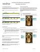
Secured
The latch is securely closed, prohibiting access.
The Status LED will be solid blue.
The electronic lock status output is at its open collector state.
The mechanical lock status output is at its open collector state.
“Secured” State
Electronically Released
The electronic lock slide is in the unlocked position and the handle can be
pulled open.
The Status LED will alternate flashing blue/magenta.
The electronic lock status output is 0V while the lock slide is in
the unlocked position.
The mechanical lock status output is at its open collector state.
“Electronically Released” State
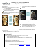
electronic
lock slide in
unlocked
position
handle
secured in
housing, cam
in locked
position
electronic lock
slide in locked
position
handle secured
in housing, cam
in locked
position