HZ1032A0TX/ HZ1032B0TX Shadowbox Wine/Bar For assistance with assembly contact: Southern Enterprises Inc. Customer Service 1-800-633-5096 service@seidal.com www.seidal.com Cabinet Assembly Instructions Due to weight, assembly requires two people. Following detailed instructions, assembly should take approximately two hours.
PACKAGE CONTENTS A M S T O S O N P W J D L S T V J S T J K F C U G Q U Y U G X J E H Q B I Z R R Z 2
PART DESCRIPTION QUANTITY PART DESCRIPTION QUANTITY A Top Panel 1 N Shelf 1 B Bottom Panel 1 O Vertical Panel 2 C Left Side Panel 1 P Vertical Panel 1 D Right Side Panel 1 Q Wine Rack Panel 4 E Shelf 1 R Leg 2 F Shelf 1 S Glass Rack Side 4 G Vertical Panel 2 T Glass Rack Middle 4 H Vertical Panel 1 U Wine Shelf 6 I Shelf 1 V Back Panel 1 J Vertical Panel 4 W Back Panel 1 K Shelf 1 X Left Door 1 L Shelf 1 Y Right Door 1 M Shelf 1
13 14 Screw 5/8” L Qty: 4 Bolt 1/2”L Qty: 14 15 Allen wrench Qty: 1 4 16 Paper cover Qty: 68
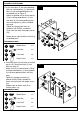
ASSEMBLY INSTRUCTIONS 1 Wood may scratch easily, please Be careful when assembling. Do not scratch. M O 1 1. Attach shelf (M), vertical panels (O) and shelf (N) by inserting wood dowels (1) into holes. O N HARDWARE USED 1 Wood Dowel x8 2. Insert cam locks (3) into holes in assembled unit on Figure 1. Screw cam bolts (2) into holes on vertical panel (P).
ASSEMBLY INSTRUCTIONS 3 3. Insert cam locks (3) into corresponding holes in assembled unit on Figure 2. Screw cam bolts (2) into corresponding holes on shelf (L). Attach shelf (L) to assembled unit on Figure 2 by inserting wood dowels (1) and cam bolts (2) into corresponding holes until shelf panel (L) and assembled unit meet. N Tighten by rotating cam locks (3) in clockwise direction with Phillips screwdriver. Cover cam lock holes with paper covers (16).
ASSEMBLY INSTRUCTIONS 5 5. Insert cam locks (3) into corresponding holes on vertical panels (J). Screw cam bolts (2) into corresponding holes on assembled unit on Figure 3. Attach assembled unit to vertical panels (J) by inserting wood dowels (1) and cam bolts (2) into corresponding holes until vertical panel (J) and assembled unit meet. Tighten by rotating cam locks (3) clockwise with Phillips screwdriver. Cover cam lock holes with paper covers (16).
ASSEMBLY INSTRUCTIONS 7 7. Insert cam locks (3) into holes in assembled parts from Figure 6. Screw cam bolts (2) into holes on vertical panel (H). Attach vertical panel (H) to assembled unit on Figure 6 by inserting wood dowels (1) and cam bolts (2) into corresponding holes until vertical panel (H) and assembled unit meet. 2 3 Tighten by rotating cam locks (3) clockwise with Phillips screwdriver. Cover cam lock holes with paper covers (16).
ASSEMBLY INSTRUCTIONS 9 9. Insert cam locks (3) into holes on vertical panel (J). Screw cam bolts (2) into holes on assembled unit on Figure 8. Attach vertical panel (J) to assembled unit on Figure 8 by inserting wood dowels (1) and cam bolts (2) into corresponding holes until vertical panel (J) and assembled unit meet. Tighten by rotating cam locks (3) clockwise with Phillips screwdriver. Cover cam lock holes with paper covers (16).
ASSEMBLY INSTRUCTIONS 11 11. Insert cam locks (3) into holes on assembled unit on Figure 9. Screw cam bolts (2) into holes on bottom panel (B). Attach bottom panel (B) to assembled unit on Figure 9 by inserting wood dowels (1) and cam bolts (2) into corresponding holes until bottom (B) and assembled unit meet. 3 Tighten by rotating cam locks (3) clockwise with Phillips screwdriver. Cover cam lock holes with paper covers (16).
ASSEMBLY INSTRUCTIONS 13 13. Attach hinges (4) to left side of panel (C) with screws (5). Note: Do not tighten the screws until step 24 is complete. 5 4 HARDWARE USED C 4 Hinge x3 5 Screw 1/2” L x 12 14. Attach hinges (4) to right side of panel (D) with screws (5). 14 Note: Do not tighten the screws until step 24 is complete.
ASSEMBLY INSTRUCTIONS 15 15. Insert cam locks (3) into holes on assembled parts from Figure 12. Screw cam bolts (2) into holes on left side panel (C). Attach left side panel (C) to assembled unit on Figure 12 by inserting wood dowels (1) and cam bolts (2) into corresponding holes. Tighten by rotating cam locks (3) clockwise with Phillips screwdriver. Repeat steps to attach right side panel (D). Cover cam lock holes with paper covers (16). This step may take two people to complete.
ASSEMBLY INSTRUCTIONS 17. Insert cam locks (3) into holes assembled unit on Figure 15. Screw cam bolts (2) into holes on top panel (A). Attach top panel (A) to assembled unit on Figure 15 by inserting wood dowels (1) and cam bolts (2) into corresponding holes until assembled unit meet. Tighten by rotating cam locks (3) clockwise with Phillips screwdriver. Cover cam lock holes with paper covers (16).
ASSEMBLY INSTRUCTIONS 19 19. As shown in Figure 19, insert assembled wine panels on Figure 18 and wine shelf (U) in assembled unit on Figure 17. This step is completed through the back of the unit. U HARDWARE USED 20 20. Attach glass rack side (S) and glass rack middle (T) to assembled unit on Figure 19 using screws (8) and wood dowels (1). 1 Tighten screws with Phillips screwdriver.
ASSEMBLY INSTRUCTIONS 21 21. Attach back panels (V) and (W) with screws (6). 6 Tighten screws with Phillips screwdriver. W HARDWARE USED 6 Screw 1/2” x 36 V 22 22. Attach metal rails (Z) to legs (R) with bolts (14) as shown in Figure 22. Tighten bolts with Allen wrench (15). R Z Don’t fully tighten bolts until Figure 23 is complete.
ASSEMBLY INSTRUCTIONS 23 23. Attach assembled unit on Figure 22 to assembled unit on Figure 21 using bolts (14). Tighten bolts with Allen wrench (15). HARDWARE USED Blot 14 x6 14 15 Allen wrench 15 24 24. Attach left door (X) and right door (Y) using screws (5). Tighten all screws with Phillips screwdriver.
ASSEMBLY INSTRUCTIONS 25 25. Attach brackets (10) to back panels using screws (13). Tighten screws using Phillips screwdriver. Mark two desired locations on wall. Drill two 3/16" holes on wall. Insert plastic anchors (12) into 2 holes in wall as shown. Tip: You may want to hammer plastic anchors into wall. Attach brackets (10) to wall using screws (9). Tighten screws (13) using Phillips screwdriver.
ASSEMBLY INSTRUCTIONS 27 27. Your Shadowbox Wine/Bar Cabinet is ready for use.
Parts Replacement Form Customer Information Name Address City/State/Zip Code Phone Number Please indicate where you purchased this item: Store/Website/Catalog Please indicate color/size/style number: Style No Parts Letter Parts Description Quantity Needed Please examine this product carefully upon immediate receipt. Any request for missing parts or damage replacement must be received within 90 days of your receipt of the product. Replacement, if available, will be honored within this time frame.