
Manual


FOR MORE INFORMATION, PLEASE CALL 210-533-1231
Revised 3/09
4110L ELECTRIC
LOCKING SYSTEM
For use where remote electric
unlocking of groups of sliding doors is
required, but door movement can be
by hand at the door. This system also
provides emergency mechanical
unlocking from a control cabinet at the
head of the door line. Doors are
locked at top and bottom in both the
open and closed positions by means of
a concealed vertical lock bar at the
rear jamb of each door. The vertical
lock bar is deadlocked at a third
locking
point inside the horizontal
cover box above the door. Standard
clear door opening widths available are
2'4" to 3'2".
FUNCTION:
ELECTRIC - Individual switches located
on a remote control panel operate an
electric motor housed in the horizontal
cover box over each door, raising the
vertical lock bar and unlocking the door.
Upon unlocking, the door springs open
a few inches. All door movement is by
hand at the door, which automatically
snap/deadlocks when moved to the fully
closed or fully open position. Individual
lamp indicators on the control panel
show locked/unlocked condition.
A single switch can provide
group unlocking.
MECHANICAL - In the absence of
electrical power, doors may be
individually unlocked with a manual
release tool. Door movement is by
hand and door will relock in either fully
open or closed position.
EMERGENCY GANG RELEASE
- In
an emergency, all doors in a cell line
may be simultaneously unlocked
from a mechanical release cabinet
at the end of the cell line. While in
emergency release mode, doors
will not relock in any position.
4110L
ELECTRIC LOCKING
SYSTEM
TECHNICAL DATA:
• COVER BOX:
1' 0-3/4" H x 7-1/8" D
• COVER BOX MATERIAL:
7 gauge steel plate
• HINGED PANEL:
10 gauge steel
• DOOR ROLLERS:
3" diameter, machined
steel with sealed bearings
• VERTICAL LOCK BAR
DIMENSIONS:
5/8" SQ
by full height
of door
•
FINISH: Prime paint
•
DOOR HANGER:
7 gauge steel plate
•
ELECTRICAL:
Motor:
1/60 HP, 115 VAC,
60 Hz., single phase power,
Inrush: .7A
Locked Rotor Current: .8A
•
WIRE REQUIREMENTS:
When electric operation of the
door is from a remote station, a
minimum of five conductors
(minimum 14 gauge) are
required between the control
point and the door, except for
those models having the letter
“K” (keyswitch) in the suffix.
Keyswitch models require
minimum six conductors.
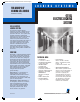
L O C K I N G S Y S T E M S
FOR GROUPS OF
SLIDING CELL DOORS
Maximum
security.
B25
090604SouthernFolger_final:INSIDE 8/21/09 5:22 PM Page 35