
Installation Instructions

SOYAL
ACCESS CONTROL SYSTEM
®
AR-323-D
V200615
Smart Digital Door Lock
RF Card
- 2 -
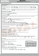
P.S. Once MASTER CARD is presented after one
warning beep, all card data will be cleared.
5 short beeps after 5sec: cards cleared4.
1 2 3
4 5 6
7 8
0 #
*
9
Z
Z
Y
X
A
B
B
C
A
A
B
B
C
C
D
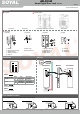
Handle hole
Deadbolt knob hole
Cylinder hole
Cable hole
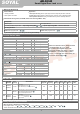
9.Elastic Spring
10.Allen Wrench
11.Screw
12. Strike Box
13. Strike Plate
14. Front Panel
15. Back Panel
X CN1
Y CN2
Z CN3
5.Cylinder Lock
6.Mechanical Key
7. Waterproof Strap
8.Handle Screw
1.Mortise
2.Mortise Plate (mounted)
3.Spindle of Knob
4.Spindle of Handle
5.
1.
11.
11.
4.
3.
2.
15.
7.
8.
8.
9.
9.
7.
6.
10.
Cross-Head screw driver
Tools
11.
12. 13.
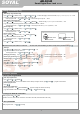
(1)Stand-alone: Install battery before the upper cover of
back panel.
(2)Install the lower cover of back panel as above picture
shown.
(3)Install the lower cover of front panel.
(1)
Make sure position and right hole direction for Strike box.
1. 2. 3.
115.87
20*10
115.87
20*10
115.87
20*10
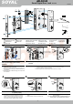
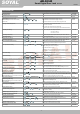
Paste hole-sticker on the door properly and
make cuts depending on hole-stickers
dimension.
Install cylinder into mortise , use the screw to
fix cylinder properly
Installation Mortise plate
Take away mortise plate , embed mortise into door frame and fix it with screws
properly.
Insert the spindle of handle separately into
the handle hole of mortise.
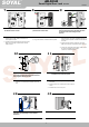
Installation front and back panel.
Installation Strike and Strike box
The spindle of handle insert deadbolt knob
hole, front and back panel clamped and fixed
on the door with inner hexagon screw
properly.
Connect connector of reader to the front
panel and the mortise lock.
Use tools "Plastic PICK" to guide rubber pad
to fit with front and back panel and then fixed
them together with the screws.
Paste hole-sticker on the doorframe properly
and make cuts depending on hole-stickers
dimension.
(1)Only make "deadbolt knob hole" from inner door to
mortise, don't cross to outer door.
(2)Make sure accurate position & right hole direction of
striker plate; before making cuts, latch bolt position can
be made firstly.
(3)Networking mode : Additional hinge cuts is required for
PC connection.
(1)Check the correct direction of mortise with latch download before fixed.
(2)Prepare in advance connector of reader
(3)Wire the power and communication cable to the hole of the door
115.87
20*10
7. 8.
4. 5. 6.
9.
10.
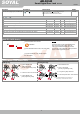
(1)The depth of cylinder is not too deep or too shallow ,
we suggest to check inserted depth by the side of
mortise , make sure that the position of lock picks
must be over first screw and between screw and
screw holes to ensure cylinder operate normally.
(1)Make sure the key lock hole on the topside,and fixed
tightly.
(2)Please confirm the key can control 2 bolt.
※ It is normal for the key lock hole to slightly
have recessed arc
(1)Please read "warning sticker" before install the
rotated type of mortise, follow arrow direction to
insert spindle of handle.
(2)Spindle of handle are divided into longest and short
edge, insert short edge to squre hole at the both
sides of mortise.
(1)Connect the front panel connector to mortise.
(2)Plug in the connector of reader to the front panel
(1)Before fix front and back panel with the screw ,
make sure to fit metal base and rubber pad on the
door.
(1)The spindle of knob insert to deadbolt knob hole of
back panel firstly, then insert to deadbolt knob hole of
mortise; finally the spindle of handle insert handle hole
of mortise.
(2)Please insert the connector cable from the interior
(CN2) into the hole that connected to interior door lock.
(3)Connect the power and communication cable (CN1) to
DC power and RS485 communication.
(Refer to the cable description)
(1)
(2)
(3)
E
E
E
D
F
G
Handle screw hole
Mortise hole
Strike hole
4.
14.
1 2 3
4 5 6
7 8
0 #
*
9
1 2 3
4 5 6
7 8
0 #
*
9
Connector of mortise
Connector of reader
1 2 3
4 5 6
7 8
0 #
*
9
CN1
CN2
(Front panel) (Back panel)
(3)
(1)
(1)
(2)
(3)
(2)
(2)