6KB 82440 LX PCI Mainboard User’s Guide & Technical Reference
® ™ About This Guide This UserÕs Guide is for assisting system manufacturers and end users in setting up and installing the mainboard. Information in this guide has been carefully checked for reliability; however, no guarantee is given as to the correctness of the contents. The information in this document is subject to change without notice. Copyright Notice Copyright 1997, Soyo Computer Inc. All rights reserved. This manual is copyrighted by Soyo Computer Inc.
iii Table of Contents Chapter 1: Introduction .................................................. 1 Key Features ............................................................................... 1 Unpacking the Mainboard ........................................................... 2 Electrostatic Discharge Precautions............................................ 2 Mainboard Layout w/ Default Settings ....................................... 3 Chapter 2: Hardware Setup ...........................................
iv Chapter 3: BIOS Setup .................................................. 19 Standard CMOS Setup .............................................................. 20 BIOS Features Setup ................................................................. 21 Chipset Features Setup.............................................................. 23 Power Management Setup ........................................................ 26 PNP/PCI Configuration Setup ..................................................
1 Introduction The 82440 LX PCI mainboard is a high-performance ATX architecture system board that supports 686 (PII) family CPUs. This mainboard is fully compatible with industry standards, and adds many technical enhancements.
2 Introduction Unpacking the Mainboard The mainboard package contains: ¥ ¥ ¥ The 82440LX Mainboard This User's Guide One Triones IDE Bus Master Drivers Diskette Note: Do not unpack the mainboard until you are ready to install it. Follow the precautions below while unpacking the mainboard. 1. Before handling the mainboard, ground yourself by grasping an unpainted portion of the systemÕs metal chassis. 2.
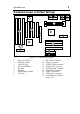
3 Introduction Mainboard Layout w/ Default Settings 11 11 12 3 15 15 1 6 5 2 8 16 2 7 17 10 4 9 9 Figure 1Ð1. Mainboard Layout 1. 2. 3. 4. 5. 6. 7. 8. Slot 1 for PII CPU 82440LX Chipset Ultra I/O Chip PnP FLASH BIOS ISA Slot PCI Slot DIMM Memory Bank AGP Port 9. 10. 11. 12. 13. 14. 15. 16. 17.
4 Introduction Default settings are as follows: 686 (PII) 233MHz CPU, On-board PCI Bus IDE Enabled, FDC Enabled, 2 high speed UARTS Enabled (w/ 16550 FIFO), 1 EPP/ECP port (ECP + EPP mode), and ATX Power Supply. 1 JP44 IR 1 6 5 10 COM2 COM1 PRT 83977FX USB1 USB2 PS/2 Mouse Conn.
2 Hardware Setup This chapter explains how to configure the mainboardÕs hardware. After you install the mainboard, you can set jumpers, install memory on the mainboard, and make case connections. Refer to this chapter whenever you upgrade or reconfigure your system. CAUTION: Turn off power to the mainboard, system chassis, and peripheral devices before performing any work on the mainboard or system.
6 Hardware Setup SW1: Bus Fraction Core/Bus Ratio Select Jumper Set this jumper according to your CPU clock. Ratio 686 (PII) Family SW1 ON 3.5x (default) 686 (PII) Ð 233 MHz 4.0x 686 (PII) Ð 266 MHz 1 2 3 4 5 ON 1 2 3 4 5 ON 4.5x 686 (PII) Ð 300 MHz 12345 ON 5.0x 686 (PII) Ð 330 MHz 12345 CPU Type Configuration Set the mainboardÕs CPU switch SW1 according to CPU type as described below. 686 (PII) Ð 233 CPU Settings (3.5 x clock) FLASH BIOS SW1 ON 1 2 3 4 5 Figure 2Ð1Ð1.
7 Hardware Setup 686 (PII) Ð 266 CPU Settings (4.0 x clock) FLASH BIOS SW1 ON 1 2 3 4 5 Figure 2Ð1Ð2. CPU Jumper Settings 686 (PII) Ð 300 CPU Settings (4.5 x clock) FLASH BIOS SW1 ON 1 2 3 4 5 Figure 2Ð1Ð3. CPU Jumper Settings 686 (PII) Ð 330 CPU Settings (5.0 x clock) FLASH BIOS SW1 ON 1 2 3 4 5 Figure 2Ð1Ð4. CPU Jumper Settings Memory Configuration The mainboard supports four banks of 168-pin 3.3V EDO/SDRM Unbuffered DIMM.
8 Hardware Setup Multi I/O Port Addresses Default settings for multi-I/O port addresses are shown in the table below. Port I/O Address IRQ Status LPT1* 378H 7 ECP + EPP COM1 3F8H 4 COM2 2F8H 3 * If default I/O port addresses conflict with other I/O cards (e.g. sound cards or I/O cards), you must adjust one of the I/O addresses to avoid address conflict. (You can adjust these I/O addresses from the BIOS. Note: Some sound cards have a default IRQ setting for IRQ7, which may conflict with printing functions.
9 Hardware Setup PS/2 Mouse Connector A six-pin female PS/2 mouse connector is located at the rear of the board. Plug the mouse jack into this connector. IR – IR Connector A ten-pin wafer connector is for connecting to the IR device. Use the device that has the ASKIR or HPSIR specification and choose ASKIR/HPSIR from the BIOS setup. IR Connector Pin Assignment VCC 1 6 Empty FIRRX 2 7 CIRRX IRRX 3 8 VSB GND 4 9 Empty IRTX 5 10 Empty There are two ways to use this IR function.
10 Hardware Setup IDE1/IDE2 – On-board Primary/Secondary IDE HDD Connectors Attach on-board hard disk drives to these connectors. COM1/COM2 Connectors Connect COM1/COM2 devices to these connectors. IDE LED – IDE HDD LED Connectors Attach on-board IDE device LEDs to this connector. The LED lights when an IDE device is active. FDC Connector Attach floppy cable to this connector. PRT – Parallel Port Connector Attach parallel port cable to this connector.
11 Hardware Setup FAN: CPU Cooling Fan Connector This 3-pins connector provides 12V power for the CPU cooling fan which matches the pin assignment of this connector. If you enable the Suspend Mode function in BIOS setup, this fan will stop when the system is into the suspend mode.
12 Hardware Setup Slot 1 Installation Guide This mainboard provides a non-boxed 686 (PII) CPU retention set to secure the CPU on this board. Follow the steps below to secure this type of CPU on to your motherboard. Step 1: Find the ATX PW and the Slot 1 on the board and set the board in the direction as follows before doing any installation. Slot 1 (for Pentium II CPU) ATX PW Install the 2 pairs of screws, as shown in the following figure, from the bottom of the motherboard upward onto the mainboard.
13 Hardware Setup Step 2: Insert the supporting base, which is shown below, into the two holes directly to the left of the 2 sets of screws that have just been inserted on to the board.
14 Hardware Setup Step 3: Insert the 2 latches into the two holes of the supporting base and then turn them 90¡ to secure the CPU.
15 Hardware Setup Step 4: Set the retention clip right on the top of the 2 sets of screws which are along the sides of Slot1 and then tighten the 4 screws on the retention clip.
16 Hardware Setup Step 5: Insert the CPU into the retention clip and notice that the heat sink is on the left hand side of the board. Lock the two latches on the sides of the CPU to secure the CPU.
17 Hardware Setup Step 6: Insert the clip portion of the CPU supporter, which is shown below, so that the heat sink can sit on the top of the whole CPU supporter.
3 BIOS Setup The mainboardÕs BIOS setup program is the ROM PCI/ISA BIOS from Award Software Inc. Enter the Award BIOS programÕs Main Menu as follows: 1. Turn on or reboot the system. After a series of diagnostic checks, you are asked to press DEL to enter Setup. 2. Press the key to enter the Award BIOS program and the main screen appears: ROM PCI/ISA BIOS CMOS SETUP UTILITY AWARD SOFTWARE, INC.
19 BIOS Setup Standard CMOS Setup Run the Standard CMOS Setup as follows. 1. Choose ÒSTANDARD CMOS SETUPÓ from the Main Menu. A screen appears. ROM PCI/ISA BIOS STANDARD CMOS SETUP AWARD SOFTWARE, INC. Date (mm:dd:yy) : Fri, Feb 1 1995 Time (hh:mm:ss) : 7 : 30 : 33 HARD DISKS Primary Master Primary Slave Secondary Master Secondary Slave TYPE : : : : SIZE AUTO None None None 0 0 0 0 Drive A : 1.44M, 3.5 in.
20 BIOS Setup Video Choose Monochrome, Color 40x25, VGA/EGA (default), Color 80x25 Floppy 3 Mode Support Choose Disabled (default) or Enabled. When enables this function, the system will support 720KB/1.25MB/1.44MB 3 different modes floppy diskette. Note: This function is for a special disk drive which happens to be popular in Japan. Halt On Choose halt mode when BIOS detects system errors: All Errors (default) All, But Diskette No Errors All, But Keyboard All, But Disk/Key 3.
21 BIOS Setup BIOS Features Setup Run the BIOS Features Setup as follows. 1. Choose ÒBIOS FEATURES SETUPÓ from the Main Menu and a screen with a list of items appears. (The screen below shows the BIOS default settings.) ROM PCI/ISA BIOS BIOS FEATURES SETUP AWARD SOFTWARE, INC.
22 Boot Sequence BIOS Setup Choose the boot device sequence as your need. For example, ÒA, C, SCSIÓ means that BIOS will look for an operating system first from drive A, drive C, then SCSI device. Options of this function are: A, C, SCSI; C,A, SCSI; C, CD-ROM, A; CD-ROM, C, A; D, A, SCSI; E, A, SCSI; F, A, SCSI; SCSI, A, C; SCSI, C, A; C only; LS120, C. Swap Floppy Drive Enabled changes the sequence of the A: and B: drives. (The Default setting is Disabled.) Boot Up Num Lock Status Choose On or Off.
23 BIOS Setup PCI/VGA Palette Snoop Enabled: The color of the monitor may be incorrect if uses with MPEG card. Enable this option to make the monitor normal. Disabled: Default setting. OS Select for DRAM >64MB OS2: Choosing this when you are using OS/2 operation system. Non-OS/2: Choosing this when you are using noOS/2 operation system. Video or Adapter BIOS Shadow BIOS shadow copies BIOS code from slower ROM to faster RAM. BIOS can then execute from RAM.
24 BIOS Setup Chipset Features Setup The Chipset Features Setup option changes the values of the chipset registers. These registers control system options in the computer. Note: Change these settings only if you are familiar with the Chipset. Run the Chipset Features Setup as follows. 1. Choose ÒCHIPSET FEATURES SETUPÓ from the Main Menu and the following screen appears. (The screen below shows default settings.) ROM PCI/ISA BIOS CHIPSET FEATURES SETUP AWARD SOFTWARE, INC.
25 BIOS Setup EDO RAS# Precharge Time Use the default setting. EDO DRAM Read Burst Use the default setting. DRAM Write Burst Use the default setting. DRAM Data Integrity Mode Choose Non-ECC (default) or ECC according to the DRAM type you have. CPU-TO-PCI IDE Posting Use the default setting. System BIOS Cacheable Disabled: The ROM area F0000HFFFFFH is not cached. Enabled: The ROM area F0000HFFFFFH is cacheable if cache controller is enabled.
26 BIOS Setup SDRAM RAS-to-CAS Delay Use the default setting. SDRAM RAS Precharge Time Use the default setting. SDRAM CAS Latency Time Use the default setting. Spread Spectrum Modulated Enabled it when you want to run the FCC or DOC testing. CPU Warning Temperature Choose Disabled (default) or Enabled. Set CPU temperature from 50¼C to 70¼C. The system will slow down automatically when CPU temperature goes beyond the preset value.
27 BIOS Setup Power Management Setup The Power Management Setup option sets the systemÕs power saving functions. Run the Power Management Setup as follows. 1. Choose ÒPOWER MANAGEMENT SETUPÓ from the Main Menu and a screen with a list of items appears.
28 BIOS Setup PM Control by APM Choose Yes or No (default). APM stands for Advanced Power Management. To use APM, you must run Òpower.exeÓ under DOS v6.0 or later version. Video Off Method Choose V/H Sync+Blank (default), Blank screen, or DPMS for the selected PM mode. Doze Mode When the set time has elapsed, the BIOS sends a command to the system to enter doze mode (system clock drops to 33MHz). Time is adjustable from 1 Min to 1 Hour. Standby Mode The default is Disabled.
29 BIOS Setup PNP/PCI Configuration Setup This option sets the mainboardÕs PCI Slots. Run this option as follows: 1. Choose ÒPNP/PCI CONFIGURATION SETUPÓ from the Main Menu and the following screen appears. (The screen below shows default settings.) ROM PCI/ISA BIOS PNP/PCI CONFIGURATION AWARD SOFTWARE, INC.
30 BIOS Setup IRQX and DMAX assigned to Choose PCI/ISA PnP or Legacy ISA. If the first item is set to Manual, you could choose IRQX and DMAX assigned to PCI/ISA PnP card or ISA card. PCI/ISA PnP: BIOS auto assigns IRQ/DMA to the device. Legacy ISA: User assigns IRQ/DMA to the device. PCI IRQ Activated By Choose Edge or Level. Most PCI trigger signals are Level. This setting must match the PCI card.
31 BIOS Setup Load BIOS Defaults Choose this item and the following message appears: ÒLoad BIOS Defaults (Y/N)?NÓ To use the BIOS defaults, change the prompt to ÒYÓ and press . Note: BIOS DEFAULTS values are adjusted for high performance. If you run into any problems after loading BIOS DEFAULTS, please load the SETUP DEFAULTS for the stable performance. Integrated Peripherals The Integrated Peripherals option changes the values of the chipset registers.
32 BIOS Setup IDE HDD Block Mode Choose Enabled (default) or Disabled. Enabled invokes multi-sector transfer instead of one sector per transfer. Not all HDDs support this function. IDE Primary Master PIO IDE Primary Slave PIO IDE Secondary Master PIO IDE Secondary Slave PIO Choose Auto (default) or mode 0~4. Mode 0 is the slowest speed, and HDD mode 4 is the fastest speed. For better performance and stability, we suggest you use the Auto setting to set the HDD control timing.
33 BIOS Setup Onboard Parallel Port Choose the printer I/O address: 378H/IRQ7 (default), 3BCH/IRQ7, 278H/IRQ5 Onboard Printer Mode Choose SPP, ECP, EPP/SPP, or ECP/EPP mode. The mode depends on your external device that connects to this port. ECP Mode Use DMA Choose 3 (default) or 1 to select DMA3 or DMA1 when using the ECP device. Parallel Port EPP Type Choose EPP specification Ver. 1.7 (default) or 1.9. USB Controller Enable it when you are using the USB device.
34 BIOS Setup Supervisor Password Based on the setting you made in the ÒSecurity OptionÓ of the ÒBIOS FEATURES SETUPÓ, this Main Menu item lets you configure the system so that a password is required every time the system boots or an attempt is made to enter the Setup program. Change the password as follows: 1. Choose ÒSUPERVISOR PASSWORDÓ in the Main Menu and press . The following message appears: ÒEnter Password:Ó 2. Enter a password and press .
35 BIOS Setup User Password Based on the setting you made in the ÒSecurity OptionÓ of the ÒBIOS FEATURES SETUPÓ, this Main Menu item lets you configure the system so that a password is required every time the system boots or an attempt is made to enter the Setup program. Change the password as follows: 1. Choose ÒUSER PASSWORDÓ in the Main Menu and press . The following message appears: ÒEnter Password:Ó 2. Enter a password and press .
36 BIOS Setup IDE HDD Auto Detection This Main Menu item automatically detects the hard disk type and configures the STANDARD CMOS SETUP accordingly. Note: This function is only valid for IDE hard disks. ROM PCI/ISA BIOS CMOS SETUP UTILITY AWARD SOFTWARE, INC.
4 Drivers Installation Guide Triones IDE Bus Master Drivers Installation Guide is for Intel PIIX/PIIX3 Chipset. MS-DOS/WINDOW/WFW 1) You should install CD-ROM in secondary channel in Windows (WFW). 2) Change the current directory to a: or b:. 3) Under DOS command line prompt, run the SETUP directly. After entering the setup utility, just follow the instructions of the setup. WINDOWS NT3.5/4.0 1) From the Program Manager, double click on ÒWindows NT SetupÓ in the Main group.
38 Drivers Installation Guide WINDOWS 95 1) Close any running applications. 2) Insert the floppy disk into drive A:. 3) Open ÒMy ComputerÓ, double click ÒDrive A:Ó. 4) Double click ÒWin95Ó. 5) Double click the Setup program. 6) Then just follow the instruction. NOVELL 3.X&4.X 1) Copy the driver TRIN4X.DSK or TRIN312.DSK to the subdirectory which holds the file SERVER.EXE. 2) Boot up the file server. 3) On the system console and on the command prompt state, type in: load TRIN4X.
Drivers Installation Guide 39 4) From root directory, type the following commands: mkdir/inst cd /inst tar xvf /tmp/trisco.tar. (Note: there is a period at the end of the last command.) 5) Now, insert a blank diskette into the floppy drive A and type: tar cvf /dev/. (Note: there is a period at the end of the last command.) Your floppy drive A device name could be: ¥ rfd096ds15,5.25 DSHD ¥ rfd0135ds18 3.5 DSHD ¥ rfd048ds9 5.25 DSDD ¥ rfd0135ds9 3.
40 Drivers Installation Guide 4) From root directory, type the following commands: mkdir/inst cd /inst tar xvf /tmp/trisco.tar. (Note: there is a period at the end of the last command.) 5) Install the driver by typing: ./install 6) Reboot your SCO UNIX system.. OS/2 2.0 and WARP 3.X 1) Copy TRIOS2.ADD from the floppy diskette to your hard disk under the OS2 directory (i.e., C:\OS2). 2) Edit C:\CONFIG.SYS to replace BASEDEV=IBM1S506.ADD with BASEDEV=TRIOS2.ADD 3) Reboot the system.
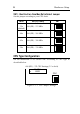
41 Quick Installation Guide Quick Installation Guide This Quick Installation Guide leaflet is designed for those people who are familiar with motherboard settings to set up this new motherboard in order to boot up the system. Refer back to the proper chapters if you have run in to any problems. Motherboard Layout 1 JP44 IR 1 6 5 10 COM2 COM1 PRT 83977FX USB1 USB2 PS/2 KB Conn. PS/2 Mouse Conn.
42 Quick Installation Guide Memory Configurations DIMM BANKS DIMM1 DIMM2 DIMM3 EDO/SDRAM RAM Type Size DIMM4 8/16/32/64/128 Note: This mainboard requires 3.3V DIMM with an access time of 70ns or less, it supports memory size from 8 to 512MB and you may use any combination of DIMMs in the banks. Connectors and Jumper Settings CMOS clear: JP5 ATX Power Supply: ATX CPU Cooling Fan: FAN Retain CMOS data (default) 1-2 please insert the ATX power supply plug into this header.