
user manual

SY-6VBA 133 Quick Start Guide
8
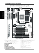
Hardware
Installation
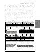
Step 3. Configure Memory
Your board comes with four DIMM sockets, providing support for up to 1.5GB of main
memory using unbuffered and registered DIMM modules from 8MB to 256/512MB. On this
motherboard, DRAM speed can be set independent from the CPU front side bus speed.
Depending on the DRAM clock speed setting in the BIOS setup (Chapter 3), appropriate
memory modules must be used. For 66MHz DRAM speed, use PC66 memory; for 100MHz
DRAM speed, use PC100 memory; for 133MHz DRAM speed, use PC133 memory.
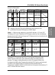
Memory Configuration Table
Number of
Memory Modules
DIMM 1 DIMM 2 DIMM 3 DIMM 4
1 1
st
2 2
nd
1
st
3 3
rd
2
nd
1
st
4 4
th
3
rd
2
nd
1
st
RAM Type SDRAM
Memory Module
Size (MB)
8/16/32/64/128/256/512 MB
(For DIMM1& DIMM2)
8/16/32/64/128/256 MB
(For DIMM3 & DIMM4)
Note:Always install memory modules in the order prescribed in this table.
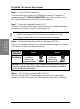
Step 4. CPU B21 and A14 Settings: JP8 and JP9
For certain Intel CPUs, the multiplier is not locked such that setting a multiplier higher than
specified on the CPU is possible. For technical details read the following:
Your PII /III 100/66 MHz FSB CPU has an input pin B21 (100/66# signal) to tell it what FSB
frequency it is running at; The PIII 133 MHz FSB CPU has two pins B21and A14 (133/100#
signal). JP8 and JP9 are connected to the B21 and A14 input respectively and are used to
tell CPU its FSB speed.
The actual FSB Frequency is however set through the BIOS and it may therefore differ from
the Frequency specified to the CPU through JP8 & JP9.
Because some INTEL CPUs have their multipliers limited at a FSB Frequency of 100MHz
and higher, telling the CPU that it is running at 66MHz through JP8 & JP9 while setting a
different (higher) FSB Frequency in the BIOS may allow the user to set a higher multiplier
value. Doing so will however force your CPU to operate out of its specifications, and therefore
SOYO can not guarantee the proper functioning of your system.