SY-7ISA+ Motherboard **************************************************** FC-PGA Socket 370 Processor supported 815E AGP/PCI/CNR 66/100/133 MHz Front Side Bus supported ATX Form Factor **************************************************** User's Manual
SOYO ™ SY-7ISA+ Copyright © 2000 by Soyo Computer Inc. Trademarks: Soyo is the registered trademark of Soyo Computer Inc. All trademarks are the properties of their owners. Product Rights: All names of the product and corporate mentioned in this publication are used for identification purposes only. The registered trademarks and copyrights belong to their respective companies. Copyright Notice: All rights reserved. This manual has been copyrighted by Soyo Computer Inc.
Table of Contents SY-7ISA+ Table of Contents CHAPTER 1 MOTHERBOARD DESCRIPTION ...................................1 1-1 1-2 1-3 1-4 1-5 1-6 1-7 1-8 1-9 INTRODUCTION ............................................................1 HANDLING THE MOTHERBOARD ..............................3 ELECTROSTATIC DISCHARGE PRECAUTIONS .........3 SY-7ISA+ MOTHERBOARD LAYOUT..........................4 SY-7ISA+ MOTHERBOARD COMPONENTS ...............5 CHIPSET ..................................................................
Table of Contents 3-5 3-6 3-7 3-8 3-9 3-10 3-11 3-12 3-13 SY-7ISA+ INTEGRATED PERIPHERALS .....................................69 POWER MANAGEMENT SETUP ................................74 PNP/PCI CONFIGURATION SETUP.............................78 PC HEALTH STATUS....................................................81 LOAD FAIL-SAFE DEFAULTS.....................................83 LOAD OPTIMIZED DEFAULTS...................................84 SUPERVISOR PASSWORD...........................................
Motherboard Description SY-7ISA+ Chapter 1 MOTHEBOARD DESCRIPTION 1-1 INTRODUCTION Ø Ø The SY-7ISA+ AGP/PCI/CNR Motherboard is a high-performance Socket 370 processor supported ATX form-factor system board. SY7ISA+ uses the 815E Chipset technology. This Motherboard is fully compatible with industry standards Supports Intel ® FC-PGA processors - FSB 66MHz: Celeron(400-700MHz) - FSB 100MHz: Pentium ® III (500E-850MHz) - FSB 133MHz: Pentium ® III (533-1.
Motherboard Description SY-7ISA+ Ø Battery Low voltage Detection Ø Supports multiple-boot function Ø AGP 2.0 Compliant; AGP Universal Connector supports: - 1.5V and 3.3V AGP cards - 1X/2X/4X data transfer Ø Supports Communication Networking Riser Slot (CNR 1.
Motherboard Description 1-2 SY-7ISA+ HANDLING THE MOTHERBOARD To avoid damage to your Motherboard, follow these simple rules while unpacking: Ø Before handling the Motherboard, ground yourself by grasping an unpainted portion of the system's metal chassis. Ø Remove the Motherboard from its anti-static packaging. Hold the Ø Motherboard by the edges and avoid touching its components. Check the Motherboard for damage. If any chip appears loose, press carefully to seat it firmly in its socket.
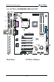
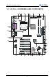
Motherboard Description SY-7ISA+ 1-4 SY-7ISA+ MOTHERBOARD LAYOUT PS/2 KB PS/2 Mouse Connector Connector 3 1 ATX Power JP1 1 USB 1 3 JP34 JP6 JP7 USB 2 1 2 1 1 3 3 CJ1 CJ2 1 2 PRT COM A IDE 2 IDE 1 VGA JOYSTICK 1 3 LINE-OUT CPUFAN LINE-IN CDIN1 DIMM3 4 DIMM1 1 DIMM2 AGP Slot MIC JACK PCI#1 FDC1 Intel Sigmatel STAC9721 PCI#2 JP10 PCI#3 WOL Header JP5 ITE IT8712F-A PCI#4 1 CMOS Clear Jumper 3 1 Power LED Reset JP33 PCI#5 3V Lithium Battery 1 2 JP9 PCI#6 1 2
Motherboard Description SY-7ISA+ 1-5 SY-7ISA+ MOTHERBOARD COMPONENTS A B C D E F G H I J AG AF AE K AD L M N O P Q AC AB AA Z 5 Y X V U T S R
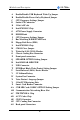
Motherboard Description A B C D E F G H I J K L M N O P Q R S T U V W X Y Z AA AB AC AD AE AF AG SY-7ISA+ Enable/Disable USB Keyboard Wake Up Jumper Enable/Disable Power-On by Keyboard Jumper CPU Frequency Settings Jumper Socket 370 Connector 32-bit AGP slot Intel FW82815 Chip ATX Power Supply Connector DIMM Bank CPU Frequency Settings Jumper Bus Mastering E-IDE/ATAPI Ports Floppy Disk Drive (FDD) Intel FW82801 Chip CMOS Clear Jumper Wake-On-LAN( WOL) Header Chassis Cooling Fan Connector Front panel conn
Motherboard Description SY-7ISA+ 1-6 CHIPSET The Intel ® 815E Chipset is a high-flexibility chipset designed to extend from the basic graphics/multimedia PC platform up to the mainstream performance desktop platform. The chipset consists of a Graphics and Memory Controller Hub (Intel ® 815E GMCH), an I/O Controller Hub2 (ICH2) for the I/O subsystem, and a Firmware Hub(FWH). The Intel ® 815E GMCH integrates a system memory SDRAM controller that supports a 64-bit 100/133 MHz SDRAM array.
Motherboard Description l l l l l l l SY-7ISA+ Enhanced DMA Controller, Interrupt Controller & Timer Functions Bus Master IDE controller – Supports Ultra ATA/100 USB host interface with support for 4 USB ports AC’97 2.1 interface Low Pin Count (LPC) interface Firmware Hub(FWH)interface support Alert On LAN l l l SIM Bus controller I/O APIC Upstream accelerated hub architecture interface for access to the GMCH 1-6.
Motherboard Description SY-7ISA+ requests on the host bus). Host bus addresses are decoded by the Intel ® 815E GMCH for accesses to system memory, PCI memory and PCI I/O (via hub interface), PCI configuration space and Graphics memory. The Intel ® 815E GMCH takes advantage of the pipelined addressing capability of the pipelined addressing capability of the processor to improve the overall system performance. The Intel ® 815E GMCH supports the 370-pin socket processor. *370-pin socket (PGA370).
Motherboard Description SY-7ISA+ 1-6.5 Multiplexed AGP and Display Cache Interface The Intel ® 815E GMCH multiplexes an AGP interface with a display cache interface for internal 3D graphics performance improvement. The Display Cache is used only in the internal graphics. When an AGP card is installed in the system, the Intel ® 815E GMCH internal graphics will be disabled and the AGP controller will be enabled. 1-6.5.
Motherboard Description SY-7ISA+ interface are allowed. 1-6.5.2 AIMM Card Interface Display Cache Interface multiplexed on the AGP interface: l 32-bit data interface l 133 MHz SDRAM interface only l Flexible AGP In-Line Memory Module (AIMM) Implementation l Support for 2 1Mx16, or 1 2Mx32 on AIMM card l 4MB max addressable 1-6.5.3 Display Cache Interface The Intel ® 815E GMCH support a Display Cache SDRAM controller with a 32-bit 133 MHz SDRAM array.
Motherboard Description SY-7ISA+ set of 3D instructions permit these features to be independently enabled or disabled. For the Intel ® 815E GMCH, a Display Cache (DC) can be used for the Z-buffer is located in system memory. The Intel ® 815E GMCH integrated graphics accelerator’ s 2D capabilities include BLT and arithmetic STRBLT engines, a hardware cursor and an extensive set of 2D registers and instructions.
Motherboard Description SY-7ISA+ 1-6.8 IDE Support The motherboard has two independent bus-mastering PCI IDE interfaces. These interfaces support PIO Mode3, PIO Mode 4, PIO Mode 5 ATAPI devices (e.g., CD-ROM), and Ultra DMA 33/66/100 synchronous-DMA mode transfers. The BIOS supports logical block addressing (LBA) and extended cylinder head sector (ECHS) translation modes. The BIOS automatically detects the IDE device transfer rate and translation mode.
Motherboard Description SY-7ISA+ 1-6.9 Real-Time Clock The real-time clock supports 256 bytes of battery-backed CMOS SRAM. Hardware implementation to indicate century rollover.
Motherboard Description SY-7ISA+ program, the diskette drive interface can be configured for the following diskette drive capacities and sizes. l 360 KB, 5.25-inch l 1.2 MB, 5.25-inch l 720 KB, 3.5-inch l 1.2 MB. 3.5-inch (driver required) l 1.25-1.44 MB, 3.5-inch l 2.88 MB, 3.5-inch 1-7.4 PS/2 Keyboard and Mouse Interface PS/2 keyboard and mouse connectors are located on the back panel of the motherboard.
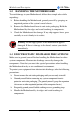
Motherboard Description SY-7ISA+ 1-8 HARDWARE MONITOR The optional hardware monitor subsystem provides low-cost instrumentation capabilities. The features of the hardware monitor subsystem include: Ø An integrated ambient temperature sensor Ø Fan speed sensors, which monitor the fan 1 and fan 2 connectors Ø Power supply voltage monitoring to detect levels above or below acceptable values When suggested ratings for temperature, fan speed, or voltage are exceeded, an interrupt is activated.
Hardware Installation SY-7ISA+ Chapter 2 HARDWARE INSTALLATION Congratulations on your purchase of SY-7ISA+ Motherboard. You are about to install and connect your new Motherboard. Note: Do not unpack the Motherboard from its protective antistatic packaging until you have made the following preparations. 2-1 PREPARATIONS Gather and prepare all the following hardware equipment to complete the installation successfully: 1. Socket 370 processor with built-in CPU cooling fan.
Hardware Installation 2-2 SY-7ISA+ UNPACKING THE MOTHERBOARD When unpacking the Motherboard, check for the following items: u The SY-7ISA+ 815E AGP/PCI/CNR Motherboard u This Quick Start Guide u The Installation CD-ROM u SOYO Bonus Pack CD-ROM u One IDE Device ATA 100 Flat Cable u One Floppy Disk Drive Flat Cable Warning: Do not unpack the Motherboard from its anti-static packaging until you are ready to install it.
Hardware Installation SY-7ISA+ 2-3 INSTALLATION GUIDE We will now begin the installation of the Motherboard. Please follow the step-by-step procedure designed to lead you to a complete and correct installation. Warning: Turn off the power to the Motherboard, system chassis, and peripheral devices before performing any work on the Motherboard or system.
Hardware Installation SY-7ISA+ 2-3.1 CPU Installation To perform the installation of your new SY-7ISA+ Motherboard, follow the steps below: Mark your CPU Frequency: Record the working frequency of your FC-PGA CPU that should be clearly marked on the CPU cover. FSB 66MHz 400MHz (66 x 6.0) 433MHz (66 x 6.5) 466MHz (66 x7.0) 500MHz (66 x7.5) 533MHz (66 x 8.0) 566MHz (66 x 8.5) 600MHz (66 x 9.0) 633MHz (66 x 9.5) 667MHz (66 x 10.0) 700MHz (66 x 10.5) FSB 100MHz 500MHz (100 x 5.0) 550MHz (100 x 5.
Hardware Installation SY-7ISA+ 2. Align the blunt edge of the CPU with the matching pinhole distinctive edge on the socket. 3. Seat the processor in the socket completely and without forcing.
Hardware Installation 4. SY-7ISA+ Then close the socket handle to secure the CPU in place. Remember to connect the CPU Cooling Fan to the appropriate power connector on the Motherboard. The fan is a key component that will ensure system stability. The fan prevents overheating, therefore prolonging the life of your CPU.
Hardware Installation SY-7ISA+ DIMM 3 DIMM 2 DIMM 1 2-3.2 SDRAM Memory Module Installation Your board comes with two DIMM sockets, providing support for up to 512MB of main memory using unbuffered and Non-ECC DIMM modules from 32MB to 512MB, No registered DIMM support. Supports up to 3 Double sided DIMMs at 100MHz system memory. Supports up to 2 double sided or 3 single sided DIMMs at 133MHz system memory bus. On this motherboard, DRAM speed can be set independent from the CPU front side bus speed.
Hardware Installation SY-7ISA+ Memory Configuration Table Number of Memory Modules DIMM 1 DIMM 2 DIMM 3 Single-Side PC100/PC133 PC100/PC133 PC100/PC133 RAM Type Double-Side PC100 PC100 PC133 PC133 PC133 Memory Module Size (MB) 32/64/128/256/512 MB 24 P100 PC133
Hardware Installation SY-7ISA+ 2-3.3 Motherboard Connector 2-3.3.1 IDE Device Installation (HDD, CD-ROM) IDE 2 IDE 1 Pin -1 Secondary Primary IDE IDE This Motherboard offers two IDE device connectors, a primary (IDE1) and a secondary (IDE2). It can support up to four high-speed HDD or CDROM. Connect the black connector of the 80-pin flat cable to the IDE device and plug the blue connector to the primary (IDE1) or secondary (IDE2) directionally keyed IDE connector on the Motherboard.
Hardware Installation SY-7ISA+ 2-3.3.2 Floppy Drive Installation Pin -1 FDC Floppy Drive Connector The system supports 5 possible floppy drive types: 720 KB, 1.2 MB, 1.44 MB, 2.88 MB, and LS-120. In addition, this Motherboard supports a 3-mode (720KB/1.2MB/1.44MB) floppy commonly used in Japan. Connect one side of the 34-pin flat cable to the floppy drive and plug the other end to the floppy drive connector on the Motherboard. This Motherboard can support up to 2 floppy drives.
Hardware Installation SY-7ISA+ 2-3.3.3 Front Panel Connections + Reset Power LED _ PWRBT Key Lock + _ + _ STR LED HDD LED + Speaker _ Plug the computer case's front panel devices to the corresponding headers on the Motherboard. 1. Power LED & KeyLock Plug the Power LED cable into the 5-pin Keylock header. Some systems may feature a KeyLock function with a front panel switch for enabling or disabling the keyboard. Connect the KeyLock switch to the 5-pin Keylock header on the Motherboard.
Hardware Installation SY-7ISA+ 2. Reset Plug the Reset push-button cable into the 2-pin Reset header on the Motherboard. Pushing the Reset button on the front panel will cause the system to restart the boot-up sequence. Reset Pin Assignment 1 Power Good GND 3. Speaker Attach the 4-pin PC speaker cable from the case to the Speaker header on the Motherboard. Speaker Pin Assignment _ + +5V Speaker out NC NC 4. STR LED The STR LED is connected to the Voltage that feeds the DIMM sockets.
Hardware Installation SY-7ISA+ 5. IDE LED Attach the 2-pin IDE device LED cable to the corresponding IDE LED header on the Motherboard. This will cause the LED to lighten when an IDE (HDD, CD-ROM) device is active. HDD LED Pin Assignment _ + LED Anode LED Cathode 6. ATX Power On/Off Switch Attach the 2-pin momentary type switch to the PWRBT header for turning On or Off your ATX power supply.
Hardware Installation SY-7ISA+ 2-3.3.4 Back Panel Connections All external devices such as the PS/2 keyboard, PS/2 mouse, printer, modem, USB can be plugged directly onto the Motherboard back panel. Only after you have fixed and locked the Motherboard to the computer case can you start connecting the external peripheral devices. When connecting an external device, use the following figure to locate and identify which back panel connector to plug the device to.
Hardware Installation SY-7ISA+ PS/2 Mouse Connector Printer Connector Joystick USB2 PS/2 Keyboard USB1 Connector COM 1 Connector VGA Connector LINE-OUT MIC LINE-IN 1. Parallel Port PRT This parallel port is used to connect the printer or other parallel devices. Plug the parallel device cable into the 25-pin female connector located at the rear panel of the Motherboard. Plug the keyboard jack directly into the 6-pin female PS/2 keyboard connector located at the rear panel of the Motherboard.
Hardware Installation SY-7ISA+ 3. Universal Serial Bus USB1/USB2 This Motherboard provides two USB ports for your additional devices. Plug the USB device jack into the available USB connector USB1 or USB2. Standard device drivers come with the Win98 for commonly used USB devices. - With Win95, use the flow UHCI specifications. 4. Onboard Serial Port COM1 External peripherals that use serial transmission scheme include: - serial mouse, - and modem.
Hardware Installation 7. SY-7ISA+ This Motherboard features three built-in audio-stereo ports (labeled line-in, line-out, and mic jack) convenient to directly plug-in all your external audio devices. Universal Serial Bus USB1/USB2/(USB3, USB4) This Motherboard provides four USB ports for your additional devices. Plug the USB device jack into the available USB connector USB1 or USB2. Standard device drivers come with the Win98 for commonly used USB devices. With Win95, use the flow UHCI specifications.
Hardware Installation SY-7ISA+ 2-3.3.5 Other Connections 1. Wake-On-LAN (WOL) Attach the 3-pin connector from the LAN card which supports the WakeOn-LAN (WOL) function to the JP44 header on the Motherboard. This WOL function lets users wake up the connected computer through the LAN card.
Hardware Installation SY-7ISA+ 2. Infrared (IR1) Plug the 5-pin infrared device cable to the IR1 header. This will enable the infrared transfer function. This Motherboard meets both the ASKIR and HPSIR specifications. Please install according to the following pin assignment: Serial Infrared (IR1) Connector IR1 Pin Assignment 1 2 3 4 5 VCC IRRX GND IRTX 3. CD Line-in This Motherboard provides two CD-Line in connectors. Please connect the 4-pin audio cable from your CD-ROM drive.
Hardware Installation 4. SY-7ISA+ Cooling Fan Installation (1) CPU Cooling Fan After you have seated the CPU properly on the processor, attach the 3-pin fan cable to the CPUFAN connector on the Motherboard. The fan will stop when the system enters into Suspend Mode. (Suspend mode can be enabled from the BIOS Setup Utility, [Soyo Combo] menu.
Hardware Installation SY-7ISA+ (2) Chassis Cooling Fan Some chassis also feature a cooling fan. This Motherboard features a CHAFAN connector to provide 12V power to the chassis fan. Connect the cable from the chassis fan to the CHAFAN 3-pin connector.
Hardware Installation 5. SY-7ISA+ Smart Card Reader 2-3.3.6 AGP VGA Card This motherboard comes with integrated AGP subsystem therefore, AGP VGA card is not needed. Other Display Cards: Insert other types of VGA cards into the AGP or PCI expansion slots according to card specifications.
Hardware Installation SY-7ISA+ 2-3.3.7 ATX Power Supply Plug the connector from the power directly into the 20-pin male ATX PW connector on the Motherboard, as shown in the following figure. ATX Power Warning: Follow these precautions to preserve your Motherboard from any remnant currents when connecting to ATX power supply: Turn off the power supply and unplug the power cord of the ATX power supply before connecting to ATX PW connector.
Hardware Installation SY-7ISA+ Please install the ATX power according to the following pin assignment: ATX Power 12V 5VSB PW-OK GND 5V GND 5V GND 3.3V 3.3V 5V 5V -5V GND GND GND PS-ON GND -12V 3.3V Ø Pay special care to the directionality. 2-3.3.
Hardware Installation SY-7ISA+ 2-3.4 Jumper Setting Step 1. Enable/Disable Power-On by Keyboard (JP1) You may choose to enable the Power-On through Keyboard function by shorting pin 1-2 on jumper JP1; or short pin 2-3 to disable this function. Power-On by Keyboard JP1 Setting Enable Disable Short pin 1-2 to enable the Power-On by Keyboard function. Short pin 2-3 and the PowerOn by Keyboard function is disabled.
Hardware Installation SY-7ISA+ Step 3. CNR MR Card-CODEC OPTION (JP8) CNR MR CardCODEC OPTION JP8 Setting Primary Secondary open JP8 Short JP8 1 2 1 2 Step 4. Set JP9 for FWH Boot Block Write-Protect Setting this jumper to open will prevent the boot block area of the FWH (FirmWare Hub) chip from being written data into such that it is writeprotected from unwanted or abnormal write activity.
Hardware Installation SY-7ISA+ Step 6. CPU Frequency Settings: JP6, JP7, CJ1 and CJ2 For certain Intel CPUs, the multiplier is not locked such that setting a multiplier higher than specified on the CPU is possible. For technical details read the following: Your FC-PGA 133/100/66 MHz FSB CPU has a pin JP6, JP7 to tell it what FSB frequency the CPU requires; If these two jumpers are shorted the motherboard will automatically run at the frequency the CPU was specified to run at.
Hardware Installation SY-7ISA+ 2-3.5 Voice Doctor If the system does not boot-up properly, the Voice Doctor will inform the user by voice through internal/external speaker at what point in boot-up sequence the problem arises.
Hardware Installation SY-7ISA+ 2-3.7 Power On You have now completed the hardware installation of your Motherboard successfully. 1. Turn the power on 2. To enter the BIOS Setup Utility, press the key while the system is performing the diagnostic checks, Note: If you have failed to enter the BIOS, wait until the boot up sequence is completed. Then push the RESET button and press key again at the beginning of boot-up, during diagnostic checks.
Hardware Installation SY-7ISA+ 2-3.8 Quick BIOS Setup This Motherboard does not use any hardware jumpers to set the CPU frequency. Instead, CPU settings are software configurable with the BIOS [Soyo Combo Feature]. The [Soyo Combo Feature] menu combines the main parameters that you need to configure, all in one menu, for a quick setup in BIOS.
Hardware Installation SY-7ISA+ Step 1. Select [STANDARD CMOS SETUP] Set [Date/Time] and [Floppy drive type], then set [Hard Disk Type] to “Auto”. Step 2. Select [Load Optimized Defaults] Select the “Load Optimized Defaults” menu and type “Y” at the prompt to load the BIOS optimal setup. Step 3. Select [Soyo Combo Feature] Move the cursor to the [CPU Frequency] field to set the CPU frequency. The following table shows all available [CPU Frequency] settings on your SY-7ISA+ Motherboard .
Hardware Installation SY-7ISA+ 2-3.9 Troubleshooting at First Start Video (no display) related issues I built a new computer system using a Soyo board and nothing happens when turning it on, no video and no beeps from the PC speaker. What is happening and how can it be fixed? No screen and no beeps mean that your CPU and motherboard do not work at all. It could be that the CPU is not seated correctly or that a component on the M/B is grounded (shorted) with the case.
Hardware Installation SY-7ISA+ My PCI VGA card works fine with my system, but when I put in a new AGP card, it does not give me any video. Is my AGP slot bad? This is a common problem with AGP video cards. The reason is that your AGP card did not get seated into the AGP slot fully and firmly. Please push your AGP card down into the socket real hard, it should snap twice. You may have to unscrew the AGP card to allow the card to go further down. Do take care not to damage the card by using too much force.
Hardware Installation SY-7ISA+ not get my modem to work What you need to do is to disable 'COM2' (or UART2 or serial port 2) in the bios under integrated peripheral setup. I have installed my modem drivers several times and I still cannot get my modem to work. Why? If you are sure that the modem driver has been installed correctly, then you need to install the south bridge driver from the SOYO CD, this is because Windows does not properly recognize relatively new chipsets.
Hardware Installation SY-7ISA+ The sound and everything else works fine except that the recorder and microphone do not work. What is wrong? This is because the recorder and microphone in the Windows are not enabled. Please go to sound properties and enable them. Lock up (freeze) When I boot up my system, everything works fine. It sees my CPU and memory, detects my hard drive, floppy drive and CD-ROM but locks up at "Verify DMI pool data... ", and it won’t go any further.
Hardware Installation SY-7ISA+ Note on Over-clocking Capability The SY-7ISA+ provides over-clocking capability. Due to the overclocking setting your system may fail to boot up or hang during run time. Please perform the following steps to recover your system from the abnormal situation : 1. Turn off system power (If you use an ATX power supply, and depending on your system, you may have to press the power button for more than 4 seconds to shut down the system.) 2.
BIOS Setup Utility SY-7ISA+ Chapter 3 BIOS SETUP UTILITY This Motherboard's BIOS setup program uses the ROM PCI/ISA BIOS program from Award Software Inc. To enter the Award BIOS program's Main Menu: 1. Turn on or reboot the system. 2. After the diagnostic checks, press the [Del] key to enter the Award BIOS Setup Utility.
BIOS Setup Utility SY-7ISA+ Hot Keys: Function keys give you access to a group of commands throughout the BIOS utility. Function Command Description Gives the list of options available for each F1 General Help item. Previous Restore the old values. These are the values F5 Values that the user started the current session with. Load FailLoads all items with the most conservative F6 Safe Defaults values. Load F7 Optimized Loads all options with the optimize values.
BIOS Setup Utility SY-7ISA+ SAVE AND EXIT SETUP Select the [SAVE & EXIT SETUP] option from the Main Menu to save data to CMOS and exit the setup utility. This option saves all your changes and causes the system to reboot. R O M C M O S A W S T A N D A R D B IO S C M O S F E A T U R E S C H IP S E T P O W E R A R D P C I/IS A U T IL I T Y S O F T W A R E , IN C .
BIOS Setup Utility SY-7ISA+ 3-1 SOYO COMBO SETUP This Motherboard does not use any hardware jumpers to set the CPU frequency. Instead, CPU settings are software configurable with the BIOS [SOYO COMBO SETUP]. After the hardware installation is complete, turn the power switch on, then press the key during the system diagnostic checks to enter the Award BIOS Setup program. The CMOS SETUP UTILITY will display on screen.
BIOS Setup Utility SY-7ISA+ 3-1.1 Quick CPU Frequency Setup Quick CPU Setting Frequency Setup CPU Host/ PCI Clock Default 110/37MHz/NO 66/33MHz/NO 115/38MHz/NO 68/35MHz/NO 133/33MHz/Yes 70/35MHz/NO 137/34MHz/Yes 75/38MHz/NO 140/35MHz/Yes 80/40MHz/NO 145/36MHz/Yes 83/42MHz/NO 150/37MHz/Yes 100/33MHz/NO 160/38MHz/Yes 103/34MHz/NO 166/42MHz/Yes Description Select the host clock of your Socket 370 processor among these values.
BIOS Setup Utility SY-7ISA+ Frequency/ Voltage Control (Continued) Setting Description Spread Spectrum Disabled This item allows you to enable/disable Default Enabled the spread spectrum modulate.t. 3-1.4 C.I.H. 4-WAY Protection Settings Setting Description C.I.H. 4WAY Protection Note Note Disabled When set to enabled, the BIOS can Enabled only be programmed through Default AWDFLASH, making sure that any virus is unable to program the system BIOS.
BIOS Setup Utility SY-7ISA+ System Memory Control Setting (Continued) System Memory Setting Description Control Setting SDRAM RASto-CAS Delay 3 2 SDRAM RAS Precharge Time 3 2 Use the default setting Note Default If an insufficient number of cycles is Default allowed for the RAS to accumulate its charge before DRAM refresh, the refresh may be incomplete and the DRAM may fail to retain data. Fast gives faster performance; and Slow gives more stable performance.
BIOS Setup Utility SY-7ISA+ 3-2 STANDARD CMOS SETUP Select the [STANDARD CMOS SETUP] option from the Main Menu and press [Enter] key. CMOS Setup Utility – Copyright ( C ) 1984-2000 Award Software Standard CMOS Features Date (mm:dd:yy) Time (hh:mm:ss) Sat, Jan 1 2000 2 : 8 : 54 Item Help Menu Level 4 IDE Primary Master 4 IDE Primary Slave 4 IDE Secondary Master 4 IDE Secondary Slave Drive A Drive B Floppy 3 Mode Support 1.44M, 3.5 in.
BIOS Setup Utility SY-7ISA+ 3-2.2 Hard Disks Type & Mode Choose the type and mode for the hard disks that you have already installed. Primary Setting Description Note (Secondary) Master & Slave IDE HDD Auto- Press Enter Detection IDE Primary Slave (User Type) Auto Access Mode Auto User None To auto-detect the HDD’s size, head …on this channel BIOS detects hard disk type Default automatically. User defines the type of hard disk. BIOS detects hard disk mode automatically.
BIOS Setup Utility SY-7ISA+ 3-2.4 Others Optional Setting Description Note Video EGA/VGA CGA 40 CGA 80 MONO (Monochrome) Select the video mode. Halt On ALL Errors No Errors All, But Keyboard All, But Diskette All, But Disk/Key When the BIOS detects system Default errors, this function will stop the system. Select which type of error will cause the system halt.
BIOS Setup Utility SY-7ISA+ 3-3 ADVANCED BIOS FEATURES Select the [Advanced BIOS Features] option from the Main Menu and press [Enter] key.
BIOS Setup Utility SY-7ISA+ 3-3.1 Virus Warning Setting Virus Warning Disabled Enabled Description Allows you to choose the VIRUS warning feature for IDE Hard Disk boot sector protection. If this function is enabled and someone attempt to write data into this area, BIOS will show a warning message on screen and alarm beep. 3-3.2 Cache Memory Options Setting Description CPU Internal Cache Disabled Enabled Enables the CPU's first level cache.
BIOS Setup Utility SY-7ISA+ 3-3.5 Boot Up NumLock Status Setting Boot Up NumLock Status On Note Puts numeric keypad in Default NumLock mode at boot-up. Puts numeric keypad in arrow key mode at boot-up. Off 3-3.6 Gate A20 Options Setting Gate A20 Options Description Normal Fast Description Lets chipset control GateA20. A pin in the keyboard controller controls GateA20. 3-3.
BIOS Setup Utility SY-7ISA+ 3-3.8 Security Option Use this feature to prevent unauthorized system boot-up or use of BIOS Setup. The following table describes the security settings. Setting Description System Each time the system is booted, the Security Option password prompt appears. Setup If a password is set, the password prompt only appears when you attempt to enter the BIOS Setup program.
BIOS Setup Utility SY-7ISA+ 3-4 ADVANCED CHIPSET FEATURES Caution: Change these settings only if you are already familiar with the Chipset. The [Advanced Chipset Features] option changes the values of the chipset registers. These registers control the system options in the computer.
BIOS Setup Utility SY-7ISA+ CHIPSET FEATURES SETUP CHIPSET Setting Description FEATURES System BIOS Disabled Cacheable Enabled The ROM area F0000H-FFFFFH is cacheable. Video BIOS Cacheable Note Default Disabled Default Enabled The video BIOS C0000H-C7FFFH is cacheable. Disabled Memory Hole At 15M- Enabled Some interface cards will map their 16M ROM address to this area. If this occurs, select [Enabled] in this field.
BIOS Setup Utility SY-7ISA+ 3-5 INTEGRATED PERIPHERALS Caution: Change these settings only if you are already familiar with the Chipset. The [INTEGRATED PERIPHERALS] option changes the values of the chipset registers. These registers control the system options in the computer. The following screen shows setup default settings.
BIOS Setup Utility SY-7ISA+ The following tables describe each field in the INTEGRATED PERIPHERALS Menu and provide instructions on how to configure the IDE controls, FDC controls, and the onboard serial and parallel ports. 3-5.
BIOS Setup Utility SY-7ISA+ 3-5.3 IDE HDD Block Mode Setting IDE HDD Block Mode Disabled Enabled 3-5.4 Others Optional Setting Description Note Invokes multi-sector transfer instead of one sector per transfer. Not all HDDs support this function. Default Description Note POWER ON Password Function Enables you to wake-up the system by entering a password at the keyboard. Hot KEY You can wake-up the system by pressing the key combination of your choice (Ctrl-F1~F12).
BIOS Setup Utility SY-7ISA+ 3-5.6 Onboard Serial Ports Onboard Serial Setting Description Ports Onboard Serial Port 1 / Serial Port 2 Disabled 3F8/IRQ4 Choose serial port 1 & 2's I/O address. 2F8/IRQ3 Do not set port 1 & 2 to the same address except for 3E8/IRQ4 Disabled or Auto. 2E8/IRQ3 Auto Note Default (port 1) Default (port 2) Normal The second serial port offers Default these InfraRed interface modes.
BIOS Setup Utility SY-7ISA+ 3-5.8 Others Optional Setting Description Game Port Address Disabled 201 209 Set the I/O base address for the ON board game port Default under this item. Disabled 330 300 Set the I/O address for the Default on board Midi port here. Midi Port Address Note If [Midi Port Address] is set to [330]/[300] mode Midi Port IRQ 5 10 Select the IRQ that the Midi port uses under this them.
BIOS Setup Utility SY-7ISA+ 3-6 POWER MANAGEMENT SETUP The [POWER MANAGEMENT SETUP] sets the system's power saving functions.
BIOS Setup Utility SY-7ISA+ 3-6.1 Power Management Controls Power Setting Description Management Controls ACPI Suspend S1(POS) Type S3(STR) Power Management User Define Min Saving Max Saving The system will enter the S1 state during suspend. (Low latency wake up) Note Default Lets you define the HDD and Default system power down times.
BIOS Setup Utility SY-7ISA+ Power Management Controls (Continued) Power Setting Description Management Controls Note HDD Power Down Disabled 1-15Min Default Soft-Off by PWR-BTTN Instant-off Delay 4 Turns off the system power 4 Sec. seconds after pushing the power button. Default Wake-Up by PCI card Disabled If enabled any PCI interrupt will wake up the system. Default The system will self-power on me when the modem is ringing.
BIOS Setup Utility SY-7ISA+ 3-6.2 Reload Global Timer Events Power Down Setting Description & Resume Events IDE0, IDE1 Ø Primary Ø Secondary FDD, COM, LPT Port Disabled Enabled Disabled Enabled PCI PIRQ [A- Disabled D]# Enabled Note Default In effect, the system remains alert for anything which occurs to a device which is configured as Enabled. Default In effect, the system remains alert for anything which occurs to a device which is configured as Enabled.
BIOS Setup Utility SY-7ISA+ 3-7 PNP/PCI CONFIGURATION SETUP This option sets the Motherboard's PCI Slots.
BIOS Setup Utility SY-7ISA+ 3-7.1 PNP/PCI Configuration Controls PNP/PCI Setting Description Controls Reset Configuration Data Note Disabled Retain PnP configuration Default data in BIOS. Enabled Reset PnP configuration data in BIOS. Resources Controlled By Manual BIOS does not manage PCI/ISA PnP card IRQ assignment. Requires to assign IRQ-# and DMA-# to PCI or ISA PnP manually.
BIOS Setup Utility SY-7ISA+ PNP/PCI Configuration Setup (Continued) PNP/PCI Setting Description Setup Note How to set the BIOS to release the IRQ to the PnP Interrupt pool: PnP / PCI configuration Integrated Peripherals IRQ 15: PCI / ISA PnP On-Chip Secondary PCI IDE: disabled IRQ 14: PCI / ISA PnP On-Chip Primary PCI IDE: disabled Interrupt 12 will be released by the PnP IRQ 12 IRQ 12: PCI / ISA PnP BIOS automatically if the PS/2 Mouse Port is not used.
BIOS Setup Utility SY-7ISA+ 3-8 PC HEALTH STATUS This option sets the Motherboard's PC Health Status. CMOS Setup Utility – Copyright ( C ) 1984-2000 Award Software PC Health Status Shutdown Temperature Vcore VTT 3.3V +12V VBAT (V) CPU Temperature System Temperature CPUFAN Speed CHAFAN Speed SYSFAN Speed áâàß:Move Enter:Select F5:Previous Values Disabled 1.58 V 1.45 V 3.36 V 11.90 V 3.
BIOS Setup Utility SY-7ISA+ 3-8.1 CPU Device Monitoring CPU Device Setting Description Monitoring Shutdown Temperature Disabled 60°C/140°F, 65°C/149°F, 70°C/159°F, 75°C/167°F, 80°C/176°F, 85°C/185°F, 90°C/194°F, 95°C/203°F, 100°C/212°F, 110°C/230°F This item allows you to set up Default the CPU shutdown Temperature. This item only effective under Windows 98 ACPI mode. Show the current voltage status. Vcore, VTT, 3.3V, +12V, VBAT V CPU Temperature °C/°F Show the current status of CPU temperature.
BIOS Setup Utility SY-7ISA+ 3-9 LOAD FAIL-SAFE DEFAULTS Select the [Load Fail-Safe Defaults] option from the Main Menu to load the system values you have previously saved. This option is recommended if you need to reset the system setup and to retrieve the old values.
BIOS Setup Utility SY-7ISA+ 3-10 LOAD OPTIMIZED DEFAULTS Select the [Load Optimized Defaults] option from the Main Menu to load the system values you have previously saved. This option is recommended if you need to reset the system setup and to retrieve the old values.
BIOS Setup Utility SY-7ISA+ 3-11 SUPERVISOR PASSWORD Based on the setting you have made in the [Security Option] of the [BIOS FEATURES SETUP] section, the password prevents access to the system or the setup program by unauthorized users. Follow this procedure to set a new password or disable the password: 1. Choose [BIOS FEATURES SETUP] in the Main Menu and press [Enter]. Select the [Security Options] item and set the field to: a. [System]: The password is required every time the system is booted.
BIOS Setup Utility 3. SY-7ISA+ Enter your new password and press [Enter]. The following message appears, prompting to confirm the new password: Confirm Password: 4. Re-enter your password and then press [Enter] to exit to the Main Menu. This diagram outlines the password selection procedure: Press: ↔ entering the password Type Typethe thePassword Password and Press: Press: ↔ ROM PCI/ISA BIOS Press without CMOS SETUP UTILITYWithout entering password AWARD SOFTWARE, INC.
BIOS Setup Utility SY-7ISA+ 3-13 IDE HDD AUTO DETECTION This Main Menu function automatically detects the hard disk type and configures the [Standard CMOS Features] accordingly.
BIOS Setup Utility SY-7ISA+ Boot Menu Boot Menu enables user to boot-up on different boot device without going into the BIOS setup. To enable boot Menu, press “ESC” after memory initialization, user will see a device menu, in which user can choose on which device they wish to boot from.
Drivers installation SY-7ISA+ Chapter 4 THE SOYO CD The SOYO-CD will NOT autorun if you use it on an Operating System other than Windows 9x or NT. Your SY-7ISA+ Motherboard comes with a CD-ROM labeled "SOYO CD." The SOYO CD contains (1) the user's manual file for your new Motherboard, (2) the drivers software available for installation, and (3) a database in HTML format with information on SOYO Motherboards and other products. Step 1.
Drivers installation SY-7ISA+ If you use Windows 95 or 98, the SOYO CD Start Up Program automatically detects which SOYO Motherboard you own and displays the corresponding model name. The user's manual files included on the SOYO CD are in PDF (Postscript Document) format. In order to read a PDF file, the appropriate Acrobat Reader software must be installed in your system.
Drivers installation SY-7ISA+ Step 2. Install Drivers and Utilities Click the Install Drivers button to display the list of drivers software that can be installed with your Motherboard. The Start Up program displays the drivers available for the particular model of Motherboard you own. We recommend that you only install those drivers. driver revision: Intel .
Drivers installation SY-7ISA+ Ø Intel 815 VGA Drivers for NT 4.0 In order to be able to make use of the integrated VGA function in your Intel 815 chipset, you will need to install this driver first. For NT 4.0 only. Ø Sigmatel Audio Driver This AC codec sound driver is for Windows 9x, 2000 and NT. Ø Sigmatel Staggato Gold Application This application contains the wavetable that is necessary to play MIDI files. Make sure to install it after installing the Sigmatel drivers for your OS.
Sigmatel Audio Drivers installation SY-7ISA+ Chapter 5 SIGMATEL AUDIO DRIVER INSTALLATION Installing the Sigmatel Audio Drivers under windows 95/98, Windows 98 Second Edition, Windows 2000 and Windows NT You have to install the drivers before installing any application for the AC97 codec. Uninstalling/Re-Installing Sigmatel Audio Drivers for Windows 9x 1. Open Device Manager. 2. Remove the Sigmatel Audio Codec entry in the Sound, Video, and Game Controllers section.
Sigmatel Audio Drivers installation SY-7ISA+ SynthCore Lite Application for Windows NT 4.0 The CD contains a SynthCore Lite application program, that the Quick Start Guide does not describe. It can be installed by running StacGold.exe in the D:\drive-all\sigmatel\StacGold directory. (Were D is your CD-ROM drive letter). Note that the NT4 installation requires a manual step at the end of the installation. This step apllies to NT4 only.
Intel 815 VGA Drivers Installation SY-7ISA+ Chapter 6 INTEL 815 VGA DRIVERS INSTALLATION¡ F] OR WIN 2000¡ ^ INSTALLING THE SOFTWARE General Installation Notes: 1. The operating system must be installed on the system prior to installation. 2. This installation procedure is specific only to the version of driver and installation file included in this release. 3. This procedure assumes that all of the software associated with this release is located in the same directory. MANUAL INSTALL FROM HARD DRIVE 1.
Intel 815 VGA Drivers Installation SY-7ISA+ 9. The current list of adapters is displayed. 10. Click on the adapter (e.g., VGA) that the Intel Win2K driver is replacing. 11. Click on the Driver tab. 12. Click the Update Driver... button. 13. The Upgrade Device Driver Wizard window should now open. 14. Click the Next button. 15. Select the following option: "Display a list of the known drivers for this device so that I can choose a specific driver". 16. Click the Have Disk button. 17.
Intel 815 VGA Drivers Installation SY-7ISA+ 97