Congratulations on your new purchase of SOYO P4X400 Series motherboard for the Intel platform! This new motherboard offers support for ultra fast DDR400 memory. However, since DDR400 is not a JEDEC (The Joint Electron Device Engineering Council) approved memory specification, some users might experience DDR400 incompatibilities as a result of discrepancy in memory manufacturing.
SY-P4X400 DRAGON Lite Motherboard **************************************************** mPGA Socket 478 Processor supported VIA P4X400 AGP/PCI 400/533 MHz Front Side Bus supported ATX Form Factor **************************************************** User's Manual
SOYO™ SY-P4X400 DRAGON Lite Copyright © 2002 by SOYO Computer Inc. Trademarks: SOYO is the registered trademark of SOYO Computer Inc. All trademarks are the properties of their owners. Product Rights: All names of the product and corporate mentioned in this publication are used for identification purposes only. The registered trademarks and copyrights belong to their respective companies. Copyright Notice: All rights reserved. This manual has been copyrighted by SOYO Computer Inc.
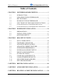
SY-P4X400 DRAGON Lite Table of Contents Table of Contents CHAPTER 1 MOTHERBOARD DESCRIPTION..............................1 1-1 1-2 1-3 1-4 1-5 1-6 1-7 INTRODUCTION.............................................................1 UNPACKING THE MOTHERBOARD ...........................1 KEY FEATURES..............................................................2 HANDLING THE MOTHERBOARD .............................6 ELECTROSTATIC DISCHARGE PRECAUTIONS........6 SY-P4X400 DRAGON Lite MOTHERBOARD LAYOUT ..........
SY-P4X400 DRAGON Lite Table of Contents APPENDIX A TROUBLE SHOOTING AT FIRST START ..............91 APPENDIX B CONTACT INFORMATION.......................................
SY-P4X400 DRAGON Lite Motherboard Description Chapter 1 MOTHERBOARD DESCRIPTION 1-1 INTRODUCTION The SY-P4X400 DRAGON Lite AGP slot/PCI Motherboard is a high-performance Socket 478 processor supported ATX form-factor system board. The SY-P4X400 DRAGON Lite uses VIA Chipset technology and supports Socket 478 class processors. This Motherboard is fully compatible with industry standards and adds many technical enhancements.
SY-P4X400 DRAGON Lite Motherboard Description One Heat Sink Compound One Back Panel Warning: Do not unpack the Motherboard from its anti-static packaging until you are ready to install it. Like most electronic equipment, your Motherboard may be damaged by electrostatic discharge. To avoid permanent damage to components ground yourself while working by using a grounding strap. Otherwise, ground yourself frequently by touching the unpainted portion of the computer chassis to drain the static charges.
SY-P4X400 DRAGON Lite Motherboard Description This ensures that the SY-P4X400 DRAGON Lite has an overwhelming overclocking potential. CPU Multiplier The SY-P4X400 DRAGON Lite supports a wide range of multipliers: 10X ~ 24X depend on CPU. MEMORY SUPPORT The SY-P4X400 DRAGON Lite supports PC1600, PC2100 and PC2700 DDR Memory module.
SY-P4X400 DRAGON Lite Motherboard Description LAN ON-BOARD Supports 10/100 Mbps base-T Ethernet. Use the Realtek RTL8100B chipset. ADVANCED FUNCTIONS The SY-P4X400 DRAGON Lite supports advanced functions such as: Wake-On-LAN Supports Wake-On-LAN (Some advanced network cards can wake the system up over the network, the WOL connector is provided by the SY-P4X400 DRAGON Lite to support this function). Multiple boot The SY-P4X400 DRAGON Lite supports booting from devices such as CD-ROM, LS-120, etc.
SY-P4X400 DRAGON Lite Motherboard Description SOYO Bonus Pack CD-ROM COMPLIANCE The SY-P4X400 DRAGON Lite complies with all important industry standards. The following underlines the reliability of the SY-P4X400 DRAGON Lite, a motherboard to trust. PC99, ACPI compliant WARRANTY All SOYO motherboards are back with one-year manufacturer’s warranty from the date of purchase. Please retain your original receipt for future warranty inquiries.
SY-P4X400 DRAGON Lite Motherboard Description 1-4 HANDLING THE MOTHERBOARD To avoid damage to your Motherboard, follow these simple rules while unpacking: Before handling the Motherboard, ground yourself by grasping an unpainted portion of the system's metal chassis. Remove the Motherboard from its anti-static packaging. Hold the Motherboard by the edges and avoid touching its components. Check the Motherboard for damage. If any chip appears loose, press carefully to seat it firmly in its socket.
SY-P4X400 DRAGON Lite Motherboard Description 1-6 SY-P4X400 DRAGON Lite MOTHERBOARD LAYOUT PS/2 KB PS/2 Mouse Connector Connector USB 1_2 LAN ATX Power PRT COM A COM B P1 AOUT J30 1 2 5 6 □ AIN P4X400 AMIC IDE 1 IDE 2 AGAME REALTEK RTL8100B AGP Slot FLP PCI#1 CDIN2 CDIN1 4 1 PCI#2 SPK5 2 10 PCI#3 9 1 JP10 WOL Header Speaker 3V Lithium Battery PCI#4 HDD LED ACPI LED PWRBT Keylock PCI#5 J25 JP5 USB20_1 5 10 1 CMOS Clear Jumper USB20_2 6 10 6 SIRCON Back Panel
SY-P4X400 DRAGON Lite Motherboard Description 1-7 SY-P4X400 DRAGON Lite MOTHERBOARD COMPONENTS AB C D E F G H Z □ I Y J AGP Slot X W V K U L T M N S R Q 8 P O
SY-P4X400 DRAGON Lite Motherboard Description A +12V Power Connector B Front panel Connectors C Chassis Cooling Fan Connector D Socket 478 Connector E VIA P4X400 North Bridge Chip F CPU Cooling Fan Connector G DIMM Banks H ATX Power Supply Connector I Bus Mastering EIDE/ATAPI Ports J Chassis Cooling Fan Connector K Floppy Disk Drive (FDD) Port L 3V Lithium Battery M Front Panel connectors N CMOS Clear Jumper O VIA VT8235 South Bridge Chip P USB 2.
SY-P4X400 DRAGON Ultra Hardware Installation Chapter 2 HARDWARE INSTALLATION Congratulations on your purchase of SY-P4X400 DRAGON Lite Motherboard. You are about to install and connect your new Motherboard. Note: Do not unpack the Motherboard from its protective anti-static packaging until you have made the following preparations. 2-1 PREPARATIONS Gather and prepare all the following hardware equipment to complete the installation successfully: 1.
SY-P4X400 DRAGON Ultra Hardware Installation 2-2 INSTALLATION GUIDE We will now begin the installation of the Motherboard. Please follow the step-by-step procedure designed to lead you to a complete and correct installation. Step 1- Install the Central Processing Unit (CPU) Step 2- Install memory modules Step 3- Install expansion cards Step 4- Connect cables, case wires, and power supply Step 5- Power on and enter BIOS setup Step 6- Install supporting software tools. See Chapter 4 for more info.
SY-P4X400 DRAGON Ultra Hardware Installation STEP 1 Install the CPU CPU Mount Procedure: To mount the Pentium® 4 Socket mPGA478 processor that you have purchased separately, follow these instructions. 1. Lift the socket handle up to a vertical position. 2. Align the blunt edge of the CPU with the matching pinhole distinctive edge on the socket.
SY-P4X400 DRAGON Ultra Hardware Installation 3. Seat the processor in the socket completely and without forcing. 4. Then close the socket handle to secure the CPU in place. Remember to connect the CPU Cooling Fan to the appropriate power connector on the Motherboard. The fan is a key component that will ensure system stability. The fan prevents overheating, therefore prolonging the life of your CPU. CPU Fan Installation Your Socket 478 processor kit comes with a cooling fan.
SY-P4X400 DRAGON Ultra Hardware Installation Step 2 Install Memory Module □ AGP Slot Your board comes with three DIMM sockets, providing support for up to 3GB of main memory using unbuffered and non-ECC DIMM modules from 64MB to 1GB. On this motherboard, DRAM speed can be set independent from the CPU front side bus speed. Depending on the DRAM clock speed setting in the BIOS setup, appropriate memory modules must be used.
SY-P4X400 DRAGON Ultra Hardware Installation Memory Configuration Table Number of Memory Modules DIMM 1 DIMM 2 DIMM 3 RAM Type DDR SDRAM (Un-buffered and Non-ECC) Memory Module Size (MB) 64/128/256/512 MB/1 GB Step 3 Install Expansion Card The motherboard has 1 AGP slot and 5 PCI slot. 1. Read the related expansion card’s instruction document before inserting the expansion card into the computer. 2. Press the expansion card firmly into expansion slot in motherboard. 3.
SY-P4X400 DRAGON Ultra Hardware Installation AGP Slot This motherboard supports AGP 4x/8x VGA CARD. When 8x VGA card is used, “AGP mode” option in the BIOS will be disabled and the “DBI Output for AGP Trans” option will appear. Note: This Motherboard supports only 1.5 volts AGP card. Using 3.3v AGP card might damage your M/B.
SY-P4X400 DRAGON Ultra Hardware Installation Step 4 Connect cables, case wires, and power supply A. IDE Device Installation (HDD, CD-ROM) □ AGP Slot IDE 1 IDE 2 Pin -1 Primary Secondary IDE IDE This Motherboard offers two primary and secondary IDE device connectors (IDE1, IDE2). It can support up to four high-speed Ultra DMA 33/ 66/100/133 HDD or CD-ROM.
SY-P4X400 DRAGON Ultra Hardware Installation B. Floppy Drive Installation Pin-1 □ AGP Slot FDC Floppy Drive connector The system supports 5 possible floppy drive types: 720 KB, 1.2 MB, 1.44 MB, 2.88 MB, and LS-120. Connect one side of the 34-pin flat cable to the floppy drive and plug the other end to the floppy drive connector on the Motherboard. This Motherboard can support up to 1 floppy drives.
SY-P4X400 DRAGON Ultra Hardware Installation + _ ACPI LED + _ □ _ Speaker HDD LED + C. Front Panel Connections AGP Slot Key Lock 1 PWRBT _ + Power LED 1 Reset Plug the computer case's front panel devices to the corresponding headers on the Motherboard. 1. Power LED & KeyLock Plug the Power LED cable into the 5-pin Keylock header. Some systems may feature a KeyLock function with a front panel switch for enabling or disabling the keyboard.
SY-P4X400 DRAGON Ultra Hardware Installation 2. Reset Plug the Reset push-button cable into the 2-pin Reset header on the Motherboard. Pushing the Reset button on the front panel will cause the system to restart the boot-up sequence. Reset Pin Assignment 1 Power Good 3. GND Speaker Attach the 4-pin PC speaker cable from the case to the Speaker header on the Motherboard. Speaker Pin Assignment _ + +5V Speaker out NC NC 4.
SY-P4X400 DRAGON Ultra Hardware Installation 5. ATX Power On/Off Switch Attach the 2-pin momentary type switch to the PWRBT header for turning On or Off your ATX power supply. PWRBT Pin Assignment 1 Power On/Off GND D. Back Panel Connections All external devices such as the PS/2 keyboard, PS/2 mouse, printer, modem, USB can be plugged directly onto the Motherboard back panel.
SY-P4X400 DRAGON Ultra Hardware Installation 1. Onboard Serial Ports COMA/COMB External peripherals that use serial transmission scheme include: - serial mouse, - and modem. Plug the serial device cables directly into the COMA/COMB 9-pin male connectors located at the rear panel of the Motherboard. 2. Parallel Port PRT This parallel port is used to connect the printer or other parallel devices.
SY-P4X400 DRAGON Ultra Hardware Installation 5. Universal Serial Bus (USB1/USB2, USB20_1/USB20_2) This Motherboard provides four USB ports for your additional devices. Plug the USB device jack into the available USB connector USB1 or USB2. - Standard device drivers come with the Win98 for commonly used USB devices. - With Win95, use the flow UHCI specifications. To use USB devices under Win95, usually you have to install the device that driver comes with the USB device you have purchased.
SY-P4X400 DRAGON Ultra Hardware Installation E. Other Connections 1. Wake-On-LAN (WOL) Attach the 3-pin connector from the LAN card which supports the Wake-On-LAN (WOL) function to the JP10 header on the Motherboard. This WOL function lets users wake up the connected computer through the LAN card.
SY-P4X400 DRAGON Ultra Hardware Installation 2. Standard Infrared (SIRCON) Plug the 10-pin infrared device cable to the SIRCON header. This will enable the infrared transfer function. This Motherboard meets both the ASKIR and HPSIR specifications.
SY-P4X400 DRAGON Ultra Hardware Installation 3. Cooling Fan Installation (1) CPU Cooling Fan (CPUFAN1, CPUFAN2) After you have seated the CPU properly on the processor, attach the 3-pin fan cable to the CPUFAN connector on the Motherboard. The fan will stop when the system enters into Suspend Mode. (Suspend mode can be enabled from the BIOS Setup Utility, [POWER MANAGEMENT] menu.
SY-P4X400 DRAGON Ultra Hardware Installation (2) Chassis Cooling Fan (CHAFAN1, CHAFAN2, CHAFAN3) Some chassis also feature a cooling fan. This Motherboard features a CHAFAN connector to provide 12V power to the chassis fan. Connect the cable from the chassis fan to the CHAFAN 3-pin connector.
SY-P4X400 DRAGON Ultra Hardware Installation 4. CD Line-in (CDIN1,CDIN2) This Motherboard provides one CD-Line in connectors. Please connect the 4-pin audio cable from your CD-ROM drive to either CDIN2.
SY-P4X400 DRAGON Ultra Hardware Installation 5. SPK5(optional) Connect one end of the Audio flat cable to SPK5 connector in the motherboard, and the other end to the small audio connector. (See unpacking the motherboard in Chapter 1 for more info on the audio flat cable) Please refer to Appendix B C-Media sound solution for more information on AUDIO function. JP1/JP2 Note: Some 5.1 speaker have different center/base assignment.
SY-P4X400 DRAGON Ultra Hardware Installation 6. MIC & LED Connector (J30) You can connect the Line-out /MIC in/LAN LED to the front panel of your PC case. (If this option is available in your PC case.
SY-P4X400 DRAGON Ultra Hardware Installation F. ATX Power Supply Use power supply specifically for P4 M/B. (ATX 12V power supply) The ATX12V power supply includes a 20-pin ATX connector that comply with the ATX specification, Version 2.03 for M/B specification, a new 4-pin receptacle/header combination--the +12V power connector--has been defined. The presence of the +12V power connector indicates that a power supply is ATX12V; the absence of the +12V power connector indicates that a supply is ATX.
SY-P4X400 DRAGON Ultra Hardware Installation Warning: Follow these precautions to preserve your Motherboard from any remnant currents when connecting to ATX power supply: Turn off the power supply and unplug the power cord of the ATX power supply before connecting to ATX PW connector. The Motherboard requires a power supply with at least 250 Watts and a "power good" signal. Make sure the ATX power supply can take at 1.
SY-P4X400 DRAGON Ultra Hardware Installation G. CMOS Clear (JP5) In some cases the CMOS memory may contain wrong data, follow the steps below to clear the CMOS memory. 1. Clear the CMOS memory by momentarily shorting pin 2-3 on jumper JP5. This jumper can be easily identified by its white colored cap. 2. Then put the jumper back to 1-2 to allow writing of new data into the CMOS memory.
SY-P4X400 DRAGON Ultra Hardware Installation Audio Upgrade The standard configuration of P4X400 DRAGON Lite motherboard supports 2 or 4-channel audio. To upgrade your DRAGON Plus on-board audio to 5.1-channel and enjoy digital sound quality, simply add a SPDIF audio connector to the motherboard. Step 5 Power On You have now completed the hardware installation of your Motherboard successfully. 1. Turn the power on 2.
SY-P4X400 DRAGON Ultra Hardware Installation Note: If you have failed to enter the BIOS, wait until the boot up sequence is completed. Then push the RESET button and press key again at the beginning of boot-up, during diagnostic checks. Repeat this operation until you get the following screen. 3.
SY-P4X400 DRAGON Ultra Hardware Installation enter the Award BIOS Setup program. The CMOS SETUP UTILITY will be shown on the screen. Then, follow these steps to configure the CPU settings. Step 1. Select [STANDARD CMOS FEATURE] Set [Date/Time] and [Floppy drive type], then set [Hard Disk Type] to “Auto”. Step 2. Select [LOAD OPTIMIZED DEFAULTS] Select the “LOAD OPTIMIZED DEFAULTS” menu and type “Y” at the prompt to load the BIOS optimal setup. Step 3.
SY-P4X400 DRAGON Lite BIOS Setup Utility Chapter 3 BIOS SETUP UTILITY This Motherboard's BIOS setup program uses the ROM PCI BIOS program from Award Software Inc. To enter the Award BIOS program's Main Menu: 1. Turn on or reboot the system. 2. After the diagnostic checks, press the [Del] key to enter the Award BIOS Setup Utility.
SY-P4X400 DRAGON Lite BIOS Setup Utility Hot Keys: Function keys give you access to a group of commands throughout the BIOS utility. Function Command Description Gives the list of options available for each General Help F1 item. Previous Restore the old values. These are the values F5 Values that the user started the current session with. Load Fail-Safe Loads all items with the most conservative F6 Defaults values. Load Optimized Loads all options with the optimize values.
SY-P4X400 DRAGON Lite BIOS Setup Utility SAVE AND EXIT SETUP Select the [SAVE & EXIT SETUP] option from the Main Menu to save data to CMOS and exit the setup utility. This option saves all your changes and causes the system to reboot. R O M C M O S A W A R D S T A N D A R D B IO S C H IP S E T P O W C M O S F E A T U R E S E R P C I/ IS A B IO S S E T U P U T IL IT Y S O F T W A R E , IN C .
SY-P4X400 DRAGON Lite BIOS Setup Utility 3-1 SOYO COMBO SETUP This Motherboard does not use any hardware jumpers to set the CPU frequency. Instead, CPU settings are software configurable with the BIOS [SOYO COMBO SETUP]. After the hardware installation is complete, turn the power switch on, then press the key during the system diagnostic checks to enter the Award BIOS Setup program. The CMOS SETUP UTILITY will display on screen.
SY-P4X400 DRAGON Lite BIOS Setup Utility System Performance System Performance Setting Description Note Normal Fast Turbo Adjust your computer performance. Default SOYO COMBO Feature Setting Description Note Frequency 100 MHz 1MHz Stepping ~ 132 MHz Press “Page Up” / “Page Down” key to Over Clock the CPU Front Side Bus in 1MHz increment or Press “Enter” key, then type the desired CPU Front Side Bus.
SY-P4X400 DRAGON Lite BIOS Setup Utility CPU Vcore Select Setting CPU Vcore Select Description Note Default This function adjust the CPU Default 1.100V, 1.125V, voltage. 1.150V, 1.175V, 1.200V, 1.225V, 1.250V, 1.275V, 1.300V, 1.325V, 1.350V, 1.375V, 1.400V, 1.425V, 1.450V, 1.475V, 1.500V, 1.525V, 1.550V, 1.575V, 1.600V, 1.625V, 1.650V, 1.675V, 1.700V, 1.725V, 1.750V, 1.775V, 1.800V, 1.825V, 1.850V AGP Voltage Adjust Setting AGP (1.5V) Voltage Select Default 1.6V 1.7V 1.
SY-P4X400 DRAGON Lite BIOS Setup Utility Onboard 6Ch H/W Audio Setting Onboard 6Ch H/W Audio Enabled Disabled Description Enabled/Disabled Onboard 6Ch H/W Audio. Note Default Onboard (10/100) LAN Setting Description Enabled Enabled/Disabled Onboard LAN. Onboard (10/100) LAN Disabled Note Default Quick Power On Self Test Setting Quick Power On Self Test Description Disabled Enabled Provides a fast POST at boot-up.
SY-P4X400 DRAGON Lite BIOS Setup Utility System Boot Control Settings Setting Description First /Second/Third Boot Device Floppy LS120 HDD-0 SCSI CDROM HDD-1 HDD-2 HDD-3 ZIP100 USB-FDD USB-ZIP USB-CDROM USB-HDD LAN Disabled Select Your Boot Device Priority Boot Other Device Disabled Enabled Select Your Boot Device Priority 44 Note Default
SY-P4X400 DRAGON Lite BIOS Setup Utility 3-1.1 Advance Turn-up Settings Caution: Change these settings only if you are already familiar with the Chipset. The [Advanced Turn-up Settings] option changes the values of the chipset registers. These registers control the system options in the computer.
SY-P4X400 DRAGON Lite BIOS Setup Utility DRAM Timing/Drive Control Setting Description Note DRAM Timing By SPD Manual If enable the DRAM will auto Default detect the DRAM timing. SDRAM CAS Latency 2.5 2 When synchronous DRAM is Default installed, the number of clock cycles of CAS latency depends on the DRAM timing. Do not reset this field from the default value specified by the system designer. Bank Interleave Disabled 2 Bank 4 Bank Increase DRAM performance.
SY-P4X400 DRAGON Lite BIOS Setup Utility 3-2 STANDARD CMOS SETUP Select the [STANDARD CMOS SETUP] option from the Main Menu and press [Enter] key. CMOS Setup Utility – Copyright ( C ) 1984-2002 Award Software Standard CMOS Features Date (mm:dd:yy) Time (hh:mm:ss) IDE Primary Master IDE Primary Slave IDE Secondary Master IDE Secondary Slave Mon, Jan 1 2002 1: 1: 8 Menu Level None None None None Change the day, month, year and century. Drive A Drive B Floppy 3 Mode Support 1.44M, 3.5 in.
SY-P4X400 DRAGON Lite BIOS Setup Utility This Main Menu function automatically detects the hard disk type and configures the [Standard CMOS Features] accordingly.
SY-P4X400 DRAGON Lite BIOS Setup Utility Hard Disks Type & Mode Choose the type and mode for the hard disks that you have already installed. Primary Setting Description Note (Secondary) Master & Slave IDE HDD Auto-Detection Press Enter To auto-detect the HDD’s size, head… on this channel IDE Primary Slave (User Type) Auto BIOS detects hard disk type Default automatically. User defines the type of hard disk.
SY-P4X400 DRAGON Lite BIOS Setup Utility Others Optional Setting Description Note Video EGA/VGA CGA 40 CGA 80 MONO (Monochrome) Select the video mode. Halt On ALL Errors No Errors All, But Keyboard All, But Diskette All, But Disk/Key When the BIOS detects system Default errors, this function will stop the system. Select which type of error will cause the system halt.
SY-P4X400 DRAGON Lite BIOS Setup Utility 3-3 ADVANCED BIOS FEATURES Select the [Advanced BIOS Features] option from the Main Menu and press [Enter] key.
SY-P4X400 DRAGON Lite BIOS Setup Utility Cache Memory Options Setting CPU L1 & L2 Cache Swap Floppy Drive Description Disabled Enabled Enables the CPU's L1 & L2 cache. Disabled Enabled Note Default Default Boot Up Floppy Seek Setting Boot Up Floppy Disabled Seek Enabled Description Note Seeks disk drives during boot up. Disabling speeds boot up. Default Boot Up NumLock Status Setting Boot Up NumLock Status On Off Description Note Puts numeric keypad in NumLock Default mode at boot-up.
SY-P4X400 DRAGON Lite BIOS Setup Utility Typematic Settings Typematic Settings Setting Typematic Rate Setting Disabled Description Note Keystrokes repeat at a rate Default determined by the keyboard. When enabled, the typematic rate and typematic delay can be selected.
SY-P4X400 DRAGON Lite BIOS Setup Utility Security Option(Continue) Setting Description Note ACPI Mode Disabled Enabled the Advanced Enabled Programmable Interrupt Controller Default (APIC) mode. MPS Version Control for OS 1.1 1.4 Allows you to choose the Multi Processor Specification (MPS) version. Default Other Control Options Setting OS Select for DRAM>64MB Description When using an OS2 operating system. Non-OS2 When using another, non-OS2 operating system. Note OS2 Default HDD S.M.A.R.T.
SY-P4X400 DRAGON Lite BIOS Setup Utility 3-4 ADVANCED CHIPSET FEATURES Select the [Advanced Chipset Features] option from the Main Menu and press [Enter] key. Caution: Change these settings only if you are already familiar with the Chipset. The [Advanced Chipset Features] option changes the values of the chipset registers. These registers control the system options in the computer.
SY-P4X400 DRAGON Lite BIOS Setup Utility 3-4.1 AGP & P2P Bridge Control Caution: Change these settings only if you are already familiar with the Chipset. The [AGP & P2P Bridge Control] option changes the values of the chipset registers. These registers control the system options in the computer.
SY-P4X400 DRAGON Lite BIOS Setup Utility AGP & P2P Bridge Control (Continue) Setting Description AGP Driving Control Auto Manual This item allows you to adjust the AGP Default driving force. Choose Manual to key in a AGP Driving Value in the next selection. This field is recommended to set in Auto for avoiding any error in your system. AGP Driving Value Min=0000 This item allows you to adjust the AGP ~ driving force.
SY-P4X400 DRAGON Lite BIOS Setup Utility 3-4.2 CPU & PCI Bus Control Caution: Change these settings only if you are already familiar with the Chipset. The [CPU & PCI Bus Control] option changes the values of the chipset registers. These registers control the system options in the computer.
SY-P4X400 DRAGON Lite BIOS Setup Utility 3-5 INTEGRATED PERIPHERALS Select the [Integrated Peripherals] option from the Main Menu and press [Enter] key. Caution: Change these settings only if you are already familiar with the Chipset. The [INTEGRATED PERIPHERALS] option changes the values of the chipset registers. These registers control the system options in the computer. The following screen shows setup default settings.
SY-P4X400 DRAGON Lite BIOS Setup Utility INTEGRATED PERIPHERALS (Continue) Setting Description OnChip USB Controller All Disabled All Enabled This should be enabled if your system has a USB Default installed on the system board and you want to use it. Even when so equipped, if you add a higher performance controller, you will need to disable this feature.
SY-P4X400 DRAGON Lite BIOS Setup Utility 3-5.1 VIA OnChip IDE Device Caution: Change these settings only if you are already familiar with the Chipset. The [VIA OnChip IDE Device] option changes the values of the chipset registers. These registers control the system options in the computer. The following screen shows setup default settings.
SY-P4X400 DRAGON Lite BIOS Setup Utility VIA OnChip IDE Device Setting Description Note On-Chip PCI IDE Primary Secondary Disabled Turn off the on-board IDE. Enabled Use the on-board IDE. Default IDE mode 0-4 0 is the slowest speed 4 is the fastest speed Auto For better performance and Default stability, we suggest you use the Auto setting to set the HDD control timing.
SY-P4X400 DRAGON Lite BIOS Setup Utility 3-5.2 SuperIO Device Caution: Change these settings only if you are already familiar with the Chipset. The [SuperIO Device] option changes the values of the chipset registers. These registers control the system options in the computer. The following screen shows setup default settings.
SY-P4X400 DRAGON Lite BIOS Setup Utility SuperIO Device Setting Onboard FDC Disabled controller Enabled Onboard Serial Port 1 / Serial Port 2 Description Note Turn off the on-board floppy controller. Use the on-board floppy controller. Default Disabled 3F8/IRQ4 Choose serial port 1 & 2's I/O address. 2F8/IRQ3 Do not set port 1 & 2 to the same address except for Disabled or 3E8/IRQ4 Auto.
SY-P4X400 DRAGON Lite BIOS Setup Utility 3-6 POWER MANAGEMENT SETUP The [POWER MANAGEMENT SETUP] sets the system's power saving functions.
SY-P4X400 DRAGON Lite BIOS Setup Utility Power Management Controls Setting ACPI Suspend S1(POS) Type S3(STR) S1 & S3 Description Note The system will enter the S1 state during suspend. (Low latency wake up) Default Power Management Option User Define Min Saving Max Saving Lets you define the system power down times.
SY-P4X400 DRAGON Lite BIOS Setup Utility Power Management Controls (Continue) Setting MODEM Use 3 IRQ 4-11, NA Description Note Assigns an IRQ# to the modem Default device. Soft-Off by PWR-BTTN Delay 4 Sec. Turns off the system power 4 seconds after pushing the power button. Instant-off Default Run VGABIOS if S3 Resume Auto Yes No PWRON After On Power Failure Off Former-Sts Press Enter IRQ/Event Activity Detect Some OS (win xp/2k) requires Default to load VGA BIOS after resume from S3.
SY-P4X400 DRAGON Lite BIOS Setup Utility IRQ/Event Activity Detect Setting Description Note PS2KB Wakeup Hot key Select Password You can boot-up your system by PS/2 K/B VIA hotkey or password. Default PS2KB Wakeup Disabled from S3/S4/S5 Ctrl+F1 ~ F12 Power Wake Any Key You can set the following hotkey : Default 1. Disable 2. Choose CTRL+F1 up to F12 3. The power key in the K/B. (if available) 4. The wake-up key in the K/B. (if available) 5. Any key in the K/B.
SY-P4X400 DRAGON Lite BIOS Setup Utility 3-6.1 IRQs Activity Monitoring This option sets the IRQs Activity Monitoring.
SY-P4X400 DRAGON Lite BIOS Setup Utility 3-7 PNP/PCI CONFIGURATIONS This option sets the Motherboard’s PCI Slots.
SY-P4X400 DRAGON Lite BIOS Setup Utility PNP/PCI Configuration Controls PNP/PCI Controls Setting Description PNP OS Installed Yes Set this field to [Yes] if you are running Windows 95, which is PnP compatible. If the OS you are running Default does not support PnP (If there is any configuration. doubt, set this field to [No]) No Reset Configuration Data Note Disabled Retain PnP configuration Default data in BIOS. Enabled Reset PnP configuration data in BIOS.
SY-P4X400 DRAGON Lite BIOS Setup Utility PNP/PCI Configuration Setup (Continue) PNP/PCI Setup Setting Description Note Interrupt Line IRQ 15 IRQ 14 How to set the BIOS to release the IRQ to the PnP Interrupt pool: PnP / PCI configuration Integrated Peripherals IRQ 15: PCI / ISA PnP On-Chip Secondary PCI IDE: disabled IRQ 14: PCI / ISA PnP On-Chip Primary PCI IDE: disabled Interrupt 12 will be released by the PnP IRQ 12 IRQ 12: PCI / ISA PnP BIOS automatically if the PS/2 Mouse Port is not used.
SY-P4X400 DRAGON Lite BIOS Setup Utility 3-8 PC HEALTH STATUS This option sets the Motherboard's PC Health Status. CMOS Setup Utility – Copyright ( C ) 1984-2002 Award Software PC Health Status Shutdown Temperature Vcore + 3.3 V + 12 V DDR Voltage AGP Voltage Disabled 1.77 V 3.24 V 12.16 V 2.48 V 1.48 V Current CPU Temp. Current CHA Temp.
SY-P4X400 DRAGON Lite BIOS Setup Utility CPU Device Monitoring (Continue) Setting Description Show the current voltage status. Vcore, +3.3V, +12V V CPU Temperature °C/°F Show the current status of CPU temperature. CHA Temperature °C/°F Show the current status of the System temperature. CPUFAN1/ CHAFAN1 Speed RPM Show the current status of CPU/CHA Fan.
SY-P4X400 DRAGON Lite BIOS Setup Utility 3-9 LOAD FAIL-SAFE DEFAULTS Select the [Load Fail-Safe Defaults] option from the Main Menu to load a pre-defined safe bios settings. This option is recommended if you have instability issue.
SY-P4X400 DRAGON Lite BIOS Setup Utility 3-10 LOAD OPTIMIZED DEFAULTS Select the [Load Optimized Defaults] option from the Main Menu to load a pre-defined optimized BIOS settings.
SY-P4X400 DRAGON Lite BIOS Setup Utility 3-11 SET SUPERVISOR PASSWORD Based on the setting you have made in the [Security Option] of the [BIOS FEATURES SETUP] section, the password prevents access to the system or the setup program by unauthorized users. Follow this procedure to set a new password or disable the password: 1. Choose [BIOS FEATURES SETUP] in the Main Menu and press [Enter]. Select the [Security Options] item and set the field to: a.
SY-P4X400 DRAGON Lite BIOS Setup Utility 3. Enter your new password and press [Enter]. The following message appears, prompting to confirm the new password: Confirm Password: 4. Re-enter your password and then press [Enter] to exit to the Main Menu. This diagram outlines the password selection procedure: Type Typethe thePassword Password and Press: Press: ROM PCI/ISA BIOS Press without ↔ Press: the password entering ↔ CMOS SETUP UTILITYWithout entering password AWARD SOFTWARE, INC.
SY-P4X400 DRAGON Lite BIOS Setup Utility BOOT MENU Boot Menu enables user to boot-up on different boot device without going into the BIOS setup. To enable boot Menu, press “ESC” after memory initialization, user will see a device menu, in which user can choose the device they wish to boot from.
SY-P4X400 DRAGON Lite Drivers Installation Chapter 4 DRIVERS INSTALLATION The SOYO-CD will Auto Run only in Windows Base Operating System. Your SY-P4X400 DRAGON Lite Motherboard comes with a CD-ROM labeled "SOYO CD." The SOYO CD contains a. The user’s manual for your new motherboard – in PDF format, b. The drivers software available for installation, and c. A database in HTML format with information on SOYO motherboards and other products. Step 1.
SY-P4X400 DRAGON Lite Drivers Installation The user's manual files included on the SOYO CD are in PDF (Postscript Document) format. In order to read a PDF file, the appropriate Acrobat Reader software must be installed in your system. Note: The Start Up program automatically detects if the Acrobat Reader utility is already present in your system, and otherwise prompts you on whether or not you want to install it. You must install the Acrobat Reader utility to be able to read the user's manual file.
SY-P4X400 DRAGON Lite Drivers Installation Step 2. Install Drivers and Utilities The following drivers need to be installed in order for the system to operate properly 1. VIA 4 in 1 driver. 2. C-Media 8738 audio driver. – Only required if you are using the onboard audio. 3. VIA USB 2.0 driver. 4. Realtek 8100b LAN driver. Should be installed manually. The rest of the available drivers are optional.
SY-P4X400 DRAGON Lite Drivers Installation Support Driver and VIA PCI IRQ Miniport Driver. For Windows NT users, the VIA IDE Bus Mastering driver is the only driver to be installed in your system. A description of 4 drivers followa: Bus Master PCI IDE Driver The ATAPI IDE driver enables the performance enhancing bus mastering functions on ATA-capable Hard Disk Drives and ensures IDE device compatibility. AGP VxD Driver VIA AGP VxD Driver is to be installed if you are using an AGP VGA device. VIAGART.
SY-P4X400 DRAGON Lite Drivers Installation possible to set alarms when current system values exceed or fall below pre-set values. VIA USB2.0 Driver for Win 98/98SE/ME/2000/XP This setup program will install the driver for VIA USB 2.0 Host Controller. Select which driver you want to install and click OK, or click Cancel to abort the driver installation and return to the main menu. Note: Once you have selected a driver, the system will automatically exit the SOYO CD to begin the driver installation program.
SY-P4X400 DRAGON Lite Drivers Installation After Windows XP installation, your device manager should look like this: 85
SY-P4X400 DRAGON Lite Drivers Installation After driver installation, your Windows XP device manager should look like this: 86
SY-P4X400 DRAGON Lite Drivers Installation 87
SY-P4X400 DRAGON Lite Drivers Installation Drivers directory list in the CD driver Audio Driver VIA 4 in 1 Hardware monitor LAN driver USB2.
SY-P4X400 DRAGON Lite Realtek Lan Driver Installation Chapter 5 Audio Driver Installation Audio Driver Installation for Windows 98/98se After you have installed the audio driver, windows may prompt you to restart your computer. When your computer restarted it may look for windows driver from your Win98CD and ask you to insert your Win98/98se CD to your CD-drive. At this point you need to insert the Win98 CD to your CD-drive and type in D:\win98 (assuming your CD-ROM in driver D).
SY-P4X400 DRAGON Lite Realtek Lan Driver Installation Chapter 6 Realtek LAN Driver Installation Install the Realtek LAN Drivers under windows NT4.0 1. Double click the Network icon in the control panel. The Network properties windows will appear. Click on the Devices tab and press the Add button. 2. Select “Unlisted or Updated Drivers” from the list of drivers in the Add window by placing the mouse pointer over it and clicking the left mouse button. Press the OK button. 3.
APPENDIX A Troubleshooting at First Start Boot-up Issues The system do not power-up, no beeping sound heard and the CPU fan does not turn on. 1. Check if the power cord is plug to the power source. 2. Check if the power is connected to the M/B. 3. Check if the cable of the case power button is connected to the M/B power button connector (see connectors and plug-ins in the manual for more info). 4. Make sure the power supply is not defective. Change the power supply. The minimum should be 250 watts.
more info on how to clear the CMOS). 2. Check all the jumper settings on the M/B. (if the M/B have any). 3. Check the memory module and the VGA card if inserted properly on the M/B. 4. If yes, change the memory module, it might be defective. Make sure the memory specification is supported by the M/B. (for more info on this, check our FAQ website). 5. Change the VGA card. Make sure the AGP card is 1.5v The system turns on for some seconds then shutdown by itself. 1.
2. Re-flash BIOS. Check on how to flash BIOS on the later part of this book. 3. Change the CMOS battery, the battery might be drained. 4. The BIOS chip might be failing. Stability Issue My system intermittently locks up, very unstable 1. Check the CPU Temp, it might be overheating. Change the CPU FAN. 2. Do not over clock your CPU 3. Check the specification of the memory module, maybe the M/B do not support it. 4. Go to BIOS setup and load fail safe settings.
2. CPU might be defective. BIOS Issue Where can I find the BIOS revision of my mainboard? It will be displayed on the up-left corner on the screen during boot-up. It will show as your board type followed by the revision number, such as kvxa_2BA1 (meaning BIOS revision 2BA1 for the SY-K7V Dragon plus! board) or 6BA+ IV_2AA2 which means SY-6BA+ IV motherboard with 2AA2 BIOS. Where can I find the latest BIOS of my motherboard? Please go to the technical support page of one of the SOYO websites (Taiwan: www.
1. Make sure that you have installed the VIA 4 in 1 driver. 2. Install/ re-install the VGA driver. After wake-up from Suspend to RAM or Standby mode, the screen has no display but I can hear the hard disk operating 1. Install VIA 4 in 1 driver. 2. Check the VGA card manufacturer for driver update, or make sure the VGA card support Suspend to Ram function. Audio Issue How can I disable the on-board Audio? Go to the SOYO Combo Feature in the BIOS setup, then set the “onboard 6CH H/W audio” to disable.
This is because the 3-wire audio cable from the CD-ROM to the on-board CDIN1 connector in the M/B is not connected. See manual for location of CDIN1. The sound from my sound card is distorted when Windows start. What is wrong? If you are using an ISA sound card, please make sure the IRQ needed for the sound card is set to 'Legacy ISA' in the BIOS. In other word, if your ISA sound card takes IRQ5, then set IRQ5 to 'Legacy ISA'.
LAN Issues During LAN driver installation, the system hangs on 75%, why? Enable the onboard LAN in the BIOS setup. For updated FAQs, please check http://www.soyo.com.tw/faq.htm or http://www.soyousa.com/faqs.
APPENDIX B How to contact us: If you are interested in our products, please contact the SOYO sales department in the region you live. If you require Technical Assistance, please contact our Technical Support in the region you live. SOYO prefers Email as communication medium, remember to always add to the email the country that you live in. TAIWAN SOYO COMPUTER INC. No. 21 Wu-Kung 5 Rd., Hsing Chuang City, Taipei Hsien, Taiwan, R.O.C. TEL: 886-2-22903300 FAX: 886-2-22983322 http://www.soyo.