2001 VIDERE DESIGN STH-DCAM USER’S MANUAL STH-DCAM Stereo Head User’s Manual Updated – Rev 2 2001 Videre Design 1
2001 VIDERE DESIGN STH-DCAM USER’S MANUAL 9 Table of Contents 1 Introduction ...........................................................................................3 2 Quick Start.............................................................................................4 3 Hardware Overview...............................................................................5 3.1 Hardware Schematic......................................................................5 3.2 Color and Monochrome.......
2001 VIDERE DESIGN STH-DCAM USER’S MANUAL 1 Introduction The STH-DCAM (Dual-DCAM) is a compact, low-power digital stereo head with an IEEE 1394 digital interface. It consists of two VGA (640x480), progressive scan CCD imagers and associated IEEE 1394 electronics, mounted in a rigid, milled Delrin frame. The CCD imagers are Sony HAD ¼” devices, with square pixels and progressive scan output. They have 648 H by 484 V pixels, and are colorized using a standard Bayer pattern.
2001 VIDERE DESIGN STH-DCAM USER’S MANUAL 2 Quick Start The STH-DCAM comes assembled, with 3.6 mm lenses as standard. To set up and test the STH-DCAM, you will need the following: 1. Host computer with a 1394 PCI or PCMCIA card, OHCI compliant. 2. 1394 6-pin cable. 3. Capture software or Small Vision System installed on the host computer. Install the 1394 host card, if necessary, according to the directions in Section 7.1.
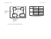
2001 VIDERE DESIGN STH-DCAM USER’S MANUAL 3.1 Figure 3-2 shows the design of the internal hardware of the STH-DCAM. In the stereo imager module, two Sony CCD imagers, each of size 648x486 pixels, digitize incoming light into a digital stream. A full frame is captured at once, and then read out line by line. The imagers operate in progressive mode only, that is, each line is output in succession from the full frame. 3 Hardware Overview Figure 3-1 shows the hardware configuration of the STH-DCAM.
2001 VIDERE DESIGN STH-DCAM USER’S MANUAL Sync signals Left Imager STH-DCAM Digital Stereo Head 1394 imaging commands Right Imager 8-bit pixels 12 MHz per imager 1394 Interface Electronics 1394 commands Frame Size Frame rate, monochrome Frame rate, color 640x480 30 Hz 30 Hz 15 Hz 15 Hz 7.5 Hz 7.5 Hz 30 Hz 30 Hz 15 Hz 15 Hz 7.5 Hz 7.5 Hz 320x240 1394 Interface Electronics Table 3-1 Supported frame rates for the STHDCAM, 400 Mbps IEEE 1394 bus.
2001 VIDERE DESIGN STH-DCAM USER’S MANUAL small amount of methyl alcohol or similar lens-cleaning solvent, and wipe the imager glass surface gently. Dry with a similar tissue. 4 Lenses 4.3 The STH-DCAM uses standard miniature lenses (12 x 0.5 mm). Goodquality, fixed-focus lenses with low distortion and high light-gathering capability are best. The imager size is the largest size of imager that can be covered by the lens. For the STH-DCAM, the lens must be 1/4” or larger.
2001 VIDERE DESIGN STH-DCAM USER’S MANUAL where b is the baseline between the imagers, f is the focal length of the lens, and ∆d is the smallest disparity the stereo system can detect. For the STHDCAM, b is 90 mm, and ∆d is 0.35 um (pixel size of 5.6 um, divided by the interpolation factor of 16). Figure 4-1 plots this relationship for several focal lengths. At any distance, the range resolution is inversely proportional to the focal length. 4.
2001 VIDERE DESIGN STH-DCAM USER’S MANUAL PCI cards have 6-pin ports, and supply power. PCMCIA cards do not have the capability of supplying power, and power can be supplied through the power jack. In some cases, the PCMCIA card has an input for external power. Plug the STH-DCAM cables into a port, and supply power through the external input. 5 1394 Interface Digital image information is transferred from the STH-DCAM to the host PC via an IEEE 1394 cable.
2001 VIDERE DESIGN STH-DCAM USER’S MANUAL monochrome channels and one RGB color channel. The color channel corresponds to the left image, which is the reference image for stereo. The color image can be de-warped, just like the monochrome image, to take into account lens distortion (see the Small Vision System User’s Manual). 6 User Controls The CCD imagers are fully controllable via the IEEE 1394 interface.
2001 VIDERE DESIGN STH-DCAM USER’S MANUAL Both imagers are treated in exactly the same manner. It is not possible to set a different exposure or gain on each imager. Digitization control can operate in either manual or automatic mode. Refer to Figure 6-1 for the controls in the video capture program. In manual mode, the user program sets the exposure and gain. The exposure and gain are based on a 0 to 100 scale. Here are some tips for setting exposure and gain. 6.
2001 VIDERE DESIGN STH-DCAM USER’S MANUAL 7.2.1 MS Windows Installation 7 Installing the 1394 Host Card and Capture Software To install the software under MS Windows, execute the file svscap22X.exe. The installation process will add the relevant interface and application software. The STH-DCAM connects to a host computer via a digital 1394 interface. The host PC must have a 1394 port, and software to interface to the video stream from the camera.
2001 VIDERE DESIGN STH-DCAM USER’S MANUAL 7.2.2 Linux Installation To install the software under Linux, untar the file svscap22X.tgz in a new directory, which will become the top-level directory of the software. Add bin/ to your LD_LIBRARY_PATH variable. The directory structure for the software is: bin/ smallvcap stcap libsvscap.so pixcap.so dcamcap.so src/ svs.h svsclass.h samples/ *.cpp makefile There are two applications.
2001 VIDERE DESIGN STH-DCAM USER’S MANUAL 8 Interface Software API Please see the Small Vision System User’s Manual for information about the software API for capturing and saving images.
2001 VIDERE DESIGN STH-DCAM USER’S MANUAL Color, 8 bits / pixel, Bayer pattern 9 Technical Specifications Scan mode Progressive 9.1 Pixel size 5.6 um square Geometry Housing Rigid milled Delrin frame Sensitivity 1 lux 9 cm, fixed Exposure Electronic, 292 us to frame time Baseline Imager size 1/4 inch diagonal Gain Lens type 12 mm miniature, interchangeable Resolution 640 H x 480 V 9.2 18 dB Interface 9.
2001 VIDERE DESIGN STH-DCAM USER’S MANUAL Stereo module size 6" x 2.
2001 VIDERE DESIGN STH-DCAM USER’S MANUAL 10 Technical Support For technical support, please contact Videre Design by email or FAX. Videre Design P.O. Box 585 Menlo Park, CA 94026-0585 Fax: (650)323-3646 Email: mclaughl@dnai.com Technical information about stereo algorithms and stereo calibration can be found at www.ai.sri.com/~konolige/svs.