
Motherboard Quick Start Guide

SY-5EHM/5EH5 V1.x
Quick Start Guide
13
Installation
Step 5. Attach Connectors
This section tells how to connect internal peripherals and power supply to the
Motherboard.
Internal peripherals include IDE devices (HDD, CD-ROM), Floppy Disk Drive, Front Panel
Devices (Turbo LED, Internal Speaker, Reset Button, IDE LED, and KeyLock Switch.),
Wake-On-LAN card, VGA card, Sound Card, and other devices.
For more details on how to connect internal and external peripherals to your new
5EHM/5EH5 V1.x Super 7™ Motherboard, please refer to 5EHM/5EH5 V1.x
Motherboard User's Guide and Technical Reference online manual on CD-ROM.
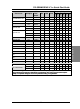
Connectors and Plug-ins
IrDA (Infrared Device Header): IR1 Wake-On-LAN Header: JP44
Pin1 Pin2 Pin3 Pin4 Pin5 Pin1 Pin2 Pin3
VCC None IRRX GND IRTX 5VSB GND MP-Wakeup
CPU Cooling Fan: JP12
USB
Pin1 Pin2 Pin3
GND 12V NC
Connect your USB devices to this header.
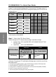
Power LED Keylock
Pin1 Pin2 Pin3
Pin1 Pin2
5V NC GND
Control Pin GND
Speaker
Pin1 Pin2 Pin3 Pin4
5V NC NC Speaker out
HDD LED
TB LED
PWRBT RESET
Pin1 Pin2 Pin1 Pin2 Pin1 Pin2 Pin1 Pin2
LED Anode
LED
Cathode
LED Anode
LED
Cathode
Power
On/Off
GND
Power
Good
GND
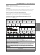
ATX Power On/Off: PWRBT
Connect your power switch to this header (momentary switch type).
To turn off the system, please press this switch and hold down for longer than 4 seconds.
ATX Power Supply: ATX PW
Attach the ATX Power cable to this connector.
Please make sure the ATX power supply can take at least 720mA load on the 5V standby lead (5VSB), if
you want to use the advanced power management functions like Power-On by modem or WOL.
Note: Use only ONE type of power supply. If an AT power supply is used, do not attach an ATX
power supply.
AT Power Cable
Connect the AT Power cable to this connector. If you use AT power supply.
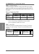
Power LED
Key Lock
Speaker
Reset
PWRBT
Turbo LED
HDD LED
+
+
++
_ _
_
_