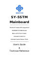
SY-5STM Mainboard ************************************************ Pentium ® Class CPU supported SiS5598 PCI Mainboard Micro-ATX Form Factor Onboard VGA Port Onboard Audio-Stereo Ports ************************************************ User's Guide & Technical Reference
SOYO ™ SY-5STM About This Guide This User's Guide is for assisting system manufacturers and end users in setting up and installing the mainboard. Information in this guide has been carefully checked for reliability; however, no guarantee is given as to the correctness of the contents. The information in this document is subject to change without notice. Copyright Notice Copyright 1998, Soyo Computer Inc. All rights reserved. This manual is copyrighted by Soyo Computer Inc.
Table of Contents SY-5STM Table of Contents SY-5STM MAINBOARD LAYOUT........................................................ 1 KEY FEATURES................................................................................... 1 MAINBOARD FEATURES.................................................................... 2 QUICK INSTALLATION GUIDE ........................................................... 5 CHAPTER 1 INTRODUCTION......................................................... 27 1-1 KEY FEATURES ........
Table of Contents 3-7 SY-5STM LOAD BIOS DEFAULTS .............................................. 60 3-8 INTEGRATED PERIPHERALS .................................... 61 3-9 SUPERVISOR PASSWORD ........................................ 66 3-10 USER PASSWORD...................................................... 67 3-11 IDE HDD AUTO DETECTION ...................................... 68 CHAPTER 4 ONBOARD VGA AND AUDIO.................................... 69 4-1 ONBOARD VGA..................................
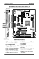
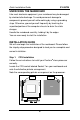
Mainboard Layout SY-5STM SY-5STM MAINBOARD LAYOUT PS/2 KB PS/2 Mouse Connector Connector CPUFAN DIMM 2 DIMM 1 USB 1 1 4 2 3 1 JP17 USB 2 JP30 PRT FDC JP22 2 4 6 8 10 1 COM 2 COM 1 1 2 3 1 3 5 7 9 JP10 JP11 JP12 JP13 JP14 JP15 JP16 JP44 VGA 1 3 1 2 3 WOL Header 1 ATX Power JOYSTICK LINE-OUT 1 SiS 5598 Chipset SMC® FDC37C669Q LINE-IN MIC JACK PCI Slot #1 IDE 2 IDE 1 JP5 SIR PCI Slot #2 1 1 J2 ALS120 Flash BIOS 3V Lithium Battery 3 _ _ Speaker _ + ISA Slot #1 JP2
Mainboard Features SY-5STM MAINBOARD FEATURES Board Size Socket 7 4-layer PCB, 19x24.
Mainboard Features SY-5STM HDD_LED PWRBT J2 J4, J5 JP1, JP2 JP5 2-pin IDE Device LED Connector ATX Power On/Off Switch 2-pin Connector Microphone Mono/Stereo Jumper Enable/Disable Onboard Sound Function Jumpers 2 x CD Line-in 4-pin Connectors CMOS Clear Jumper JP10~JP13 JP14~JP16 JP17 JP22 JP30 JP44 CPU Host Bus Frequency Jumpers CPU Frequency Multiplier Jumpers CPU Single/Dual Voltage Type Jumper CPU Burst Mode Jumper CPU Voltage Selection Jumper WOL (Wake-On-LAN) 3-pin Connector BACK-PANEL FEATURES
Mainboard Features SY-5STM KEY FEATURES VGA onboard supports Unified Memory Architecture (UMA) 3D PnP Audio onboard Supports CPU voltage from 2.0V to 3.5V in 0.
Quick Installation Guide SY-5STM QUICK INSTALLATION GUIDE Congratulations on your purchase of SY-5STM Mainboard. You are about to install and connect your new mainboard. Note: Do not unpack the mainboard from its protective anti-static packaging until you have made the following preparations. PREPARATIONS Gather and prepare all the following hardware equipment to complete the installation successfully: 1. Pentium processor with CPU cooling fan. 2. DIMM memory module 3.
Quick Installation Guide SY-5STM UNPACKING THE MAINBOARD Like most electronic equipment, your mainboard may be damaged by electrostatic discharge. To avoid permanent damage to components ground yourself while working by using a grounding strap. Otherwise, ground yourself frequently by touching the unpainted portion of the computer chassis to drain the static charges. Handle the mainboard carefully, holding it by the edges. You are now ready to start the installation.
Quick Installation Guide SY-5STM Follow these steps to install the CPU in the Socket 7: 1. Lift the socket handle up to a vertical position. 2. Align the blunt edge of the CPU with the matching pinhole distinctive edge on the socket. 3. Seat the processor in the socket completely and without forcing. 4. Then close the socket handle to secure the CPU in place. 1 2 3 Step 2. 4 CPU Fan Installation Your Pentium ® processor kit comes with a cooling fan.
Quick Installation Guide Step 3. SY-5STM CPU Voltage Setting (JP17, JP30) 4 JP17 3 2 1 Voltage Type: (Single/Dual) (*Default: Single) 2 4 6 810 CPU Voltage (*Default: 3.52V) JP30 1 3 5 7 9 Default CPU voltage settings are as follows: Ø J17: Single* Voltage (*Default) Ø JP30: 3.52* V (*Default) If the markings on your CPU correspond to the default values, you do not need to set any voltage jumper since your mainboard comes pre-configured with the default values. Please go on to Step 4.
Quick Installation Guide SY-5STM Voltage Settings for Various Processors Processor Type Vcore Voltage Voltage Value: Voltage Setting Type: JP17 JP30 Intel P54C - P90 Intel P54C - P100 Intel P54C - P120 Intel P54C - P133 Intel P54C - P150 Intel P54C - P166 Intel P54C - P180 Intel P54C - P200 Intel P55C - P180 Intel P55C - P200 Intel P55C - P233 AMD K5 - PR90 AMD K5 - PR100 AMD K5 - PR120 AMD K5 - PR133 AMD K5 - PR150 AMD K5 - PR166 AMD K6 - 166 AMD K6 - 200 2 4 6 810 JP17 Single 3.
Quick Installation Guide SY-5STM Voltage Settings for Various Processors (continued) Processor Type Vcore Voltage Voltage Value: Voltage Setting Type: JP17 JP30 2 4 6 810 JP17 Cyrix 6x86 - PR200+ Dual 2.8V 4 3 2 1 JP30 1 3 5 7 9 Cyrix MX - PR166** Cyrix MX - PR200** Cyrix MX - PR233** Cyrix MX - PR266** Cyrix M II - 300** IDT WinChip C6-180 IDT WinChip C6-200 IDT WinChip C6-225 IDT WinChip C6-240 2 4 6 810 JP17 Dual 2.9V 4 3 2 1 JP30 1 3 5 7 9 2 4 6 810 JP17 Single 3.
Quick Installation Guide Step 4. SY-5STM CPU Frequency Setting (JP10~16) 1 JP10 JP11 JP12 JP13 JP14 JP15 JP16 2 3 Host Bus Frequency (*Default: 66MHz) Frequency Multiplier (*Default: 2.0x) The SY-5STM mainboard is designed to support most Pentium® class processors currently on the market. Jumpers JP10~16 are used to configure the mainboard frequency parameters to match the working frequency of your CPU.
Quick Installation Guide SY-5STM Please refer to the following table that gives you the correct frequency settings for the specific brand and model of CPU you are installing on this mainboard. Frequency Settings for Intel® Processors Processor Ratio Bus Multiplier CPU Host Bus Frequency Setting Clock JP14~16 ClockJP10~13 Intel P54C - P90 1.5 x 60MHz JP14 JP15 JP16 JP10 JP11 JP12 JP13 Intel P54C - P100 1.5 x 66MHz JP14 JP15 JP16 JP10 JP11 JP12 JP13 Intel P54C - P120 2.
Quick Installation Guide SY-5STM Frequency Settings for AMD ™ Processors Processor Ratio Bus Multiplier CPU Host Bus Frequency Setting Clock JP14~16 ClockJP10~13 AMD K5 - PR90 1.5 x 60MHz JP14 JP15 JP16 JP10 JP11 JP12 JP13 AMD K5 - PR100 1.5 x 66MHz JP14 JP15 JP16 JP10 JP11 JP12 JP13 AMD K5 - PR120 2.0 x 60MHz JP14 JP15 JP16 JP10 JP11 JP12 JP13 AMD K5 - PR133 2.0 x 66MHz JP14 JP15 JP16 JP10 JP11 JP12 JP13 AMD K5 - PR150 2.5 x 60MHz JP14 JP15 JP16 JP10 JP11 JP12 JP13 AMD K5 - PR166 2.
Quick Installation Guide SY-5STM Frequency Settings for Cyrix ™ Processors Processor Ratio Bus Multiplier CPU Host Bus Frequency Setting Clock JP14~16 ClockJP10~13 Cyrix 6x86 - PR150+ Cyrix 6x86 - PR166+ Cyrix 6x86 - PR200+ 2.0 x 60MHz 2.0 x 66MHz 2.5 x 66MHz JP14 JP15 JP16 JP10 JP11 JP12 JP13 JP14 JP15 JP16 JP10 JP11 JP12 JP13 JP14 JP15 JP16 JP10 JP11 JP12 JP13 Cyrix MX - PR166** 2.5 x 60MHz JP14 JP15 JP16 JP10 JP11 JP12 JP13 Cyrix MX - PR166** 2.
Quick Installation Guide SY-5STM Frequency Settings for IDT ™ Processors Processor Ratio Bus Multiplier CPU Host Bus Frequency Setting Clock JP14~16 ClockJP10~13 IDT WinChip C6-180 3.0 x 60MHz JP14 JP15 JP16 JP10 JP11 JP12 JP13 IDT WinChip C6-200 3.0 x 66MHz JP14 JP15 JP16 JP10 JP11 JP12 JP13 JP14 JP15 JP16 JP10 JP11 JP12 JP13 JP14 JP15 JP16 JP10 JP11 JP12 JP13 IDT WinChip C6-225 IDT WinChip C6-240 3.0 x 75MHz 4.
Quick Installation Guide SY-5STM Step 5. DRAM Module Installation This mainboard supports two DIMM banks from 8 to 128 MB with no other restrictions on memory configurations. You can install the memory in any combination without having to rely on a memory configuration table. Memory configuration is therefore "table-free" in any memory bank. DIMM 2 DIMM 1 This mainboard supports both EDO and SDRAM types of memory modules.
Quick Installation Guide SY-5STM Step 6. IDE Device Installation (HDD, CD-ROM) This mainboard offers two primary and secondary IDE device connectors (IDE1, IDE2.) It can support up to four high-speed HDD or CD-ROM. Connect one side of the 40-pin flat cable to the IDE device (HDD or CD-ROM) and plug the other end to the primary (IDE1) or secondary (IDE2) directionally keyed IDE connector on the mainboard. This mainboard can support up to four HDDs. Step 7.
Quick Installation Guide SY-5STM Plug the computer case's front panel devices to the corresponding connectors on the mainboard. 1. Power LED & KeyLock Plug the Power LED cable into the 5-pin Keylock connector. Some systems may feature a KeyLock function with a front panel switch for enabling or disabling the keyboard. Connect the KeyLock switch to the 5-pin Keylock connector on the mainboard. Please install according to the following pin assignment: pin 1,3 are for Power LED and pin 4,5 are for Keylock.
Quick Installation Guide SY-5STM 6. ATX Power On/Off Switch Attach the 2-pin momentary type switch to the PWRBT connector for turning On or Off your ATX power supply. Step 9. Back Panel Connections All external devices such as the keyboard, printer, PS/2 mouse, modem, USB, VGA monitor, joystick, audio-stereo line-in and lineout, and a microphone, can be plugged directly onto the mainboard back panel.
Quick Installation Guide SY-5STM 1. Onboard Serial Port COM1 External peripherals that use serial transmission scheme include: - serial mouse, - and modem. Plug the serial device cables directly into the COM1 9-pin male connector located at the rear panel of the mainboard. 2. Parallel Port PRT This parallel port is used to connect the printer or other parallel devices. Plug the parallel device cable into the 26-pin female connector located at the rear panel of the mainboard. 3.
Quick Installation Guide SY-5STM Step 10. Other Connections 1. Serial Port COM 2 In addition to the onboard serial connector COM1 located at the rear panel, your mainboard comes with a second serial port COM2 equipped with a flat cable and external connector. The mainboard package includes one 9-pin male external serial connector with 9-pin flat cable.
Quick Installation Guide SY-5STM 2. Wake-On-LAN (WOL) Attach the 3-pin connector from the LAN card which supports the Wake-On-LAN (WOL) function to the JP44 connector on the mainboard. This WOL function lets users wake up the connected computer through the LAN card. Please install according to the following pin assignment: Wake-On-LAN JP44 Pin Assignment GND 5V SENSOR 1 2 3 3. Infrared (IR) Plug the 5-pin infrared device cable to the IR connector. This will enable the infrared transfer function.
Quick Installation Guide SY-5STM 4. Other Display Cards Insert other types of VGA cards into the PCI or ISA expansion slots according to card specifications. Notice: If you install another PCI VGA card, the onboard VGA port will automatically be disabled. Step 11. CPU Cooling Fan Installation After you have seated the CPU cooling fan properly on the processor, attach the 3-pin fan cable to the CPUFAN connector on the mainboard.
Quick Installation Guide SY-5STM Step 12. ATX Power Supply Plug the connector from the power directly into the 20-pin male ATX PW connector on the mainboard, as shown in the following figure. ATX Power Warning: Follow these precautions to preserve your mainboard from any remnant currents when connecting to ATX power supply: Turn off the power supply and unplug the power cord of the ATX power supply before connecting to ATX PW connector.
Quick Installation Guide SY-5STM Please install the ATX power according to the following pin assignment: ATX Power 12V 5VSB PW-0K 5V 5V -5V Ø Pay special care to the directionality. GND 5V GND 5V GND GND GND PS-ON Ø Make sure pin 1 is in its position. GND 3.3V 3.3V GND -12V 3.3V Step 13. CMOS Clearing (JP5) After you have turned off your computer, clear the CMOS memory by momentarily shorting pins 2-3 on jumper JP5, for a few seconds.
Quick Installation Guide SY-5STM 3. The BIOS Setup screen appears: ROM PCI/ISA BIOS CMOS SETUP UTILITY AWARD SOFTWARE, INC.
Introduction SY-5STM Chapter 1 INTRODUCTION The SY-5STM PCI mainboard is a high-performance Micro-ATX form-factor system board. SY-5STM uses the SiS5598 PCI Chipset technology and supports Pentium ® class processors. This mainboard is fully compatible with industry standards and adds many technical enhancements.
Introduction SY-5STM l BUS Controller Ø Compliant with v2.
Introduction SY-5STM 1-2 UNPACKING THE MAINBOARD When unpacking the mainboard, check for the following items: Ø Ø Ø Ø Ø Ø The SY-5STM SiS 5598 PCI Mainboard This Quick Start Guide * The Installation CD-ROM * One IDE Device Flat Cable One Floppy Disk Drive Flat Cable One 9-pin External Serial Connector with 9-pin Flat Cable * If your board comes with a driver disc and a paper manual, the Quick Start Guide and the CD-ROM are not included in the package.
Introduction SY-5STM 1-4 ELECTROSTATIC DISCHARGE PRECAUTIONS Make sure to ground yourself before handling the mainboard or other system components. Electrostatic discharge can easily damage the components. Note that you must take special precautions when handling the mainboard in dry or air-conditioned environment. To protect your equipment from electrostatic discharge, take the following precautions: Ø Do not remove the anti-static packaging until you are ready to install.
Hardware Setup SY-5STM Chapter 2 HARDWARE SETUP In addition to the Installation Guide, this section is designed to help you configure the mainboard hardware and to provide complementary knowledge of the hardware. (This chapter is designed for Normal edition mainboard use only.) Warning: Turn off the power to the mainboard, system chassis, and peripheral devices before performing any work on the mainboard or system. After you install the mainboard: 1. Set the Voltage Type jumper JP17 2.
Hardware Setup SY-5STM 2-1 CPU VOLTAGE SETTING (JP17, JP30) JP17 and JP30 are the only jumpers that you need to set for your CPU voltage on this mainboard. There are two kinds of CPU voltages currently on the market depending on the CPU manufacturer: Ø Single Voltage (CPU: P54C, AMD-K5, Cyrix 6x86, IDT Ø WinChip C6) Dual Voltage (CPU: P55C, AMD-K6, AMD-K6-2 Cyrix 6x86L,Cyrix 6x86MX, Cyrix M II) Those processors may come in various voltages on different markets.
Hardware Setup SY-5STM 2-2 CPU FREQUENCY SETTING (JP10~16) Configure the JP10~16 jumpers to the settings that match your CPU speed. Refer to the following tables to set the Frequency Multiplier and Host Bus Frequency of your CPU: Frequency Multiplier Host Bus Frequency Multiplier JP14 JP15 JP16 1.5x 2.0x* 2.5x 3.0x 3.5x 4.0x 4.
Hardware Setup SY-5STM 2-3 CPU BURST MODE JUMPER (JP22) There are two types of CPU burst modes according to manufacturer design: Ø Interleave Burst (CPU: Intel P54C/P55C, AMD K5/K6/K6-2, IDT WinChip C6) Ø Linear Burst (CPU: Cyrix 6x86/L/MX, Cyrix M II) You do not need to adjust JP22 if you are using an Intel® P54C/P55C, an AMD ™K5/K6/K6-2, or a IDT C6 ™series CPU. The default setting on JP22 is Interleave Burst Mode.
Hardware Setup SY-5STM 2-4 SOUND SETTINGS (J4, J5, J2) The onboard audio features of your mainboard are controlled by jumpers J4, J5, J2. Choose the available sound options among the following table: Sound Settings J4 J5 J2 Onboard Sound: Enable * open* open* Onboard Sound: Disable short short Microphone: Stereo * short* Microphone: Mono open * Starred items refer to default settings.
Hardware Setup SY-5STM 2-7 CACHE CONFIGURATION This mainboard has a write-back caching scheme with a built-in 512KB Level 2 Pipelined Burst cache onboard to improve the system performance. The cache size and RAM locations are specified as follows: Cache Size Cache RAM TAG RAM 512 KB 64K x 64 on U20 16K x 8 on U21 Cacheable Range 128 MB 2-8 MEMORY CONFIGURATION This mainboard features 2 x DIMM Banks for 168-pin 3.
Hardware Setup SY-5STM 2-9 MULTI I/O ADDRESSES Default settings for multi-I/O addresses are as follows: Port I/O Address IRQ Status LPT1 378H 7 ECP + EPP COM1 3F8H 4 COM2 2F8H 3 Warning: If a default I/O address conflicts with other I/O cards such as sound card, you must change one of the I/O addresses to remedy to this address conflict.
BIOS Setup Utility SY-5STM Chapter 3 BIOS SETUP UTILITY This mainboard's BIOS setup program uses the ROM PCI/ISA BIOS program from Award Software Inc. To enter the Award BIOS program's Main Menu: 1. Turn on or reboot the system. 2. After the diagnostic checks, press the [Del] key to enter the Award BIOS Setup Utility. ROM PCI/ISA BIOS CMOS SETUP UTILITY AWARD SOFTWARE, INC.
BIOS Setup Utility SY-5STM Hot Keys: Function keys give you access to a group of commands throughout the BIOS utility. Function F1 Shift F2 F5 Command Description Help Gives the list of options available for each item. Color Change the color of the display window. Old values Restore the old values. These are the values that the user started the current session with. Loads all options with the BIOS Setup default values. Loads all options with the Power-On default values.
BIOS Setup Utility SY-5STM 3-1 STANDARD CMOS SETUP Select the [STANDARD CMOS SETUP] option from the Main Menu and press [Enter] key. ROM PCI/ISA BIOS STANDARD CMOS SETUP AWARD SOFTWARE, INC. Date (mm:dd:yy) : Fri, May 29 1998 Time (hh:mm:ss) : 9 : 42 : 43 HARD DISKS Primary Master Primary Slave Secondary Master Secondary Slave PRECOMP LANDZ SECTOR MODE : AUTO : None : None TYPE SIZE 0 0 0 CYLS HEAD 0 0 0 0 0 0 0 0 0 0 0 0 0 0 0 AUTO ------- : None 0 0 0 0 0 0 ---- Drive A : 1.
BIOS Setup Utility SY-5STM 3-1.2 Hard Disks Type & Mode Choose the type and mode for the hard disks that you have already installed. Primary Setting Description Note (Secondary) Master & Slave Type Auto 1-47 User Mode BIOS detects hard disk type Default automatically. Selects standard hard disk type. User defines the type of hard disk. Auto BIOS detects hard disk mode Default automatically.
BIOS Setup Utility SY-5STM 3-1.4 Video Select the video mode: EGA/VGA (Default), CGA 40, CGA 80, Mono (Monochrome). 3-1.5 Halt On When the BIOS detects system errors, this function will stop the system. Select which type of error will cause the system halt: All Errors (Default), No Errors, All But Diskette, All But Keyboard, All But Disk/Key.
BIOS Setup Utility SY-5STM 3-2 BIOS FEATURES SETUP Select the [BIOS FEATURES SETUP] option from the Main Menu and press [Enter] key. ROM PCI/ISA BIOS BIOS FEATURES SETUP AWARD SOFTWARE, INC.
BIOS Setup Utility SY-5STM 3-2.1 Virus Warning Setting Virus Warning Disabled Enabled Description Enable this option to protect the boot sectors and partition tables of your hard disk. Any attempt to write to them will the system to halt and display a warning message. 3-2.2 Cache Memory Options Setting Description CPU Internal Cache Disabled Enabled Enables the CPU's internal cache. External Cache Note Default Disabled Enabled Enables the external memory.
BIOS Setup Utility SY-5STM 3-2.3 System Boot Control Settings System Boot Setting Description Control Settings Quick Power On Disabled Self Test Enabled Provides a fast POTS at Default boot-up.
BIOS Setup Utility SY-5STM System Boot Control Settings (continued) System Boot Setting Description Control Settings Gate A20 Option Normal Fast Memory Parity Check Enabled Note Allows RAM access Default above 1MB using the fast gate A20 line. This allows to perform a Default redundancy check on the parity bit in the data strings. This method is used for error detection when the parity is not found. Disabled 3-2.
BIOS Setup Utility SY-5STM 3-2.5 Security Option Use this feature to prevent unauthorized system boot-up or use of BIOS Setup. The following table describes the security settings. Setting Description Security Option System Each time the system is booted, the password prompt appears. Setup If a password is set, the password prompt only appears when you attempt to enter the BIOS Setup program. 3-2.
BIOS Setup Utility SY-5STM 3-3 CHIPSET FEATURES SETUP Caution: Change these settings only if you are already familiar with the Chipset. The [CHIPSET FEATURES SETUP] option changes the values of the chipset registers. These registers control the system options in the computer. ROM PCI/ISA BIOS CHIPSET FEATURES SETUP AWARD SOFTWARE, INC.
BIOS Setup Utility SY-5STM CHIPSET FEATURES SETUP CHIPSET Setting Description FEATURES Auto Configuration L2 (WB) Tag Bit Length Disabled Enabled 7bits 8bits Note It is strongly recommended Default to enable this option so that the system automatically sets all chipset feature options on the left panel of the screen (except for cache update & BIOS cacheable).
BIOS Setup Utility SY-5STM CHIPSET FEATURES SETUP (Continued) CHIPSET Setting Description FEATURES Note CAS# Pulse Width (FP) 2T 1T Use the default setting Default CAS# Pulse Width (EDO) 1T 2T Use the default setting Default RAMW# Assertion Timing 3T 2T Use the default setting Default CAS Precharge Time (FP) 1T/2T 2T,1T Use the default setting Default CAS Precharge Time (EDO) 1T/2T 2T,1T Use the default setting Default X-2-2-2 Use the default setting X-1-1-1 Default SDRAM WR Retire
BIOS Setup Utility SY-5STM CHIPSET FEATURES SETUP (Continued) CHIPSET Setting Description FEATURES Note ISA Bus Clock Frequency PCILK/4 System BIOS Cacheable Disabled Enabled Video BIOS Cacheable Disabled Enabled Memory Hole At 15M-16M Disabled Enabled VGA Shared Memory Size 1 MB VGA memory size shared 0.5-4 MB with system memory. VGA Memory Clock (MHz) 40 Selects the frequency of the Default 40-70 MHz VGA memory clock. The ISA bus runs on PCI Default Bus Clock divided by 4.
BIOS Setup Utility SY-5STM 3-4 POWER MANAGEMENT SETUP The [POWER MANAGEMENT SETUP] sets the system's power saving functions. ROM PCI/ISA BIOS POWER MANAGEMENT SETUP AWARD SOFTWARE, INC.
BIOS Setup Utility SY-5STM 3-4.1 Power Management Controls Power Setting Description Management Controls Power User Define Management Disabled Note Lets you define the HDD and system power down times. Disables the Green PC Default Features. Doze timer Standby timer Suspend timer PM Control by APM Min Saving Max Saving 40 Min 20 Sec 40 Min 20 Sec 40 Min 20 Sec Yes To use Advanced Power Default Management (APM) you must run [power.exe] under DOS V6.0 or later version.
BIOS Setup Utility SY-5STM Power Management Controls (continued) Power Setting Description Management Controls Note Doze Speed (div by) 2 1-8 When the system enters Default "doze mode", the system clock is divided by the value of the integer selected in this field. Stdby Speed (div by) 3 1-8 When the system enters Default "standby mode", the system clock is divided by the value of the integer selected in this field. MODEM Use IRQ 3 3-11, NA Assigns an IRQ# to the modem device.
BIOS Setup Utility 3-4.2 PM Timers PM Timers Setting HDD Off After SY-5STM Description Note Disable Default Some older 1-15Min When the set time has model HDDs elapsed, BIOS sends a command to the HDD to may not support power down. This turns off this advanced function. the HDD motor.
BIOS Setup Utility 3-4.3 PM Events PM Events Setting COM Ports Activity Disabled Enabled LPT Ports Activity Disabled Enabled HDD Ports Activity Disabled Enabled VGA Activity Disabled Enabled IRQ 8 IRQ (3-7,9-15) Disabled Enabled Disabled Enabled SY-5STM Description Note Enables the power Default management timers when a [no activity] event is detected on the COM ports. Enables the power Default management timers when a [no activity] event is detected on the printer ports.
BIOS Setup Utility SY-5STM 3-5 PNP/PCI CONFIGURATION SETUP This option sets the mainboard's PCI Slots. ROM PCI/ISA BIOS PNP/PCI CONFIGURATION AWARD SOFTWARE, INC.
BIOS Setup Utility SY-5STM 3-5.1 PNP/PCI Configuration Controls PNP/PCI Setting Description Controls Note Resources Manual BIOS does not manage PCI/ISA Controlled By PnP card IRQ assignment. Requires to assign IRQ-# and DMA-# to PCI or ISA PnP manually. IRQ-3,4,5,7,9,10,11,12,14,15 assigned to: _ DMA-0,1,3,5,6,7 assigned to: _ Auto The Plug-and-Play BIOS Recommended auto manages PCI/ISA PnP card IRQ assignment automatically. Reset Disabled Retain PnP configuration Default Configuration data in BIOS.
BIOS Setup Utility SY-5STM 3-5.2 PNP/PCI Configuration Setup PNP/PCI Setting Description Setup Note If [Resources Controlled By] is set to [Manual] IRQ-# and DMA-# assigned to: PCI/ISA PnP Choose IRQ-# and DMA-# assigned to PCI/ISA PnP card. Legacy ISA Choose IRQ-# and DMA-# assigned to Legacy ISA card.
BIOS Setup Utility SY-5STM 3-6 LOAD SETUP DEFAULTS Select the [LOAD SETUP DEFAULTS] option from the Main Menu to load the system values you have previously saved. This option is recommended if you need to reset the system setup and to retrieve the old values. ROM PCI/ISA BIOS Type [Y] to use the Setup CMOS SETUP UTILITY AWARD SOFTWARE, INC.
BIOS Setup Utility SY-5STM 3-8 INTEGRATED PERIPHERALS Caution: Change these settings only if you are already familiar with the Chipset. The [INTEGRATED PERIPHERALS] option changes the values of the chipset registers. These registers control the system options in the computer. The following screen shows default settings. ROM PCI/ISA BIOS INTEGRATED PERIPHERALS AWARD SOFTWARE, INC.
BIOS Setup Utility SY-5STM 3-8.1 IDE Device Controls IDE Controls Setting Internal PCI/IDE Description Note Both Selects which PCI IDE Default controller to use. Disabled Primary Secondary The following fields may be configured only if [Internal PCI/IDE] is set to [Both], [Primary], or [Secondary].
BIOS Setup Utility 3-8.2 FDC Controls FDC Controls Onboard FDC controller SY-5STM Setting Description Disabled Turn off the on-board floppy controller Use the on-board floppy controller Enabled 3-8.3 Onboard Serial Ports Onboard Serial Setting Ports Onboard UART 1 Onboard UART 2 Description Disabled 3F8/IRQ4 Default Note Choose serial port 1 & Default 2's I/O address. (port 1) Do not set port 1 & 2 to Default the same address (port 2) except for Disabled or Auto.
BIOS Setup Utility SY-5STM 3-8.4 Onboard Parallel Ports Onboard Parallel Setting Ports Description Onboard Parallel Port 378 Disabled 3BC 278 Choose the printer I/O Default address. Parallel Port Mode ECP + EPP Normal EPP ECP The mode depends on your external device Default that connects to this port. Note If [Parallel Port Mode] is set to [ECP] or [ECP+EPP]. ECP Mode Use DMA 3 Choose DMA3 1 Choose DMA1 Default If [Parallel Port Mode] is set to [EPP] or [ECP+EPP]. Parallel Port EPP EPP1.
BIOS Setup Utility SY-5STM 3-8.5 Other Controls Other Controls Setting USB Controller Disabled Enabled Power Button Over Ride Disabled Enabled Ring Power Up Control Disabled Enabled Power Up by Alarm Disabled Enabled Description Note Turn off the on-board USB Default controller. Use the on-board USB controller. You can power off the system by means other than the power mechanical button. Default Select this item when Default using ake-On-LAN (WOL) or Modem Ring to wake up the system.
BIOS Setup Utility SY-5STM 3-9 SUPERVISOR PASSWORD Based on the setting you have made in the [Security Option] of the [BIOS FEATURES SETUP] section, the password prevents access to the system or the setup program by unauthorized users. Follow this procedure to set a new password or disable the password: 1. Choose [BIOS FEATURES SETUP] in the Main Menu and press [Enter]. Select the [Security Options] item and set the field to: a. [System]: The password is required every time the system is booted.
BIOS Setup Utility 3. SY-5STM Enter your new password and press [Enter]. The following message appears, prompting to confirm the new password: Confirm Password: 4. Re-enter your password and then press [Enter] to exit to the Main Menu. This diagram outlines the password selection procedure: Press: ↔ entering the password Type Typethe thePassword Password and Press: Press: ↔ ROM PCI/ISA BIOS Press without CMOS SETUP UTILITYWithout entering password AWARD SOFTWARE, INC.
BIOS Setup Utility SY-5STM 3-11 IDE HDD AUTO DETECTION This Main Menu function automatically detects the hard disk type and configures the STANDARD CMOS SETUP accordingly. ROM PCI/ISA BIOS CMOS SETUP UTILITY AWARD SOFTWARE, INC.
Onboard VGA and Audio SY-5STM Chapter 4 ONBOARD VGA AND AUDIO 4-1 Onboard VGA This mainboard offers an onboard Video Graphics Accelerator (VGA), provided by the SiS 5598 chipset and related application programs. Note: Please refer to Chapter 6 - SiS VGA Driver Installation for a detailed procedure on how to install the video driver depending on the particular environment (DOS, Win NT 3.5/3.51/4.0, Win 95, Win 3.x, IBM OS/2 Warp 3.0 Double Byte/Single Byte) installed on your system.
Onboard VGA and Audio SY-5STM Video Functions l l Support single frame buffer architecture to save the DRAM cost Support graphics/video overlay function by color-key and/or chroma-key operations Support multi-format Video For windows such as YUV420, l l l l l YUV422, RGB565, and RGB555 Support YUV-to-RGB color space conversion Support Microsoft Video For Windows Support DCI Drivers Support Direct Draw Drivers Support Direct MPEG Drivers l Connecting to the VGA Port To connect your computer screen, a
Onboard VGA and Audio SY-5STM 4-2 Onboard Joystick Port A joystick, in computer graphics, is a lever with at least two degrees of freedom used as an input device. The joystick is normally used as a locator in at least a 2-D plane. The joystick device is most widely used in video games applications. Attach the joystick cable to the 15-pin JOYSTICK port at the rear panel of your mainboard.
Onboard VGA and Audio SY-5STM Software Support l l l l l Windows 3.1 Windows 95 Windows NT 3.5/4.0 Windows Sound System All DOS-based Games Compatibility l l l l Sound Blaster ™ Sound Blaster Pro ™ Sound Blaster 16 ™Emulation Windows Sound System ™ Connecting your Audio Devices You can connect audio devices to the following ports: - headphones or pre-amplified speakers to the "line-out" port; - a line-in device such as CD/Cassette player to the "line-in" port; - a microphone to the "mic" port.
Onboard VGA and Audio SY-5STM Connecting Speakers You can connect external speakers to the "Line-out" port on your SY-5STM mainboard. LINE-OUT LINE-IN MIC JACK (Amplified Speakers) Note: This mainboard requires a speaker with built-in amplifier (Amplified Speaker) to generate proper output sound volume. Using the Avance Audio Driver To access the Avance ™Sound Mixer audio driver controls, follow these steps: 1. Open the Windows 95/98 [Start] menu. 2.
Onboard VGA and Audio SY-5STM The audio control panel appears as shown in the following figure. The audio mixer gives control of the sound inputs of all audio devices. You can adjust the internal volume and balance of each individual audio device. Also, this audio mixer lets you apply ave sound effects. Important: The [Playback] volume controls the master output sound volume of your system.
ALS120 Audio Driver Installation SY-5STM Chapter 5 ALS120 AUDIO DRIVER INSTALLATION This section describes how to install the ALS120 audio driver and application program. Your mainboard comes with a ALS120 installation CD-ROM. The "CD Title Disk" contains the following applications programs: l l l l l Windows 3.1 DOS Utility (DOSINST.EXE) Windows 95 Windows NT 3.5/4.0 Setup Utility Program (A3CONFIG.
ALS120 Audio Driver Installation SY-5STM 5-1 Windows 3.1 Follow these steps to perform the ALS120 audio driver installation in Windows 3.1 environment: 1. Start Windows 3.1. 2. Insert the "CD Title Disk" into diskette drive D (CD-ROM). 3. Select [Run] from the Program Manager File menu and type D:\SOYO_CD\rev_10\utility\sis_aud\setup on the command line. 4. A Welcome dialog box will appear. Click [Next] to continue the installation. 5. A Choose Destination Location dialog box will appear.
ALS120 Audio Driver Installation SY-5STM 5-2 DOS Utility (DOSINST.EXE) You can also install the ALS120 audio driver by running the DOSINST.EXE application program in DOS environment: 1. Insert the CD Title Disk into diskette drive D (CD-ROM). 2. If Windows 3.1/95 is running, exit the application. 3. At the C:\> prompt, type d: (CD-ROM) and press the 4. 5. key. At the D:\SOYO_CD\rev_10\utility\sis_aud\> prompt, type DOSINST.EXE and press the key.
ALS120 Audio Driver Installation SY-5STM 5-3 Windows 95 To perform the ALS120 audio driver installation in Windows 95 environment, follow these steps: 1. Power on the system and when the “New Hardware Found” window comes up, click [OK] to accept the default. Select “Driver from disk pro-vided by hardware manufacturer.” 2. 3. 4. 5. 6. 7. 8. Click on [OK] when the “Install From Disk” dialog box appears. Insert the “CD Title Disk” into diskette drive D (CD-ROM).
ALS120 Audio Driver Installation SY-5STM 5-4 Windows NT 3.5/4.0 1. 2. 3. 4. Ensure that ALS120 is installed properly and power on the system. Insert the ‘ CD Title Disk’ into drive D (CD-ROM). Go to [Control Panel/Multimedia/Device/Add] and choose [OK] for ‘ Avance Logic, Inc. Sound Chip’ . While installing, “Driver Exists" warning message will appear and ask whether to keep the old ‘ midimap.cfg’ or [re-install]. Please select [re-install], otherwise MIDI will not function properly.
ALS120 Audio Driver Installation 2. 3. 4. 5. 6. 7. 8. SY-5STM The ALS120 Sound Chip Configuration Program screen will be displayed. Use the Tab, Space, Enter, Down Arrow, and ESC keys and/or the mouse to select and set options in menus, to move between menus, and to make and set changes to values.
ALS120 Audio Driver Installation 9. SY-5STM In the Sound Chip Configuration Program menu, 8-Bit Sound/16-Bit Sound/FM Music box will be displayed. Select each box and verify the correct operation of the ALS120 sound card. Follow the instructions given for each mode. If the sound card does not operate correctly in any mode, reconfigure it by re-running this procedure. 10. When satisfied with the operation of the ALS120 sound card, select [OK] to exit the utility.
SiS VGA Driver Installation SY-5STM Chapter 6 SiS VGA DRIVER INSTALLATION 6-1 Introduction To make use of the advanced features of SiS 5597/5598 chipsets, software drivers developed by SiS support application programs, extended graphics and text modes. You may also refer to the SiS website at http://www.sis.com.tw for more information. The following applications programs are supported by the enclosed CD-ROM: l l l l l DOS Utility(SVGAUTL.EXE) Autodesk ADI 4.
SiS VGA Driver Installation SY-5STM 6-2 DOS Utility 6-2.1 SVGAUTL.EXE General Description SVGAUTL.EXE is one of the SiS 5597/5598 utilities. It support three functions: 1. Video Mode Setting 2. Frame Rate Setting 3. Power Saving Setting Since SiS 5597/5598 supports many enhanced Text Modes and Graphic Modes, you can use SVGAUTL.EXE to select the desired video mode. For 640x480, 800x600, 1024x768, and 1280x1024 resolutions, SiS 55597/5598 supports multiple frame rates.
SiS VGA Driver Installation SY-5STM What the Parameters Represent The meaning of parameters used by SVGAUTL.EXE are explained below: Syntax: >SVGAUTL[/D:mode_no][/F0:n0][/F1:n1][/F2:n2][/F3:n3][/PA:ta][/PB:tb] where /D: Set the Video Mode to be mode_no which is a hex number. For example: Set 1024x768 256 color graphic mode. >SVGAUTL/D:38 /F0: For 640x480, set frame rate to be n0 Hz. Three available frame rates are 60,72, and 75 Hz.
SiS VGA Driver Installation SY-5STM 6-3 Autodesk ADI 4.2 Protected Mode 6-3.1 General Description Driver Files 1. The enclosed CD-ROM contains the following SiS 5597/5598 ADI file: RCPSIS.EXP SiS ADI driver (for all resolutions & colors). Note: This version of the ADI driver does not support 16-color operation. 2. This driver fits for a series of Autodesk Inc. products including: Ø AutoCAD/386 R11 Ø AutoCAD/386 R12 Ø Ø AutoShade/386 B2.0 3D Studio V3.0 3.
SiS VGA Driver Installation SY-5STM 3. In “Unpack & Copy ADI 4.2 Drivers” screen, key in the “drive:\directory” where these drivers will reside (default C:\ADI43). The program will unpack and copy all related driver files to the designation you assign. 4. After unpack and copy and complete, exit the INSTDRV.EXE program. 5. Refer to Sec.1.2.2 to SEC. 1.2.5 for the installation procedures of each program. 6-3.2 AutoCAD R11 Setup 1.
SiS VGA Driver Installation SY-5STM 6-3.3 AutoCAD R12 Setup 1. The following procedures assume that Ø You have completed the unpacking & copy procedure. Ø Your SiS ADI 4.2 drivers are located in C:\ADI42. Ø Your AutoCAD R12 program is located in C:\ACADR12. Ø Your AutoCAD R12 default drivers are located in Ø C:\ACADR12\DRV. Your AutoCAD R12 configure file ACAD.CFG is located in C:\ACADR12. 2. Copy the RCPSIS.EXP driver file to C:\ACADR12\DRV.
SiS VGA Driver Installation SY-5STM 6-3.4 AutoShade R2.0 Setup 1. The following procedures assume that Ø You have completed the “unpack & copy” procedure. Ø Your ADI 4.2 drivers are located in C:\ADI42. 2. Add the following settings to your own batch file for AutoShade R2.0 (i.e. SHADE2.BAT) or to your AUTOEXEC.BAT file. Ø For display driver settings: SET DSPADI=\ADI42\RCPSIS.EXP Ø For rendering driver settings: SET RDPADI=\ADI42\RCPSIS.EXP 3. Delete the configuration file SHADE.CFG. 4.
SiS VGA Driver Installation SY-5STM 4. Change your current working directory to \3DS3 (where your 3D Studio V3.0 usually resides). 5. Delete the original configuration file “3DADI.CFG.” 6. Type 3DS VIBCFG to configure your display environment. 7. After the “Company Register Screen” appears press to continue. 8. The ”Video Environment Configuration Screen” will appear. Please follow the following procedures to configure your video display environment.
SiS VGA Driver Installation SY-5STM 11. In the detailed configuration for SiS 5597/5598 drivers, follow the instructions that appear on the screen and make your own choices. 12. After the detailed configuration, you will enter the 3DS main display screen and you may begin your 3D Studio work in the environment you just made. 13. Once completing the detailed configuration, you may enter 3D Studio by typing: \3DS3\3DS . 14.
SiS VGA Driver Installation SY-5STM 6-5 Windows NT 3.5 & 3.51 Driver Files 1. The enclosed SiS 5597/5598 Windows NT 3.5 & 3.51 drivers are: Ø SISTAG Ø Ø Ø Ø SISV.SYS SISV256.DLL SISV.DLL OEMSETUP.INF 2. All the 16-color, 256-color, 32K/64K-color, and 16M-color drivers are available. Installation 1. 2. 3. 4. 5. 6. 7. Select Control Panel from Main group. Select Display icon. Select Change Display Type from Display Settings. Select Change from Display Type. Select Other from Select Device.
SiS VGA Driver Installation SY-5STM Selecting Resolution and Color Depth 1. Select Control Panel from Main group. 2. Select Display Icon. 3. Select Color Palette to change between 16 colors, 256 colors, 32768 colors, 65536 colors, and 16777216 colors. 4. To select desktop resolution size, go to the Desktop area and use the slide bar to change resolution from 640x480, 800x600, 1024x768, and 1280x1024. 5. Select “Test” to test the resolution.
SiS VGA Driver Installation SY-5STM 6-6 Windows NT 4.0 Driver Files 1. The enclosed SiS 5597/5598 Windows NT 4.0 drivers are: Ø SISV.SYS Ø SISV256.DLL Ø Ø SISV.DLL SISV5597.INF 2. All the 16-color, 256-color, 32K/64K-color, and 16M-color drivers are available. Installation 1. Click “Start” menu and select Control Panel from Settings group. 2. Select Display icon. 3. Select Settings of Display Properties. 4. Select Display Type. 5. Select Change from the Adapter Type area. 6.
SiS VGA Driver Installation SY-5STM Selecting Resolution and Color Depth 1. Click “Start” menu and select Control Panel from Settings group. 2. Select Display Icon. 3. Select Settings. 4. Select Color Palette to change between 16 colors, 256 colors, 32768 colors, 65536 colors, and 16777216 colors. 5. To select desktop resolution size, go to the Desktop area and use the slide bar to change resolution from 640x480, 800x600, 1024x768, and 1280x1024. 6. Select “Test” to test the resolution.
SiS VGA Driver Installation SY-5STM 6-7 Windows 95 Driver Files 1. The enclosed SiS 5597/5598 Windows NT 95 drivers files are: Ø SETUP.EXE Ø SIS597.DRV Ø Ø SIS597.INF SISMINI.VXD Ø Other Files Related to driver installation. 2. All the 16-color, 256-color, 32K/64K-color, and 16M-color drivers are available. Installation 1. Click “Start” menu and select Control Panel from Settings group. 2. Select “Display” icon. 3. Select “Settings” index in the display properties sheet. 4.
SiS VGA Driver Installation SY-5STM Selecting Resolution, Color Depth and Refresh Rate 1. Click “Start” menu and select Control Panel from Settings group. 2. Select Display icon. 3. Select Settings. 4. Select Color Palette to change between 16 colors, 256 colors, Hi color, and True color. 5. To select desktop resolution size, go to the Desktop area and use the slide bar to change resolution from 640x480, 800x600, 1024x768, and 1280x1024. 6. Select Display Modes. 7.
SiS VGA Driver Installation SY-5STM 6-8 Windows 3.1 Driver Files The enclosed SiS 5597/5598 Windows 3.1 driver contains the following files (in compressed format): Ø SETUP.EXE Ø Other Files Related to driver installation. Installation 1. Click “File” menu and select “Run …” menu item. 2. In “Run” dialog, type the source execution file, then press “OK”. The execution file in the CD-ROM is at D:\SOYO_CD\REV_10\UTILITY\SIS_VGA\WIN31\SETUP.EXE” . 3. Follow the setup program on-screen instructions. 4.
SiS VGA Driver Installation SY-5STM 3. After completing your selections, choose “OK” to make all your selections effective. 4. Choose “Restart Windows” to re-boot Windows using new settings or choose “Continue” to continue your current Windows processes. The next time you re-boot Windows, the new settings will take effect. Power Saving Setup in Windows 1. In “SiS VGA Configuration System” screen, choose the “ Power Saver” item to enter the Power Saver screen. 2.
SiS VGA Driver Installation SY-5STM To use this feature, please follow the following procedures. 1. In the “SiS VGA Configuration System” screen, choose “zooming” item to enter “Zooming Hotkey” screen. 2. In “Zooming Hotkey” screen, choose which “hot key” you would like to use and enable it. 3. After completing the selections, choose “OK” to make all your selections effective. 4. After complete setup, you may use your own defined hot key to zoom-in or zoom-out.
SiS VGA Driver Installation SY-5STM 6-9 IBM OS/2 Warp 3.0 (Double Byte Character) OS/2 Version Notes 1. The following description applies to “Double Byte Character IBM OS/2 Warp 3.0” only. (i.e. Chinese, Japanese, Korean etc.) 2. For Single Byte Character Versions IBM OS/2 Warp 3.0 installation, please refer to the next section. Driver Files The enclosed SiS 5597/5598 Double Byte OS/2 driver contains the following files: Ø SETUP.CMD Ø SVGA.EXE Ø S768256.
SiS VGA Driver Installation SY-5STM Install SiS 5597/5598 OS/2 Warp drivers according to the following procedures: 1st phase: 1. Enter “OS/2 window” or “OS/2 full screen.” 2. Change directory to which holds the SiS 5597/5598 OS/2 3.0 display drivers and type SETUP . For example, D:\>SOYO_CD\REV_10\UTILITY\SIS_VGA\OS2\DBCS30\SET UP. 3. All the Driver Files will be copied to a sub-directory C:\SISDRV and an “SiS Install” icon will be created. 4.
SiS VGA Driver Installation SY-5STM 6-10 IBM OS/2 Warp 3.0 (Single Byte Character) OS/2 Version Notes 1. All the OS/2 Warp Versions up to SiS 5597/5598 driver Rev. 1.03 can be installed as described in this section except for Double Byte Character IBM OS/2 Warp 3.0 (i.e. Chinese, Japanese, Korean etc.). 2. For IBM OS/2 Warp 3.0 Double Byte installation, please refer to the previous section. Driver Files The enclosed SiS 5597/5598 OS/23.0 driver contains the following files: Ø SISINST.
SiS VGA Driver Installation SY-5STM 3. All the Driver Files will be copied to a sub-directory C:\SISDRV and the “Select Screen parameters for SiS SVGA” menu will appear. All the resolution (and color) and frame rates supported would be shown on the screen. 4. Choose which one you would like to use and click “OK”. 5. The installation program has completed all installation processes and has created a “SiS Setup” for future change mode usage. 6. Shutdown and re-boot OS/2 to make your selection effective.
SiS VGA Driver Installation SY-5STM 6-11 Video Modes Standard VGA Modes MODE TYPE DISPLAY COLORS ALPHA BUFFER BOX MAX.
SiS VGA Driver Installation SY-5STM Standard VGA Modes (continued) MODE DISPLAY COLORS FRAME SIZE SHADES RATE H-SYNC VIDEO 0 320x200 16 70 31.5 K 25.1 M 0* 320x350 16 70 31.5 K 25.1 M 0+ 360x400 16 70 31.5 K 28.3 M 1 320x200 16 70 31.5 K 25.1 M 1* 320x350 16 70 31.5 K 25.1 M 1+ 360x400 16 70 31.5 K 28.3 M 2 640x200 16 70 31.5 K 25.1 M 2* 640x350 16 70 31.5 K 25.1 M 2+ 720x400 16 70 31.5 K 28.3 M 3 640x200 16 70 31.5 K 25.
SiS VGA Driver Installation SY-5STM Enhanced Video Modes MODE TYPE DISPLAY COLORS ALPHA BUFFER BOX MAX.
SiS VGA Driver Installation SY-5STM Enhanced Video Modes (continued) MODE DISPLAY COLORS FRAME SIZE SHADES RATE H-SYNC VIDEO 22 1056x352 16 70 30.5 K 0.0 M 23 1056x350 16 70 30.5 K 40.0 M 24 1056x364 16 70 30.5 K 40.0 M 25 640x480 16 60 31.5 K 25.1 M 26 720x480 16 60 31.5 K 25.1 M 29 800x600 16 56 35.1 K 30.0 M FREQ 29* 800x600 16 60 37.9 K 40.0 M 29+ 800x600 16 72 48.0 K 50.0 M 29# 800x600 16 75 46.8 K 50.0 M 29## 800x600 16 85 53.
SiS VGA Driver Installation SY-5STM Enhanced Video Modes (continued) MODE DISPLAY COLORS FRAME SIZE SHADES RATE H-SYNC VIDEO 38n+ 1024x768 256 70 56.5 K 75.0 M FREQ 38n# 1024x768 256 75 60.2 K 80.0 M 38n## 1024x768 256 85 68.7 K 94.5 M 39i 1280x1024 16 87 48.8 K 80.0 M 39n 1280x1024 16 60 65.0 K 110.0 M 39n+ 1280x1024 16 75 80.0 K 135.0 M 3Ai 1280x1024 256 87 48.8 K 80.0 M 3Ao 1280x1024 256 60 65.0 K 110.0 M 3An+ 1280x1024 256 75 80.0 K 135.
SiS VGA Driver Installation SY-5STM Enhanced Video Modes (continued) MODE DISPLAY COLORS FRAME SIZE SHADES RATE H-SYNC VIDEO 47 800x600 64K 56 35.1 K 36.0 M FREQ 47* 800x600 64K 60 37.9 K 40.0 M 47+ 800x600 64K 72 48.0 K 50.0 M 47# 800x600 64K 75 46.8 K 50.0 M 47## 800x600 64K 85 53.7 K 56.3 M 48 800x600 16.8M 56 35.1 K 36.0 M 48* 800x600 16.8M 60 37.9 K 40.0 M 48+ 800x600 16.8M 72 48.0 K 50.0 M 48# 800x600 16.8M 75 46.8 K 50.
110