SY-7VCA Motherboard **************************************************** Pentium ® III & Celeron Processor supported Via 694X AGP/PCI/AMR Motherboard 66/100/133 MHz Front Side Bus supported ATX Form Factor **************************************************** User's Manual
SOYO ™ SY-7VCA Copyright © 1999 by Soyo Computer Inc. Trademarks: Soyo is the registered trademark of Soyo Computer Inc. All trademarks are the properties of their owners. Product Rights: All names of the product and corporate mentioned in this publication are used for identification purposes only. The registered trademarks and copyrights belong to their respective companies. Copyright Notice: All rights reserved. This manual has been copyrighted by Soyo Computer Inc.
Table of Contents SY-7VCA Table of Contents CHAPTER 1 MOTHERBOARD DESCRIPTION...............................1 1-1 INTRODUCTION..............................................................1 1-2 KEY FEATURES...............................................................1 1-3 HANDLING THE MOTHERBOARD ..............................5 1-4 ELECTROSTATIC DISCHARGE PRECAUTIONS.........5 1-5 SY-7VCA MOTHERBOARD LAYOUT ..........................6 1-6 SY-7VCA MOTHERBOARD COMPONENTS ...............
Table of Contents 3-3 3-4 3-5 3-6 3-7 3-8 3-9 3-10 3-11 3-12 3-13 SY-7VCA ADVANCED BIOS FEATURES ......................................64 ADVANCED CHIPSET FEATURES ...............................68 INTEGRATED PERIPHERALS.......................................73 POWER MANAGEMENT SETUP..................................78 PNP/PCI CONFIGURATION SETUP..............................82 PC HEALTH STATUS......................................................85 LOAD FAIL-SAFE DEFAULTS ................................
Motherboard Description SY-7VCA Chapter 1 MOTHERBOARD DESCRIPTION 1-1 INTRODUCTION The SY-7VCA AGP/PCI/AMR Motherboard is a high-performance Socket 370 supported ATX form-factor system board. The SY-7VCA uses VIA Chipset technology and supports Socket 370 class processors. This Motherboard is fully compatible with industry standards and adds many technical enhancements.
Motherboard Description SY-7VCA n CPU Multiplier The SY-7VCA supports a wide range of multipliers: 2.0x, 2.5x, 3.0x, 3.5x, 4.0x, 4.5x, 5.0x, 5.5x, 6.0x, 6.5x, 7.0x, 7.5x and 8.
Motherboard Description Ø SY-7VCA ADVANCED FUNCTIONS The SY-7VCA supports advanced functions such as: n Wake-On-LAN Supports Wake-On-LAN (Some advanced network cards can wake the system up over the network, the WOL connector is provided by the SY-7VCA to support this function). n Multiple boot The SY-7VCA supports booting from devices such as CD-ROM. n Power on by modem or alarm If the SY-7VCA system is in suspend mode, it can be switched back on through the modem or RTC alarm through this function.
Motherboard Description n Ø SY-7VCA Virtual Drive COMPLIANCE The SY-7VCA complies with all important industry standards. The following underlines the reliability of the SY-7VCA, a motherboard to trust.
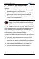
Motherboard Description 1-3 SY-7VCA HANDLING THE MOTHERBOARD To avoid damage to your Motherboard, follow these simple rules while unpacking: Ø Before handling the Motherboard, ground yourself by grasping an unpainted portion of the system's metal chassis. Ø Remove the Motherboard from its anti-static packaging. Hold the Motherboard by the edges and avoid touching its components. Ø Check the Motherboard for damage. If any chip appears loose, press carefully to seat it firmly in its socket.
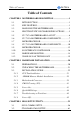
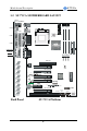
Motherboard Description SY-7VCA 1-5 SY-7VCA MOTHERBOARD LAYOUT PS/2 KB PS/2 Mouse Connector Connector USB 1 Socket 370 PRT COM1 1 3 ATX Power CPUFAN SDRAM COM2 ® VT82C694X GAME SDRAM AUDIO-OUT LINE-IN 1 MIC-IN 1 PCI Slot #1 DIMM 1 AGP Slot CODEC AC97 DIMM 2 DIMM 3 IDE 1 IDE 2 3 1 1 4 1 4 PCI Slot #3 CDIN1 Via CDIN2 ® VT82C686A JP10 1 Flash BIOS JP5 PCI Slot #2 3 PCI Slot #4 D2 D8 D1 D3 SIRCON 1 5 AMR 3V Lithium Battery 2 1 FDC1 1 5 6 10 PCI Slot #5 ISA Slot
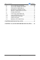
Motherboard Description SY-7VCA 1-6 SY-7VCA MOTHERBOARD COMPONENTS A B C D E W F SDRAM ® SDRAM V U G H T I ® S R Q P J K O N 7 M L
Motherboard Description A B C D E F G H I J K L M N O P Q R S T U V W X SY-7VCA Socket 370 Connector CPU Cooling Fan Connector Via 694X North Bridge chip ATX Power Supply Connector DIMM Banks Bus Mastering e-IDE/ATAPI Ports CMOS Clear Jumper Via 686A South Bridge Chip Flash BIOS USB Ports Chassis Cooling Fan Front panel connectors Serial Infrared (IrDA) Device Header Floppy Disk Drive (FDD) Port 16-bit ISA Slot 3V Lithium Battery Audio Modem Riser Slot Wake-On-LAN (WOL) Header 32-bit PCI Mastering Slots
Motherboard Description SY-7VCA 1-7 MICROPROCESSOR The motherboard supports a single Socket 370 processor. The processor’s VID pins automatically program the voltage regulator on the motherboard to the required processor voltage. In addition, the front side bus speed (100 MHz and 133 MHz) is automatically selected. The motherboard supports all current Socket 370 processor speeds, voltages, and bus frequencies. 1-7.1 Microprocessor Packaging The CPU is packaged in a 370 pin PGA package.
Motherboard Description SY-7VCA 1-8 MEMORY 1-8.1 Main Memory The motherboard has three DIMM sockets. SDRAM can be installed in one, two, or three sockets. Using the serial presence detect (SPD) data structure, programmed into an E²PROM on the DIMM, the BIOS can determine the SDRAM’s size and speed. Minimum DIMM memory size is 8 MB; maximum DIMM memory size is 256/512 MB. Memory size and speed can vary between sockets.
Motherboard Description SY-7VCA Dual copies of MA signals for improved drive Optional bank-by-bank ECC (single-bit error correction and multibit error detection) or EC(error checking only) for DRAM integrity Two-bank interleaving for 16Mbit SDRAM support Two-bank and four bank interleaving for 64Mbit SDRAM support Independent SDRAM control for each bank Seamless DRAM command scheduling for maximum DRAM bus utilization (e.g.
Motherboard Description SY-7VCA 1-9 CHIPSET Ø VT82C694X The VIA 694X is a high performance, cost-effective and energy efficient chip set for the implementation of AGP/PCI/ISA desktop personal computer systems from 66MHz, 100MHz and 133MHz based on 64-bit Socket 370 super-scalar processors. The Via 694X chip set consists of the VT82C694A system controller (510 pin BGA) and the VT82C686A PCI to ISA bridge (324 pin BGA).
Motherboard Description SY-7VCA operating environments. Both Window 95 VxD and Windows 98 /NT5.0 mini port drivers are supported for interoperability with major AGP-based 3D and DVD- capable multimedia accelerators. The VT82C694X supports two 32-bit 3.3/5V system buses (one AGP and one PCI) that are synchronous/ pseudo-synchronous to the CPU bus. The chip also contains a built-in bus-to-bus bridge to allow simultaneous concurrent operations on each bus.
Motherboard Description SY-7VCA Dynamic CKE control for powering down of the SDRAM. A separate suspend-well plane is implemented for the SDRAM control signals for Suspend-to-DRAM operation. Coupled with the VT82C686A south bridge chip, a complete power conscious PC motherboard can be implemented with no external TTLs. The Via 694X chipset is ideal for high performance, high quality, high energy efficient and high integration desktop and notebook AGP / PCI / ISA computer systems.
Motherboard Description SY-7VCA environment. 3) Keyboard controller with PS2 mouse support. 4) Real Time Clock with 256 byte extended CMOS. In addition to the standard ISA RTC functionality, the integrated RTC also includes the date alarm, century field, and other enhancements for compatibility with the ACPI standard. 5) Hardware monitoring subsystem for managing system/ motherboard voltage levels, temperatures, and fan speeds 6) Full System Management Bus (SMBus) interface.
Motherboard Description SY-7VCA controller supports type F DMA in addition to standard ISA DMA modes. Compliant with the PCI2.2 specification, the VT83C686A supports delayed transactions and remote power management so that slower ISA peripherals do not block the traffic of the PCI bus. Special circuitry is built in to allow concurrent operation without causing dead lock even in a PCIto PCI bridge environment.
Motherboard Description SY-7VCA Perpendicular recording driver support Two FDDs with drive swap support Plug and play with 48 base IO address, 12 IRQ and 4 DMA options The Setup program provides configuration option for the I/O controller. 1-10.1 Serial Ports The motherboard has two 9-pin D-Sub serial port connectors located on the back panel. The NS16C5450-compatible UARTs support data transfers at speeds up to 115.2 Kbits/sec with BIOS support. 1-10.
Motherboard Description SY-7VCA 1-10.4 PS/2 Keyboard and Mouse Interface PS/2 keyboard and mouse connectors are located on the back panel of the motherboard. The +5 V lines to keyboard and mouse connectors are protected with a fuse that prevents motherboard components from being damaged when an over-current condition occurs. Note The mouse and keyboard can be plugged into either PS/2 connector. Power to the computer should be turned off before a keyboard or mouse is connected or disconnected.
Motherboard Description SY-7VCA subsystem include: Ø An integrated ambient temperature sensor Ø Fan speed sensors, which monitor the fan 1 and fan 2 connector. Ø Power supply voltage monitoring to detect levels above or below acceptable values When suggested ratings for temperature, fan speed, or voltage are exceeded, an interrupt is activated. The hardware monitor component connects to the SMBus.
Hardware Installation SY-7VCA Chapter 2 HARDWARE INSTALLATION Congratulations on your purchase of SY-7VCA Motherboard. You are about to install and connect your new Motherboard. Note: Do not unpack the Motherboard from its protective antistatic packaging until you have made the following preparations. 2-1 PREPARATIONS Gather and prepare all the following hardware equipment to complete the installation successfully: 1. Socket 370 processor with built-in CPU cooling fan (boxed type).
Hardware Installation 2-2 SY-7VCA UNPACKING THE MOTHERBOARD When unpacking the Motherboard, check for the following items: u The SY-7VCA VT82C694X AGP/PCI Motherboard u This Quick Start Guide u The Installation CD-ROM u SOYO 3-in-1 Bonus Pack CD-ROM (Norton AntiVirus, Ghost and Virtual Drive) u One IDE Device ATA 66 Flat Cable u One Floppy Disk Drive Flat Cable Warning: Do not unpack the Motherboard from its anti-static packaging until you are ready to install it.
Hardware Installation SY-7VCA 2-3 INSTALLATION GUIDE We will now begin the installation of the Motherboard. Please follow the step-by-step procedure designed to lead you to a complete and correct installation. Warning: Turn off the power to the Motherboard, system chassis, and peripheral devices before performing any work on the Motherboard or system.
Hardware Installation SY-7VCA 2-3.1 CPU Installation Your SY-7VCA motherboard comes with a CPU retention set kit. The retention set is used to hold the processor attached to the Socket 370 CPU connector on the motherboard. Mark your CPU Frequency: Record the working frequency of your CPU that should be clearly marked on the CPU cover. FSB 66MHz 400MHz (66 x 6.0) 433MHz (66 x 6.5) 466MHz (66x7.0) 500MHz (66x7.5) 533MHz (66x8.0) 600MHz (100 x 6.0) 650MHz (100 x 6.5) 700MHz (100 x 7.0) 750MHz (100 x 7.
Hardware Installation 2. SY-7VCA Align the blunt edge of the CPU with the matching pinhole distinctive edge on the socket. 3. Seat the processor in the socket completely and without forcing. 4. Then close the socket handle to secure the CPU in place.
Hardware Installation SY-7VCA Remember to connect the CPU Cooling Fan to the appropriate power connector on the Motherboard. The fan is a key component that will ensure system stability. The fan prevents overheating, therefore prolonging the life of your CPU. 2-3.1.1 CPU Fan Installation Your Socket 370 processor kit comes with a cooling fan. Mount the fan on the processor according to the instructions provided by the manufacturer. The fan is a key component that will ensure system stability.
Hardware Installation SY-7VCA 2-3.2 SDRAM Memory Module Installation SDRAM ® SDRAM DIMM 3 DIMM 2 DIMM 1 ® Your board comes with three DIMM sockets, providing support for up to 1.5GB of main memory using unbuffered and registered DIMM modules from 8MB to 512MB. On this motherboard, DRAM speed can be set independent from the CPU front side bus speed. Depending on the DRAM clock speed setting in the BIOS setup (Chapter 3), appropriate memory modules must be used.
Hardware Installation SY-7VCA Memory Configuration Table Number of Memory Modules DIMM 1 DIMM 2 DIMM 3 RAM Type SDRAM Memory Module Size (MB) 8/16/32/64/128/256/512 MB 27
Hardware Installation SY-7VCA 2-3.3 Motherboard Connector 2-3.3.1 IDE Device Installation (HDD, CD-ROM) SDRAM ® SDRAM ® IDE 1 IDE 2 Pin -1 Primary Secondary IDE IDE This Motherboard offers two primary and secondary IDE device connectors (IDE1, IDE2). It can support up to four high-speed Ultra DMA 33/66HDD or CD-ROM.
Hardware Installation SY-7VCA 2-3.3.2 Floppy Drive Installation SDRAM ® SDRAM Pin -1 ® FDC Floppy Drive Connector The system supports 5 possible floppy drive types: 720 KB, 1.2 MB, 1.44 MB, 2.88 MB, and LS-120. Connect one side of the 34-pin flat cable to the floppy drive and plug the other end to the floppy drive connector on the Motherboard. This Motherboard can support up to 2 floppy drives.
Hardware Installation SY-7VCA 2-3.3.3 Front Panel Connections SDRAM ® SDRAM Power LED + _ Speaker _ + _ _ + + Reset PWRBT STR HDD LED LED ® Plug the computer case's front panel devices to the corresponding headers on the Motherboard. 1. Power LED Please install according to the following pin assignment: pin 1,3 are for Power LED.
Hardware Installation SY-7VCA 2. Reset Plug the Reset push-button cable into the 2-pin Reset header on the Motherboard. Pushing the Reset button on the front panel will cause the system to restart the boot-up sequence. Reset Pin Assignment 1 Power Good 3. GND Speaker Attach the 4-pin PC speaker cable from the case to the Speaker header on the Motherboard. Speaker Pin Assignment _ + +5V 4.
Hardware Installation SY-7VCA 5. ATX Power On/Off Switch Attach the 2-pin momentary type switch to the PWRBT header for turning On or Off your ATX power supply. PWRBT Pin Assignment 1 Power On/Off GND 6. STR LED The STR LED is connected to the Voltage that feeds the DIMM sockets.
Hardware Installation SY-7VCA 2-3.3.4 Back Panel Connections All external devices such as the PS/2 keyboard, PS/2 mouse, printer, modem, USB can be plugged directly onto the Motherboard back panel. Only after you have fixed and locked the Motherboard to the computer case can you start connecting the external peripheral devices. When connecting an external device, use the following figure to locate and identify which back panel connector to plug the device to.
Hardware Installation SY-7VCA 1. Onboard Serial Ports COM1/COM2 External peripherals that use serial transmission scheme include: - serial mouse, - and modem. Plug the serial device cables directly into the COM1/COM2 9-pin male connectors located at the rear panel of the Motherboard. 2. Parallel Port PRT This parallel port is used to connect the printer or other parallel devices. Plug the parallel device cable into the 25-pin female connector located at the rear panel of the Motherboard. 3.
Hardware Installation SY-7VCA 5. Universal Serial Bus USB1 (2 Ports)/USB2 (2 Ports) This Motherboard provides four USB ports for your additional devices. Plug the USB device jack into the available USB connector USB1 or USB2. - Standard device drivers come with the Win98 for commonly used USB devices. - With Win95, use the flow UHCI specifications. To use USB devices under Win95, usually you have to install the device that driver comes with the USB device you have purchased. USB2 is available.
Hardware Installation SY-7VCA 2-3.3.5 Other Connections 1. Wake-On-LAN (WOL) Attach the 3-pin connector from the LAN card which supports the WakeOn-LAN (WOL) function to the JP10 header on the Motherboard. This WOL function lets users wake up the connected computer through the LAN card.
Hardware Installation SY-7VCA 2. Infrared (IR1) Plug the 5-pin infrared device cable to the IR1 header. This will enable the infrared transfer function. This Motherboard meets both the ASKIR and HPSIR specifications. Please install according to the following pin assignment: Serial Infrared (IR1) Connector IR1 Pin Assignment 1 2 3 4 5 VCC IRRX GND IRTX 3. Other Display Cards Insert other types of VGA cards into the PCI or ISA expansion slots according to card specifications.
Hardware Installation 4. SY-7VCA Cooling Fan Installation (1) CPU Cooling Fan After you have seated the CPU properly on the processor, attach the 3-pin fan cable to the CPUFAN connector on the Motherboard. The fan will stop when the system enters into Suspend Mode. (Suspend mode can be enabled from the BIOS Setup Utility, [POWER MANAGEMENT] menu.
Hardware Installation SY-7VCA (2) Chassis Cooling Fan Some chassis also feature a cooling fan. This Motherboard features a CHAFAN connector to provide 12V power to the chassis fan. Connect the cable from the chassis fan to the CHAFAN 3-pin connector. Install according to the following pin assignment: Chassis Cooling Fan 1 GND 3 2 12V SENSOR Note: CPUFAN must be installed for this Motherboard, CHAFAN is optional.
Hardware Installation SY-7VCA 5. CD Line-in (CDIN1,CDIN2) This Motherboard provides two CD-Line in connectors. Please connect the 4-pin audio cable from your CD-ROM drive to either CDIN1 or CDIN2. (It fits in only one, depending on the cable that came with your CD-ROM drive) Please install according to the following pin assignment: CDIN1,CDIN2(CD Line-in) Pin Assigment CDIN2 4 3 2 1 GND GND Right Left GND Left CDIN1 GND Right 4 3 2 1 2-3.3.6 AGP VGA Card Insert the AGP VGA card into the AGP slot.
Hardware Installation SY-7VCA 2-3.3.7 ATX Power Supply Plug the connector from the power directly into the 20-pin male ATX PW connector on the Motherboard, as shown in the following figure. ATX Power SDRAM ® SDRAM ® Warning: Follow these precautions to preserve your Motherboard from any remnant currents when connecting to ATX power supply: Turn off the power supply and unplug the power cord of the ATX power supply before connecting to ATX PW connector.
Hardware Installation SY-7VCA Please install the ATX power according to the following pin assignment: ATX Power 12V 5VSB PW-OK GND 5V GND 5V GND 3.3V 3.3V 5V 5V -5V GND GND GND PS-ON GND Ø Pay special care to the directionality. -12V 3.3V 2-3.3.8 AMR (Audio Modem Riser)Connector This motherboard supports AMR (Audio-Modem Riser) slot that facilitates audio or modem riser card expansion.
Hardware Installation SY-7VCA 2-3.4 CMOS Clearing (JP5) After you have turned off your computer, clear the CMOS memory by momentarily shorting pins 2-3 on jumper JP5, for a few seconds. Then restore JP5 to the initial 1-2 jumper setting in order to recover and retain the default settings. Jumper JP5 can be easily identified by its white colored cap.
Hardware Installation SY-7VCA Repeat this operation until you get the following screen. 3.
Hardware Installation SY-7VCA Step 1. Select [STANDARD CMOS SETUP] Set [Date/Time] and [Floppy drive type], then set [Hard Disk Type] to “Auto”. Step 2. Select [LOAD SETUP DEFAULT] Select the “LOAD SETUP DEFAULT” menu and type “Y” at the prompt to load the BIOS optimal setup. Step 3. Select [SOYO COMBO SETUP] Move the cursor to the [CPU Frequency] field to set the CPU frequency. Available [CPU Frequency] settings on your SY-7VCA Motherboard are detailed in the following table.
Hardware Installation SY-7VCA 2-3.7 Troubleshooting at First Start Video (no display) related issues I built a new computer system using a Soyo board and nothing happens when turning it on, no video and no beeps from the PC speaker. What is happening and how can it be fixed? No screen and no beeps mean that your CPU and motherboard do not work at all. It could be that the CPU is not seated correctly or that a component on the M/B is grounded (shorted) with the case.
Hardware Installation SY-7VCA My PCI VGA card works fine with my system, but when I put in a new AGP card, it does not give me any video. Is my AGP slot bad? This is a common problem with AGP video cards. The reason is that your AGP card did not get seated into the AGP slot fully and firmly. Please push your AGP card down into the socket real hard, it should snap twice. You may have to unscrew the AGP card to allow the card to go further down. Do take care not to damage the card by using too much force.
Hardware Installation SY-7VCA What you need to do is to disable 'COM2' (or UART2 or serial port 2) in the bios under integrated peripheral setup. I have installed my modem drivers several times and I still cannot get my modem to work. Why? If you are sure that the modem driver has been installed correctly, then you need to install the south bridge driver from the SOYO CD, this is because Windows does not properly recognize relatively new chipsets. Audio Issues I do not get any sound from my sound card.
Hardware Installation SY-7VCA This is because the recorder and microphone in the Windows are not enabled. Please go to sound properties and enable them. Lock up (freeze) When I boot up my system, everything works fine. It sees my CPU and memory, detects my hard drive, floppy drive and CD-ROM but locks up at "Verify DMI pool data... ", and it won’t go any further. What should I do? Please clear the CMOS via JP5 then choose 'load setup default' in the bios and save the bios and exit.
Hardware Installation SY-7VCA 2-3.9 Debug LEDs The Debug LEDs give an indication of the status of the system during boot-up. If the system does not boot-up properly, use the table below to find out at what point in boot-up sequence the problem arises. A x means the LED is off, a L means the LED is lit. Code Explanation X X X L D8 D3 D2 D1 X X L X D8 D3 D2 D1 X X L L D8 D3 D2 D1 Initialization of the chipset.
Hardware Installation SY-7VCA You are now ready to configure your system with the BIOS setup program.
BIOS Setup Utility SY-7VCA Chapter 3 BIOS SETUP UTILITY This Motherboard's BIOS setup program uses the ROM PCI/ISA BIOS program from Award Software Inc. Phoenixnet Graphical Launch Screen The graphical launch screen displays a graphical screen to the user early in the boot process, as the first image displayed on the screen. This display remains on the screen throughout the normal BIOS initialization phase called POST.
BIOS Setup Utility SY-7VCA If the user wants to see the old boot-up screen, pressing the TAB key will switch the screen mode back to the conventional boot-up screen. The PhoenixNet BIOS will put several Icons on the windows desktop after windows is installed for the first time. Clicking these items will allow the user to go to the respective websites, including the SOYO website. If the user does not need these icons they can be removed. To enter the Award BIOS program's Main Menu: 1.
BIOS Setup Utility SY-7VCA Hot Keys: Function keys give you access to a group of commands throughout the BIOS utility. Function Command F1 F5 F6 F7 F10 [Esc] [Enter] General Help Previous Values Load FailSafe Defaults Load Optimized Defaults Save Exit Select [+/ –/PU/PD] Value Description Gives the list of options available for each item. Restore the old values. These are the values that the user started the current session with. Loads all items with the most conservative values.
BIOS Setup Utility SY-7VCA SAVE AND EXIT SETUP Select the [SAVE & EXIT SETUP] option from the Main Menu to save data to CMOS and exit the setup utility. This option saves all your changes and causes the system to reboot. R O M C M O S A W A R D S T A N D A R D B IO S C M O S F E A T U R E S C H IP S E T P O W E R P C I/IS A S E T U P IN T E G R A T E D P E R IP H E R A L S S U P E R V IS O R S E T U P F E A T U R E S B IO S U T IL I T Y S O F T W A R E , IN C .
BIOS Setup Utility SY-7VCA 3-1 SOYO COMBO SETUP This Motherboard does not use any hardware jumpers to set the CPU frequency. Instead, CPU settings are software configurable with the BIOS [SOYO COMBO SETUP]. After the hardware installation is complete, turn the power switch on, then press the key during the system diagnostic checks to enter the Award BIOS Setup program. The CMOS SETUP UTILITY will display on screen.
BIOS Setup Utility SY-7VCA 3-1.1 Quick CPU Frequency Setup Quick CPU Setting Frequency Setup Description 120/40 MHz 124/31 MHz 126/31 MHz 129/32 MHz 133/33 MHz 135/33 MHz 138/34 MHz 140/35 MHz 141/35 MHz 143/35 MHz 145/36 MHz 147/36 MHz 150/37 MHz 154/38 MHz 160/40 MHz 166/41 MHz Note Select the host clock of your Slot 1 processor among these values. Note: For the Via 694X chipset, 66 and 100 and 133 MHz host clock frequencies are acceptable.
BIOS Setup Utility SY-7VCA 3-1.3 L2 Cache Memory Setting Description Note CPU L2 Latency Control Default Manual If set to Default, the CPU Default default value for L2 cache latency is used. If set to manual, the ‘Latency Value’ item will allow you to specify a latency value. CPU L2 Latency Value 1~15 If the item above is set to ‘manual’, a latency value ranging from 1 to 15 can be set. The smaller the number, the faster the performance. However, the system may become unstable at higher speeds.
BIOS Setup Utility SY-7VCA 3-1.4 Quick CPU Frequency Setup (Continued) Quick CPU Frequency Setup Setting Vcore voltage Normal Adjust +1.5 % +3.0 % +4.5 % +6.0 % +7.5 % +9.0 % +10.0% Description Note Default The CPU notifies the board of what core voltage it requires by its VID outputs. The on-board voltage regulator uses the VID code to set the core voltage. If the Vcore Voltage Adjust is set to normal, the Vcore will be exactly what the VID code specifies.
BIOS Setup Utility SY-7VCA 3-1.7 System Boot Control Settings System Boot Control Settings Setting Description First /Second/Third Boot Device Floppy LS/ZIP HDD-0 SCSI CDROM HDD-1 HDD-2 HDD-3 LAN Disabled Select Your Boot Device Priority Boot Other Device Disabled Enabled Select Your Boot Device Priority OnChip Sound/Modem Disabled Auto This item allows you to control the onboard AC 97 Default audio/ MC 97 Modem.
BIOS Setup Utility SY-7VCA 3-2 STANDARD CMOS SETUP Select the [STANDARD CMOS SETUP] option from the Main Menu and press [Enter] key. CMOS Setup Utility – Copyright ( C ) 1984-1999 Award Software Standard CMOS Features Date (mm:dd:yy) Time (hh:mm:ss) Fri, Jan 1 1999 1 : 22 : 12 4 IDE Primary Master 4 IDE Primary Slave 4 IDE Secondary Master 4 IDE Secondary Slave Press Enter None Press Enter None Press Enter None Press Enter None Drive A Drive B Floppy 3 Mode Support 1.44M, 3.5 in.
BIOS Setup Utility SY-7VCA 3-2.2 Hard Disks Type & Mode Choose the type and mode for the hard disks that you have already installed. Primary Setting (Secondary) Master & Slave IDE HDD Auto- Press Enter Detection IDE Primary Slave (User Type) Auto Access Mode Auto User None Normal LBA Large Description Note To auto-detect the HDD’s size, head …on this channel BIOS detects hard disk type Default automatically. User defines the type of hard disk. BIOS detects hard disk mode automatically.
BIOS Setup Utility SY-7VCA 3-2.4 Others Optional Setting Description Note Video EGA/VGA CGA 40 CGA 80 MONO (Monochrome) Select the video mode. Halt On ALL Errors No Errors All, But Keyboard All, But Diskette All, But Disk/Key When the BIOS detects system Default errors, this function will stop the system. Select which type of error will cause the system halt.
BIOS Setup Utility SY-7VCA 3-3 ADVANCED BIOS FEATURES Select the [Advanced BIOS Features] option from the Main Menu and press [Enter] key.
BIOS Setup Utility SY-7VCA 3-3.1 Virus Warning Anti - Virus Protection Setting Disabled Enabled Description Note If set to enabled, the Paragon Anti-Virus. Function will scan Default your boot drive for boot virusses. If a boot virus is detected, the BIOS will display a warning message. 3-3.2 Cache Memory Options CPU Internal Cache Setting Description Note Disabled Enabled Enables the CPU's internal Default cache. Disabled Enabled Enables the external memory. External Cache Default 3-3.
BIOS Setup Utility SY-7VCA 3-3.6 Gate A20 Options Setting Gate A20 Options Normal Fast Description Lets chipset control GateA20. A pin in the keyboard controller controls GateA20. Note Default 3-3.7 Typematic Settings Typematic Settings Setting Description Note Typematic Rate Setting Disabled Keystrokes repeat at a rate Default determined by the keyboard. Enabled When enables , the typematic rate and typematic delay can be selected.
BIOS Setup Utility SY-7VCA 3-3.8 Security Option Use this feature to prevent unauthorized system boot-up or use of BIOS Setup. The following table describes the security settings. Setting Description System Each time the system is booted, the Security Option password prompt appears. Setup If a password is set, the password prompt only appears when you attempt to enter the BIOS Setup program. 3-3.
BIOS Setup Utility SY-7VCA 3-4 ADVANCED CHIPSET FEATURES Caution: Change these settings only if you are already familiar with the Chipset. The [Advanced Chipset Features] option changes the values of the chipset registers. These registers control the system options in the computer.
BIOS Setup Utility SY-7VCA After you have completed the changes, press [Esc] and follow the instructions on your screen to save your settings or exit without saving. The following table describes each field in the Advanced Chipset Features Menu and how to configure each parameter. 3-4.
BIOS Setup Utility SY-7VCA CHIPSET FEATURES SETUP (Continued) CHIPSET FEATURES Setting CPU In Order 4 Level Queue Size 1 Level System BIOS Disabled Cacheable Enabled Video RAM Cacheable Disabled Enabled Description Note This item is related to cache performance. A queue size of 4 gives highest performance. Default The ROM area F0000H-FFFFFH is Default cacheable. When synchronous DRAM is Default installed, the number of clock cycles of CAS latency depends on the DRAM timing.
BIOS Setup Utility SY-7VCA CHIPSET FEATURES SETUP (Continued) CHIPSET FEATURES AGP Fast Write Setting Description Disabled Enabled The VIA chipset will use fast write Default to AGP if this item is enabled. Not all AGP cards support fast write. OnChip USB Disabled Enabled This should be enabled if your system has a USB installed on the Default system board and you want to use it. Even when so equipped, if you add a higher performance controller, you will need to disable this feature.
BIOS Setup Utility SY-7VCA CHIPSET FEATURES SETUP (Continued) CHIPSET FEATURES PCI Delay Transaction Setting Description Disabled Enabled The chipset has an embedded 32-bit posted write buffer to support delay Default transactions cycles. Select Enabled to support compliance with PCI specification version 2.1. PCI#2 Access Disabled #1 Retry Enabled When disabled, PCI#2 will not be disconnected until access finishes Default (difault).
BIOS Setup Utility SY-7VCA 3-5 INTEGRATED PERIPHERALS Caution: Change these settings only if you are already familiar with the Chipset. The [INTEGRATED PERIPHERALS] option changes the values of the chipset registers. These registers control the system options in the computer. The following screen shows setup default settings.
BIOS Setup Utility SY-7VCA The following tables describe each field in the INTEGRATED PERIPHERALS Menu and provide instructions on how to configure the IDE controls, FDC controls, and the onboard serial and parallel ports. 3-5.
BIOS Setup Utility SY-7VCA 3-5.4 FDC Controls FDC Controls Setting Description Onboard FDD controller Disabled Turn off the on-board floppy controller Use the on-board floppy Default controller Enabled Note 3-5.5 Onboard Serial Ports Onboard Serial Ports Setting Onboard Serial Port 1 / Serial Port 2 Disabled 3F8/IRQ4 2F8/IRQ3 3E8/IRQ4 2E8/IRQ3 Auto UART 2 Mode Standard HPSIR ASKIR Description Note Choose serial port 1 & 2's I/O address.
BIOS Setup Utility SY-7VCA 3-5.6 Onboard Parallel Ports Onboard Parallel Ports Setting Description Note Onboard Parallel Port Disabled 378/IRQ7 3BC/IRQ7 278/IRQ5 Choose the printer I/O address. Default Parallel Port Mode Normal EPP ECP ECP+EPP The mode depends on your Default external device that connects to this port. If [Parallel Port Mode] is set to [ECP] mode 3 1 ECP Mode use DMA Choose DMA3 Choose DMA1 Default If [Parallel Port Mode] is set to [EPP] mode Parallel Port EPP TYPE EPP 1.
BIOS Setup Utility SY-7VCA Onboard Legacy Audio (Continued) This field controls the onboard legacy audio. Setting Description MPU-401 Disabled Enabled Set this item to enabled to make use of MIPI. Note Default MPU-401 I/O 330-333H Select the I/O address for your MIDI Default Address 330-303H functionality. 310-313H 320-323H Game Port (200-207H) Disabled Enabled Set this item to enabled to make use of the game port.
BIOS Setup Utility SY-7VCA 3-6 POWER MANAGEMENT SETUP The [POWER MANAGEMENT SETUP] sets the system's power saving functions.
BIOS Setup Utility SY-7VCA After you have completed the Power Management Setup, press [Esc] to return to the Main Menu. 3-6.1 Power Management Controls Power Setting Management Controls ACPI Suspend S1 (POS) S3 (STR) Type Description Note The system will enter the S1 state during suspend. (Low latency wake up) Default Power Management Lets you define the HDD and system power down times.
BIOS Setup Utility SY-7VCA Power Management Controls (Continued) Power Management Controls MODEM Use IRQ Setting 3 3-11, NA Description Note Assigns an IRQ# to the modem Default device. Soft-Off by PWR-BTTN Instant-off Default Delay 4 Sec. Turns off the system power 4 seconds after pushing the power button.
BIOS Setup Utility SY-7VCA Wake Up Events Setting Description Note PowerOn by PCI Card Disabled Enabled If enabled any PCI interrupt will wake up the system. Default Modem Ring Resume Disabled Enabled An input signal on the serial Ring Indicator (RI) line (in other words, an incoming call on the modem) awakens the system from a soft off state. Resume by Alarm Disabled Enabled The system ignores the alarm. Default Set alarm to power on the system by the date (1-31) or time (hh:mm:ss).
BIOS Setup Utility SY-7VCA 3-7 PNP/PCI CONFIGURATION SETUP This option sets the Motherboard's PCI Slots.
BIOS Setup Utility SY-7VCA 3-7.1 PNP/PCI Configuration Controls PNP/PCI Controls Setting Description PnP OS Installed Yes Set this field to [Yes] if you are running Windows 95, which is PnP compatible. If the OS you are running Default (If there is any does not support PnP doubt, set this configuration. No Note field to [No]) Reset Configuration Data Disabled Retain PnP configuration Default data in BIOS. Enabled Reset PnP configuration data in BIOS.
BIOS Setup Utility SY-7VCA PNP/PCI Configuration Setup (Continued) PNP/PCI Setup Setting Description Note How to set the BIOS to release the IRQ to the PnP Interrupt pool: PnP / PCI configuration Integrated Peripherals IRQ 15: PCI / ISA PnP On-Chip Secondary PCI IDE: disabled IRQ 14: PCI / ISA PnP On-Chip Primary PCI IDE: disabled Interrupt 12 will be released by the PnP IRQ 12 IRQ 12: PCI / ISA PnP BIOS automatically if the PS/2 Mouse Port is not used.
BIOS Setup Utility SY-7VCA 3-7.2 MULTI I/O ADDRESSES Default settings for multi-I/O addresses are as follows: Port I/O Address IRQ Status LPT1 378H 7 ECP/EPP COM1 3F8H 4 COM2 2F8H 3 Warning: If a default I/O address conflicts with other I/O cards such as sound card, you must change one of the I/O addresses to remedy to this address conflict. (I/O addresses can be adjusted from the BIOS Setup Utility) 3-8 PC HEALTH STATUS This option sets the Motherboard's PC Health Status.
BIOS Setup Utility SY-7VCA 3-8.1 CPU Device Monitoring CPU Device Monitoring Setting Description Current CPU Temp. °C/°F Show the current status of CPU temperature. Current System Temp. °C/°F Show the current status of the system temperature. Current CPUFAN Speed °C/°F Show the current status of CPU Fan Current CHSFAN Speed °C/°F Show the current status of the chassis Fan Vcore, 2.5V, 3.3V, +5V, +12V V Show the current voltage status.
BIOS Setup Utility SY-7VCA 3-9 LOAD FAIL-SAFE DEFAULTS Select the [Load Fail-Safe Defaults] option from the Main Menu to load the system values you have previously saved. This option is recommended if you need to reset the system setup and to retrieve the old values.
BIOS Setup Utility SY-7VCA 3-10 LOAD OPTIMIZED DEFAULTS Select the [Load Optimized Defaults] option from the Main Menu to load the system values you have previously saved. This option is recommended if you need to reset the system setup and to retrieve the old values.
BIOS Setup Utility SY-7VCA 3-11 SUPERVISOR PASSWORD Based on the setting you have made in the [Security Option] of the [BIOS FEATURES SETUP] section, the password prevents access to the system or the setup program by unauthorized users. Follow this procedure to set a new password or disable the password: 1. Choose [BIOS FEATURES SETUP] in the Main Menu and press [Enter]. Select the [Security Options] item and set the field to: a. [System]: The password is required every time the system is booted.
BIOS Setup Utility 3. SY-7VCA Enter your new password and press [Enter]. The following message appears, prompting to confirm the new password: Confirm Password: 4. Re-enter your password and then press [Enter] to exit to the Main Menu. This diagram outlines the password selection procedure: Press: ↔the password entering Type Typethe thePassword Password and Press: Press: ↔ ROM PCI/ISA BIOS Press without CMOS SETUP UTILITYWithout entering password AWARD SOFTWARE, INC.
BIOS Setup Utility SY-7VCA 3-13 IDE HDD AUTO DETECTION This Main Menu function automatically detects the hard disk type and configures the [Standard CMOS Features] accordingly.
Drivers installation SY-7VCA Chapter 4 DRIVERS INSTALLATION Your SY-7VCA Motherboard comes with a CD-ROM labeled "SOYO CD." The SOYO CD contains the user's manual file for your new Motherboard, the drivers software available for installation, and a database in HTML format with information on SOYO Motherboards and other products. Step 1. Insert the SOYO CD into the CD-ROM drive The SOYO CD will auto-run, and the SOYO CD Start Up Menu will be as shown.
Drivers installation SY-7VCA If you use Windows 95 or 98, the SOYO CD Start Up Program automatically detects which SOYO Motherboard you own and displays the corresponding model name. The user's manual files included on the SOYO CD are in PDF (Postscript Document) format. In order to read a PDF file, the appropriate Acrobat Reader software must be installed in your system.
Drivers installation SY-7VCA Step 2. Install Drivers Click the Install Drivers button to display the list of drivers software that can be installed with your Motherboard. The Start Up program displays the drivers available for the particular model of Motherboard you own. We recommend that you only install those drivers.
Drivers installation SY-7VCA This driver will make the necessary changes to the Windows registry, in order to make sure that Windows has no problems recognizing your VIA chipset. IRQ remapping utility (This driver is installed automatically) This utility will remap the IRQ lines to make sure that everything functions properly under Windows. Ø VIA Ac97 Codec Driver for Win 95 You have to install the drivers before installing any application for the Ac97 codec.
Via SoundChip Drivers installation SY-7VCA Chapter 5 VIA SOUNDCHIP DRIVERS INSTALLATION Most of the drivers on this CD can be installed automatically. Run the SOYO-CD program and click the 'install drivers' button. Now a list of the available drivers will be displayed. Select a driver and click OK to install the driver. Some drivers will have to be installed by hand. See the explanation below.
Via SoundChip Drivers installation SY-7VCA VIA Soundchip drivers for Windows 2000 For windows 2000, after installation of windows go to 'my computer' and select 'properties'. Now the 'system properties' menu will be shown. Select 'hardware' tab, and click the 'device manager' button. On the device manager a question mark will be shown under 'multimedia audio controller'. Do not remove this entry! To change the driver, click this entry and select properties -> driver -> update driver.
98