SY-K7ADA Motherboard **************************************************** AMD® Athlon/Duron Processor supported ALI MAGIK1 AGP/PCI Motherboard 266/200 MHz Front Side Bus supported ATX Form Factor **************************************************** User's Manual
SOYO™ SY-K7ADA Copyright © 2001 bySoyo Computer Inc. Trademarks: Soyo is the registered trademark of Soyo Computer Inc. All trademarks are the properties of their owners. Product Rights: All names of the product and corporate mentioned in this publication are used for identification purposes only. The registered trademarks and copyrights belong to their respective companies. Copyright Notice: All rights reserved. This manual has been copyrighted by Soyo Computer Inc.
Table of Contents SY-K7ADA Table of Contents CHAPTER 1 MOTHERBOARD DESCRIPTION...............................1 1-1 1-2 1-3 INTRODUCTION ............................................................1 KEY FEATURES .............................................................1 ELECTROSTATIC DISCHARGE PRECAUTIONS .........4 1-4 1-5 1-6 1-7 1-8 1-9 SY-K7ADA MOTHERBOARD LAYOUT .......................5 SY-K7ADA MOTHERBOARD COMPONENTS ........................6 MICROPROCESSOR.....................................
Table of Contents SY-K7ADA 3-2 3-3 3-4 3-5 3-6 3-7 ADVANCED BIOS FEATURES.....................................54 ADVANCED CHIPSET FEATURES..............................59 INTEGRATED PERIPHERALS .....................................62 POWER MANAGEMENT SETUP ................................66 PNP/PCI CONFIGURATION SETUP.............................70 PC HEALTH STATUS....................................................73 3-8 3-9 3-10 3-11 3-12 3-13 LOAD FAIL-SAFE DEFAULTS..................................
Motherboard Description SY-K7ADA Chapter 1 MOTHERBOARD DESCRIPTION 1-1 INTRODUCTION The SY-K7ADA AGP/PCI Motherboard is a high-performance Socket 462 ATX form-factor system board. Using ALI Chipset technology. This Motherboard is fully compatible with industry standards and adds many technical enhancements. 1-2 KEY FEATURES Ø CPU SUPPORT The SY-K7ADA supports THE FOLLOWING AMD ® CPUs: n Supports 200MHz Front Side Bus DDR(Double Data Rate) transfer on Athlon(750MHz~1.
Motherboard Description n Ø SY-K7ADA CPU Multiplier EXPANDABILITY The SY-K7ADA provides all the standard expansion slots, and many more additional expansion features: u Expansion slots n 1 x 32-bit bus master AGP slot n 5 x 32-bit bus master PCI slots u n n n n n n n n Enhanced IO Floppy disk controller 2x EIDE controllers with support for up to 4 Ultra DMA 33/66/100 devices Standard/EPP/ECP parallel port 2x 16550 compatible serial ports IrDA compatible infrared port 6x USB (Universal Serial Bus) co
Motherboard Description Ø SY-K7ADA ADVANCED FUNCTIONS The SY-K7ADA supports advanced functions such as: n Wake-On-LAN Supports Wake-On-LAN (Some advanced network cards can wake the system up over the network, the WOL connector is provided by the SY-K7ADA to support this function). n Multiple boot The SY-K7ADA supports booting from devices such as CD-ROM, FLOPPY DRIVE & HDD, LS120, SCSI, ZIP.
Motherboard Description Ø SY-K7ADA CPU FSB frequency PCI clock AGP Clock SDRAM Clock HANDLING THE MOTHERBOARD To avoid damage to your Motherboard, follow these simple rules while unpacking: Ø Ø Ø Before handling the Motherboard, ground yourself by grasping an unpainted portion of the system's metal chassis. Remove the Motherboard from its anti-static packaging. Hold the Motherboard by the edges and avoid touching its components. Check the Motherboard for damage.
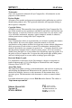
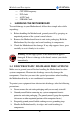
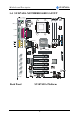
Motherboard Description SY-K7ADA 1-4 SY-K7ADA MOTHERBOARD LAYOUT PS/2 KB PS/2 Mouse Connector Connector JP1 1 USB 1_2 3 FJ1 PRT COMA COMB AGAME SDRAM ALi ATX Power AOUT ® M1647 VJ1 AIN SDRAM AMIC IDE 2 IDE 1 3 1 ALi M5879 VJ2 AGP Slot 4 Sigmatel STAC9700 ALi M5819 PCI Slot #1 Flash BIOS 1 CDIN1 PCI Slot #2 ALi ® RJ2 RJ1 FLP M1535D+ PCI Slot #3 PCI Slot #4 3 1 3V Lithium Battery PCI Slot #5 RJ3 3 JP5 1 Back Panel 3 JP10 1 1112 13 14 15 16 17 18 19 20 1 2 3 4 5 W
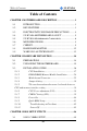
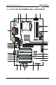
Motherboard Description SY-K7ADA 1-5 SY-K7ADA MOTHERBOARD COMPONENTS A B C D E F AE G SDRAM ® SDRAM H I J K AD AC AB AA L ® Z M Y X N O W V P U T S R 6 Q
Motherboard Description A B C D E F G H I J K L M N O P Q R S T U V W X Y Z AA AB AC AD AE SY-K7ADA K/B Power-On setting Jumper CPU Vcore adjustment setting switch Socket 462 Connector DIMM Banks CPU Cooling Fan Connector CPU FSB adjustment setting switch Bus Mastering E-IDE/ATAPI Ports ALi M1647 North Bridge chip SYS Cooling Fan CPU Vcore setting Jumper 32-bit AGP 1X/2X/4X Slot Floppy Disk Drive (FDD) Port ALi M1535D+ South Bridge chip 32-bit PCI Mastering Slots Serial Infrared (IrDA) Device Header Chas
Motherboard Description SY-K7ADA 1-6 MICROPROCESSOR The motherboard supports a single Socket 462 processor. The processor’s VID pins automatically program the voltage regulator on the motherboard to the required processor voltage. In addition, the front side bus speed (200/266 MHz ) is automatically selected. The motherboard supports all current Socket 462 processor speeds, voltages, and bus frequencies. 1-6.1 Microprocessor Packaging The CPU is packaged in a 462 pin PGA package.
Motherboard Description 1-7 SY-K7ADA CHIPSET Ø ALi M1647 Overview The M1647 is a high performance, high value North Bridge that supports all Athlon family processors. Internally all 128-bit architecture with optimization for S2K bus, DDR and AGP4X interface, the M1647 has outstanding high system performance under all types of system operations.
Motherboard Description SY-K7ADA This boosts the graphic benchmarks into another era for professional graphics usage. The M1647 design is capable of supporting 28 outstanding AGP commands (depth of command queue=28) and buffering 64QW for AGP master read operations. The M1647 is fully compliant with the PCI 2.2 specification. Flexible PCI latency control allows the M1647 to achieve improved system performance.
Motherboard Description SY-K7ADA three full function universal asynchronous receiver/transmitters (UARTs), a flexible high performance internal data separator with send/receive 16 byte FIFOs. It is also suitable for notebook computers since it has Fast Infra Red for wireless communications with other devices. It can swap the floppy drives A & B. It supports SPP, PS/2, EPP and ECP parallel port. It also has a programmable baud rate generator.
Motherboard Description SY-K7ADA Legacy-Free and Legacy Reduction specification of PC2001. 1-7.1 PS/2 Keyboard and Mouse Interface PS/2 keyboard and mouse connectors are located on the back panel of the motherboard. The +5 V lines to keyboard and mouse connectors are protected with a fuse that prevents motherboard components from being damaged when an over-current condition occurs. Note The mouse and keyboard can be plugged into either PS/2 connector.
Motherboard Description SY-K7ADA 1-9 WAKE ON LAN TECHNOLOGY Wake on LAN technology enables remote wakeup of the computer through a network. Wake on LAN technology requires a PCI add-in network interface card (NIC) with remote wakeup capabilities. The remote wakeup connector on the NIC must be connected to the onboard Wake on LAN connector. The NIC monitors network traffic at the Ethernet interface; upon detecting a Magic Packet, the NIC asserts a wakeup signal that powers up the computer.
Hardware Installation SY-K7ADA Chapter 2 HARDWARE INSTALLATION Congratulations on your purchase of SY-K7ADA Motherboard. You are about to install and connect your new Motherboard. Note: Do not unpack the Motherboard from its protective antistatic packaging until you have made the following preparations. 2-1 PREPARATIONS Gather and prepare all the following hardware equipment to complete the installation successfully: 1. Socket 462 processor with built-in CPU cooling fan (boxed type).
Hardware Installation 2-2 SY-K7ADA UNPACKING THE MOTHERBOARD When unpacking the Motherboard, check for the following items: u The SY-K7ADA ALi MAGIK1 AGP/PCI Motherboard u The Quick Start Guide u The Installation CD-ROM u SOYO Bonus Pack CD-ROM u One IDE Device ATA33/66/100 Flat Cable u One Floppy Disk Drive Flat Cable u One Heat Sink Compound Warning: Do not unpack the Motherboard from its anti-static packaging until you are ready to install it.
Hardware Installation SY-K7ADA 2-3 INSTALLATION GUIDE We will now begin the installation of the Motherboard. Please follow the step-by-step procedure designed to lead you to a complete and correct installation. Warning: Turn off the power to the Motherboard, system chassis, and peripheral devices before performing any work on the Motherboard or system.
Hardware Installation SY-K7ADA 2-3.1 CPU Installation Your SY-K7ADA motherboard comes with a CPU retention set kit. The retention set is used to hold the processor attached to the Socket 462 CPU connector on the motherboard. Mark your CPU Frequency: Record the working frequency of your CPU that should be clearly marked on the CPU cover. 200MHz FSB DDR transfer on Athlon 750 MHz (100 x 7.5) 800 MHz (100 x 8.0) 950 MHz (100 x 9.5) 1000 MHz (100 x 10.0) 850 MHz (100 x 8.5) 1.1GHz (100 x 11.
Hardware Installation SY-K7ADA 2. Align the blunt edge of the CPU with the matching pinhole distinctive edge on the socket. 3. Seat the processor in the socket completely and without forcing. 4. Then close the socket handle to secure the CPU in place.
Hardware Installation SY-K7ADA Remember to connect the CPU Cooling Fan to the appropriate power connector on the Motherboard. The fan is a key component that will ensure system stability. The fan prevents overheating, therefore prolonging the life of your CPU.
Hardware Installation SY-K7ADA 2-3.2 DDR SDRAM Memory Module Installation SDRAM ® SDRAM ® Your board comes with three DIMM sockets, providing support for up to 3GB of main memory using DDR RAM modules from 4Mb to 512Mb. On this motherboard, DRAM speed can be set independent from the CPU front side bus speed. Appropriate memory modules must be used. Supports DDR frequency 100/133 MHz.
Hardware Installation SY-K7ADA Memory Configuration Table Number of Memory Modules DIMM 1 DIMM 2 DIMM 3 RAM Type DDR SDRAM Memory Module Size 4/16/32/64/128/256/512 Mbit 21
Hardware Installation SY-K7ADA 2-3.3 Motherboard Connector SDRAM ® SDRAM ® Pin-1 IDE 2 IDE 1 Secondary Primary IDE IDE 2-3.3.1 IDE Device Installation (HDD, CD-ROM) This Motherboard offers two primary and secondary IDE device connectors (IDE1, IDE2). It can support up to four high-speed Ultra DMA 33/66/100HDD or CD-ROM.
Hardware Installation SY-K7ADA 2-3.3.2 Floppy Drive Installation SDRAM ® SDRAM Pin -1 ® FDC Floppy Drive Connector The system supports 5 possible floppy drive types: 720 KB, 1.2 MB, 1.44 MB, 2.88 MB, and LS-120. Connect one side of the 34-pin flat cable to the floppy drive and plug the other end to the floppy drive connector on the Motherboard. This Motherboard can support up to 2 floppy drives.
Hardware Installation SY-K7ADA 2-3.3.3 Front Panel Connections SDRAM 1112 13 14 15 16 17 18 19 20 ® SDRAM 1 2 3 4 5 9 10 ® Plug the computer case's front panel devices to the corresponding headers on the Motherboard. 1. Power LED Please install according to the following pin assignment: pin 1,3 are for Power LED.
Hardware Installation SY-K7ADA 2. Reset Plug the Reset push-button cable into the 2-pin Reset header on the Motherboard. Pushing the Reset button on the front panel will cause the system to restart the boot-up sequence. Reset Pin Assignment Pin1 Pin2 Power RST GND 3. Speaker Attach the 4-pin PC speaker cable from the case to the Speaker header on the Motherboard. Speaker Pin Assignment Pin17 + Power Pin18 Pin19 _ Pin20 Speaker out NC NC 4.
Hardware Installation SY-K7ADA 5. ATX Power On/Off Switch Attach the 2-pin momentary type switch to the PWRBT header for turning On or Off your ATX power supply.
Hardware Installation SY-K7ADA 2-3.3.4 Back Panel Connections All external devices such as the PS/2 keyboard, PS/2 mouse, printer, modem, USB1, USB2 can be plugged directly onto the Motherboard back panel. Only after you have fixed and locked the Motherboard to the computer case can you start connecting the external peripheral devices. When connecting an external device, use the following figure to locate and identify which back panel connector to plug the device to.
Hardware Installation SY-K7ADA 1. Onboard Serial Ports COM1/COM2 External peripherals that use serial transmission scheme include: - serial mouse, - and modem. Plug the serial device cables directly into the COM1/COM2 9-pin male connectors located at the rear panel of the Motherboard. 2. Parallel Port PRT This parallel port is used to connect the printer or other parallel devices. Plug the parallel device cable into the 25-pin female connector located at the rear panel of the Motherboard. 3.
Hardware Installation SY-K7ADA 5. Universal Serial Bus (USB3, USB4/USB5, USB6) This Motherboard provides four USB ports for your additional devices. Plug the USB device jack into the available USB connector USB3, USB4, USB5 and USB6 via USB cable. Standard device drivers come with the Win98 for commonly used - USB devices. With Win95, use the flow OpenHCI 1.0a specifications. To use USB devices under Win95, usually you have to install the device that driver comes with the USB device you have purchased.
Hardware Installation SY-K7ADA 2-3.3.5 Other Connections 1. Wake-On-LAN (WOL) Attach the 3-pin connector from the LAN card which supports the WakeOn-LAN (WOL) function to the JP10 header on the Motherboard. This WOL function lets users wake up the connected computer through the LAN card.
Hardware Installation SY-K7ADA 2. Infrared Plug infrared device cable to the SIRCON header. This will enable the infrared transfer function. This Motherboard meets both the IrDA 1.0 (SIR) and IrDA 1.1 (FIR and MIR) specifications. Supports sharp-IR. Please install according to the following pin assignment: Standard Infrared (SIRCON) Connector SIRCON Pin Assignment 1 2 3 4 5 6 +5V IRRX GND OVCROFF IRTX 3.
Hardware Installation 4. SY-K7ADA Cooling Fan Installation (1) CPU Cooling Fan After you have seated the CPU properly on the processor, attach the 3-pin fan cable to the CPUFAN connector on the Motherboard. The fan will stop when the system enters into Suspend Mode. (Suspend mode can be enabled from the BIOS Setup Utility, [POWER MANAGEMENT] menu.
Hardware Installation SY-K7ADA (2) Chassis Cooling Fan Some chassis also feature a cooling fan. This Motherboard features a CHAFAN connector to provide 12V power to the chassis fan. Connect the cable from the chassis fan to the CHAFAN 3-pin connector. Install according to the following pin assignment: Chassis Cooling Fan CHAFAN1 Pin Assignment 1 PWM2 2 +12V 3 SENSOR (3) Chipset Cooling Fan Some chipset also feature a cooling fan.
Hardware Installation SY-K7ADA 5. CD Line-in (CDIN1) This Motherboard provides two CD-Line in connectors. Please connect the 4-pin audio cable from your CD-ROM drive to either CDIN1. (It fits in only one, depending on the cable that came with your CD-ROM drive) Please install according to the following pin assignment: CD-IN: CDIN1 4 Right 3 GND 2 GND 1 Left 2-3.3.6 AGP VGA Card Insert the AGP VGA card into the AGP slot.
Hardware Installation SY-K7ADA 2-3.3.7 ATX Power Supply ATX Power SDRAM ® SDRAM ® Plug the connector from the power directly into the 20-pin male ATX PW connector on the Motherboard, as shown in the following figure. Warning: Follow these precautions to preserve your Motherboard from any remnant currents when connecting to ATX power supply: Turn off the power supply and unplug the power cord of the ATX power supply before connecting to ATX PW connector.
Hardware Installation SY-K7ADA ATX Power 12V 5VSB PW-OK GND 5V 5V -5V GND GND 5V GND 5V GND PS-ON GND -12V 3.3V GND 3.3V 3.3V Ø Pay special care to the directionality. 2-3.4 Jumper Setting 2-3.4.1 Multiplier Adjustment Setting (RJ1) For certain AMD CPUs, the multiplier is not locked such that setting a multiplier higher than specified on the CPU is possible. For technical details read the following: Refer to the following table to set the Frequency Multiplier of your CPU.
Hardware Installation SY-K7ADA If you set ratio to manual and configure the RJ1 DIP Switch to the settings that match your CPU speed, as follow table: RJ1 5 5.5 6 6.5 7 7.5 8 8.5 1 On Off On Off On Off On Off 2 On On Off Off On On Off Off 3 Off Off Off Off On On On On 4 On On On On Off Off Off Off RJ1 9 9.5 10 10.5 11 11.5 12 12.
Hardware Installation SY-K7ADA 2-3.5 The synchronous/asynchronous clock mode between CPU and memory interface setting The FSB Frequency can be set through DIP switch FJ1 or BIOS and it may therefore differ from the Frequency the CPU specifies. Doing so may however force your CPU to operate out of its specifications and therefore SOYO can not guarantee the proper functioning of your system.
Hardware Installation SY-K7ADA If you set status to manual and configure VJ1 switch to the settings that match your CPU voltage as follow table: 1 2 3 4 5 1 2 3 4 VJ1 VJ1 Auto OFF OFF OFF OFF OFF 1.475 OFF OFF OFF OFF 1.100 ON OFF OFF OFF OFF 1.500 ON OFF OFF OFF 1.125 OFF ON OFF OFF OFF 1.525 OFF ON OFF OFF 1.150 ON ON OFF OFF OFF 1.550 ON ON OFF OFF 1.175 OFF OFF ON OFF OFF 1.575 OFF OFF ON OFF 1.200 ON OFF ON OFF OFF 1.600 ON OFF ON OFF 1.225 OFF ON ON OFF OFF 1.625 OFF ON ON OFF 1.
BIOS Setup Utility SY-K7ADA 2-3.8 Power On You have now completed the hardware installation of your Motherboard successfully. 1. Turn the power on 2. To enter the BIOS Setup Utility, press the key while the system is performing the diagnostic checks, Note: If you have failed to enter the BIOS, wait until the boot up sequence is completed. Then push the RESET button and press key again at the beginning of boot-up, during diagnostic checks.
BIOS Setup Utility SY-K7ADA 2-3.9 Quick BIOS Setup This Motherboard does not use any hardware jumpers to set the CPU frequency. Instead, CPU settings are software configurable with the BIOS [SOYO COMBO SETUP]. The [SOYO COMBO SETUP] menu combines the main parameters that you need to configure, all in one menu, for a quick setup in BIOS. After the hardware installation is complete, turn the power switch on, then press the key during the system diagnostic checks to enter the Award BIOS Setup program.
BIOS Setup Utility SY-K7ADA 2-3.10 Troubleshooting at First Start Video (no display) related issues I built a new computer system using a Soyo board and nothing happens when turning it on, no video and no beeps from the PC speaker. What is happening and how can it be fixed? No screen and no beeps mean that your CPU and motherboard do not work at all. It could be that the CPU is not seated correctly or that a component on the M/B is grounded (shorted) with the case.
BIOS Setup Utility SY-K7ADA My PCI VGA card works fine with my system, but when I put in a new AGP card, it does not give me any video. Is my AGP slot bad? This is a common problem with AGP video cards. The reason is that your AGP card did not get seated into the AGP slot fully and firmly. Please push your AGP card down into the socket real hard, it should snap twice. You may have to unscrew the AGP card to allow the card to go further down. Do take care not to damage the card by using too much force.
BIOS Setup Utility SY-K7ADA What you need to do is to disable 'COM2' (or UART2 or serial port 2) in the bios under integrated peripheral setup. I have installed my modem drivers several times and I still cannot get my modem to work. Why? If you are sure that the modem driver has been installed correctly, then you need to install the south bridge driver from the SOYO CD, this is because Windows does not properly recognize relatively new chipsets. Audio Issues I do not get any sound from my sound card.
BIOS Setup Utility SY-K7ADA This is because the recorder and microphone in the Windows are not enabled. Please go to sound properties and enable them. Lock up (freeze) When I boot up my system, everything works fine. It sees my CPU and memory, detects my hard drive, floppy drive and CD-ROM but locks up at "Verify DMI pool data... ", and it won’t go any further. What should I do? Please clear the CMOS ALi JP5 then choose 'load fail-safe default' in the bios and save the bios and exit.
BIOS Setup Utility SY-K7ADA Chapter 3 BIOS SETUP UTILITY This Motherboard's BIOS setup program uses the ROM PCI/ISA BIOS program from Award Software Inc. To enter the Award BIOS program's Main Menu: 1. Turn on or reboot the system. 2. After the diagnostic checks, press the [Del] key to enter the Award BIOS Setup Utility.
BIOS Setup Utility SY-K7ADA Hot Keys: Function keys give you access to a group of commands throughout the BIOS utility. Function Command Description Gives the list of options available for each F1 General Help item. Previous Restore the old values. These are the values F5 Values that the user started the current session with. Load FailLoads all items with the most conservative F6 Safe Defaults values. Load F7 Optimized Loads all options with the optimize values.
BIOS Setup Utility SY-K7ADA SAVE AND EXIT SETUP Select the [SAVE & EXIT SETUP] option from the Main Menu to save data to CMOS and exit the setup utility. This option saves all your changes and causes the system to reboot. R O M C M O S A W S T A N D A R D B IO S C M O S F E A T U R E S C H IP S E T P O W E R A R D P C I/IS A U T IL I T Y S O F T W A R E , IN C .
BIOS Setup Utility SY-K7ADA 3-1 SOYO COMBO SETUP This Motherboard does not use any hardware jumpers to set the CPU frequency. Instead, CPU settings are software configurable with the BIOS [SOYO COMBO SETUP]. After the hardware installation is complete, turn the power switch on, then press the key during the system diagnostic checks to enter the Award BIOS Setup program. The CMOS SETUP UTILITY will display on screen.
BIOS Setup Utility SY-K7ADA 3-1.1 Quick CPU Frequency Setup Setting Disabled Auto Detect DIMM/PCI Clk Enabled Description Note For EMI test purpose. Default Spread Spectrum Modulated Disabled Enabled Default CPU Host/ SDRAM/PCI Clock Default 100/100/33 MHz 101/101/33 MHz 102/102/34 MHz 103/103/34 MHz 105/105/35 MHz 107/107/35 MH 110/110/36 MHz 100/133/33 MHz System Performance Normal Adjust your computer performance.
BIOS Setup Utility SY-K7ADA 3-1.3 System Boot Control Settings System Boot Control Settings Setting Description Note First /Second/Third Boot Device Floppy LS/ZIP HDD-0 SCSI CDROM HDD-1 HDD-2 HDD-3 LAN Disabled Select Your Boot Device Priority Boot Other Device Disabled Enabled Select Your Boot Device Priority ALi OnChip Audio Enabled Disabled This item allows you to Default control the onboard AC 97 audio. Default 3-1.
BIOS Setup Utility SY-K7ADA STANDARD CMOS SETUP Select the [STANDARD CMOS SETUP] option from the Main Menu and press [Enter] key. CMOS Setup Utility – Copyright ( C ) 1984-2001 Award Software Standard CMOS Features Date (mm:dd:yy) Time (hh:mm:ss) Tue, Jan 4 2001 1 : 22 : 12 4 IDE Primary Master 4 IDE Primary Slave 4 IDE Secondary Master 4 IDE Secondary Slave Menu Level None None None None Drive A Drive B Floppy 3 Mode Support 1.44M, 3.5 in.
BIOS Setup Utility SY-K7ADA 3-1.6 Hard Disks Type & Mode Choose the type and mode for the hard disks that you have already installed. Primary Setting Description Note (Secondary) Master & Slave IDE HDD Auto- Press Enter Detection IDE Primary Slave (User Type) Auto Access Mode Auto User None To auto-detect the HDD’s size, head …on this channel BIOS detects hard disk type Default automatically. User defines the type of hard disk. BIOS detects hard disk mode automatically.
BIOS Setup Utility SY-K7ADA 3-1.8 Others Optional Setting Description Note Video EGA/VGA CGA 40 CGA 80 MONO (Monochrome) Select the video mode. Default Halt On ALL Errors No Errors All, But Keyboard All, But Diskette All, But Disk/Key When the BIOS detects system Default errors, this function will stop the system. Select which type of error will cause the system halt. 3-2 ADVANCED BIOS FEATURES Select the [Advanced BIOS Features] option from the Main Menu and press [Enter] key.
BIOS Setup Utility SY-K7ADA After you have completed the changes, press [Esc] key and follow the instructions on your screen to save your settings or exit without saving. 3-2.1 Virus Warning Setting Virus Warning Disabled Enabled Description Allows you to choose the VIRUS Warning feature for IDE Hard Disk boot sector protection. If this function is enabled and someone attempt to write data into this area, BIOS will show a warning message on screen and alarm beep. Note Default 3-2.
BIOS Setup Utility SY-K7ADA 3-2.5 Boot Up NumLock Status Setting Boot Up NumLock Status On Description Note Puts numeric keypad in Default NumLock mode at boot-up. Puts numeric keypad in arrow key mode at boot-up. Off Boot Up System High Low Speed Boots at default CPU speed. Boots at AT bus speed. Default 3-2.6 Gate A20 Options Setting Gate A20 Options Normal Fast Description Lets chipset control GateA20. A pin in the keyboard controller controls GateA20. Note Default 3-2.
BIOS Setup Utility Typematic Settings Typematic Delay SY-K7ADA Setting Description Note Choose how long after Default you press a key down the character begins repeating. 250 (msec) 500 (msec) 750 (msec) 1000 (msec) 3-2.8 Security Option Use this feature to prevent unauthorized system boot-up or use of BIOS Setup. The following table describes the security settings. Setting Description Note Security Option System Setup Each time the system is booted, the password prompt appears.
BIOS Setup Utility SY-K7ADA 3-2.9 Other Control Options Other Control Options Setting Description Note OS2 OS Select for DRAM>64MB Non-OS2 When using an OS2 operating system. When using another, non-OS2 operating system. Report No FDD No For WIN 95 Windows will release IRQ line 6 Default (normally used by the Floppy Disk Drive) after you disable your on-board FDD and set this field to [Yes]. Windows will reserve INT 6 for your FDD, whether it is disabled or not.
BIOS Setup Utility SY-K7ADA 3-3 ADVANCED CHIPSET FEATURES Caution: Change these settings only if you are already familiar with the Chipset. The [Advanced Chipset Features] option changes the values of the chipset registers. These registers control the system options in the computer.
BIOS Setup Utility SY-K7ADA CHIPSET FEATURES SETUP (Continued) CHIPSET FEATURES Setting Description Note DRAM CAS Select Auto (By SPD) When synchronous 2.5 (DDR) / 3 (SDR) DRAM is installed, the Default 2 (DDR) / 2 (SDR) number of clock cycles of CAS latency depends on the DRAM timing. Do not reset this field from the default value specified by the system designer. DARM Performance Auto (By SPD) Failsafe Slow Normal Fast Ultra Ultra2 This item allow you to control the DRAM timing.
BIOS Setup Utility SY-K7ADA CHIPSET FEATURES SETUP (Continued) CHIPSET FEATURES Setting AGP Aperture 128M Size 4M, 8M, 16M, 32M, 128M, 256M. AGP Delay Offset Auto +1~+7 - 1~- 7 AGP Driving Auto Strength Low Mid High Memory Hole Disabled At 15M-16M Enabled I/O Recovery 1us Period 2us 3us Passive Release Disabled Enabled Description Note Select the size of Accelerated Graphics Port (AGP) aperture. The aperture is portion of the PCI memory address range dedicated for graphics memory address space.
BIOS Setup Utility SY-K7ADA 3-4 INTEGRATED PERIPHERALS Caution: Change these settings only if you are already familiar with the Chipset. The [INTEGRATED PERIPHERALS] option changes the values of the chipset registers. These registers control the system options in the computer. The following screen shows setup default settings.
BIOS Setup Utility SY-K7ADA The following tables describe each field in the INTEGRATED PERIPHERALS Menu and provide instructions on how to configure the IDE controls, FDC controls, and the onboard serial and parallel ports. 3-4.
BIOS Setup Utility SY-K7ADA 3-4.2 Keyboard Controls Keyboard Controls Setting Description Init Display First Note PCI Slot Choose which card – AGP Display card or PCI VGA card – Default AGP to initialize first. 3-4.3 IDE HDD Block Mode Setting IDE HDD Block Mode Disabled Enabled Description Note Invokes multi-sector transfer instead of one sector per transfer. Not all HDDs support this function. Default Note 3-4.
BIOS Setup Utility UART Mode Select SY-K7ADA IrDA ASKIR TFDS6000 HSDL3600 HSDL1100 The second serial port offers these InfraRed interface modes. This item allow you to RxD, TxD Active Hi, Hi determine the active RxD, Hi, Lo TxD. Lo, Hi Lo, Lo If [UART Mode Select] is set to [IrDA]/[ASKIR] IR Duplex Mode Half Full Fast IR Mode Use DMA Default Default Choose [Half] or [Duplex] to Default set UR2 in half duplex mode or full duplex mode respectively.
BIOS Setup Utility 3-5 SY-K7ADA POWER MANAGEMENT SETUP The [POWER MANAGEMENT SETUP] sets the system's power saving functions.
BIOS Setup Utility SY-K7ADA 3-5.1 Power Management Controls Power Management Controls Setting ACPI Suspend S1(POS) Type S3(STR) Power Management User Define Description Note The system will enter the S1 state during suspend. (Low latency wake up) Default Lets you define the HDD and system power down times.
BIOS Setup Utility HDD Power Down Disabled 1-15 Min Suspend Mode Disabled 1 Min 1 Hour SY-K7ADA Default When the set time has elapsed, BIOS sends a command to the HDD to power down. This turns off the HDD motor. Some older model HDDs may not support this advanced function. Default In Suspend mode, the CPU Only an SLEnhanced (or stops completely (no instructions are executed.) SMI) CPU can enter this mode.
BIOS Setup Utility SY-K7ADA IRQ[1] (Keyboard) Enabled Disabled Select enabled that will wake up your system when in one of sleep modes. IRQ[3] Enabled Disabled Select enabled that will wake up your system when in one of sleep modes. Default Enabled Disabled Select enabled that will wake up your system when in one of sleep modes. Default Enabled Disabled Select enabled that will wake up your system when in one of sleep modes.
BIOS Setup Utility SY-K7ADA IRQ[14] Enabled Disabled Select enabled that will wake up your system when in one of sleep modes. Default IRQ[15] (Secondary IDE) Enabled Disabled Select enabled that will wake up your system when in one of sleep modes. Default 3-6 PNP/PCI CONFIGURATION SETUP This option sets the Motherboard's PCI Slots.
BIOS Setup Utility SY-K7ADA 3-6.1 PNP/PCI Configuration Controls PNP/PCI Controls Setting Description PnP OS Installed Yes Set this field to [Yes] if you are running Windows 95, which is PnP compatible. If the OS you are running Default (If there is any does not support PnP doubt, set this configuration. No Note field to [No]) Reset Configuration Data Disabled Retain PnP configuration Default data in BIOS. Enabled Reset PnP configuration data in BIOS.
BIOS Setup Utility SY-K7ADA PNP/PCI Configuration Setup (Continued) PNP/PCI Setup Setting Description Note Your OS may reassign another interrupt to a PCI slot after BIOS passes control to the OS, especially if you use Windows 95, 98 or NT. PCI/VGA Palette Snoop Disabled Leave this field at Disabled. Enabled Assign IRQ For VGA/USB Disabled BIOS will assign IRQ for VGA/USB port. Enabled BIOS won’t assign IRQ for VGA/USB port.
BIOS Setup Utility SY-K7ADA 3-7 PC HEALTH STATUS This option sets the Motherboard's PC Health Status. CMOS Setup Utility – Copyright ( C ) 1984-2001 Award Software PC Health Status CPU Warning Temperature Current SYS Temperature Current CPUFAN Speed Current CHAFAN Speed Vcore +3.3V +5V +12V Shutdown Temperature áâàß:Move Enter:Select F5:Previous Values Disabled 31 º C / 87 º F 4247 RPM 0 RPM 1.71 V 3.32 V 4.92 V 12.
BIOS Setup Utility SY-K7ADA 3-7.1 CPU Device Monitoring CPU Device Monitoring Setting Description CPU Warning Temperature Disabled 50°C/122°F 53°C/127°F 56°C/133°F 60°C/140°F 63°C/145°F 66°C/151°F 70°C/158°F Set CPU temperature from 50°C Default to 70°C. The CPU will slow down when CPU temperature goes beyond the preset value. The CPU will continue to run slow until the temperature returns back within the safe range. Current Sys Temperature °C/°F Show the current status of the system temperature.
BIOS Setup Utility SY-K7ADA 3-8 LOAD FAIL-SAFE DEFAULTS Select the [Load Fail-Safe Defaults] option from the Main Menu to load the system values you have previously saved. This option is recommended if you need to reset the system setup and to retrieve the old values.
BIOS Setup Utility SY-K7ADA 3-9 LOAD OPTIMIZED DEFAULTS Select the [Load Optimized Defaults] option from the Main Menu to load the system values you have previously saved. This option is recommended if you need to reset the system setup and to retrieve the old values.
BIOS Setup Utility SY-K7ADA 3-10 SUPERVISOR PASSWORD Based on the setting you have made in the [Security Option] of the [BIOS FEATURES SETUP] section, the password prevents access to the system or the setup program by unauthorized users. Follow this procedure to set a new password or disable the password: 1. Choose [BIOS FEATURES SETUP] in the Main Menu and press [Enter]. Select the [Security Options] item and set the field to: a. [System]: The password is required every time the system is booted.
BIOS Setup Utility 3. SY-K7ADA Enter your new password and press [Enter]. The following message appears, prompting to confirm the new password: Confirm Password: 4. Re-enter your password and then press [Enter] to exit to the Main Menu. This diagram outlines the password selection procedure: Press: ↔ entering the password Type Typethe thePassword Password and Press: Press: ↔ ROM PCI/ISA BIOS Press without CMOS SETUP UTILITYWithout entering password AWARD SOFTWARE, INC.
BIOS Setup Utility SY-K7ADA 3-12 IDE HDD AUTO DETECTION This Main Menu function automatically detects the hard disk type and configures the [Standard CMOS Features] accordingly.
BIOS Setup Utility SY-K7ADA 3-13 BOOT MENU Boot Menu enables user to boot-up on different boot device without going into the BIOS setup. To enable boot Menu, press “ESC” after memory initialization, user will see a device menu, in which user can choose the device they wish to boot from.
Drivers installation SY-K7ADA Chapter 4 DRIVER INSTALLATION Your SY-K7ADA Motherboard comes with a CD-ROM labeled "SOYO CD." The SOYO CD contains the user's manual file for your new Motherboard, the drivers software available for installation, and a database in HTML format with information on SOYO Motherboards and other products. Step 1. Insert the SOYO CD into the CD-ROM drive If you use Windows NT, the SOYO-CD will not detect your motherboard type.
Drivers installation SY-K7ADA If you use Windows 95 or 98, the SOYO CD Start Up Program automatically detects which SOYO Motherboard you own and displays the corresponding model name. The user's manual files included on the SOYO CD are in PDF (Postscript Document) format. In order to read a PDF file, the appropriate Acrobat Reader software must be installed in your system.
Drivers installation SY-K7ADA Step 2. Install Drivers Click the Install Drivers button to display the list of drivers software that can be installed with your Motherboard. The Start Up program displays the drivers available for the particular model of Motherboard you own. We recommend that you only install those drivers. driver revision: ALi AGP Driver for win 9x/2000 ALi Audio Accelerator Driver for win 9x/2000 ALi Audio Accelerator Driver for win NT4.
Drivers installation SY-K7ADA Ø ALi Audio Accelerator Driver for Win NT4.0 You have to install the drivers before installing any application for the Audio Accelerator. Ø ALi hardware monitor for Win 9x/98ME Your motherboard comes with a hardware monitoring IC. By installing this utility Temperature, Fan speed and Voltages can be monitored. It is also possible to set alarms when current system values exceed or fall below pre-set values.
Drivers installation SY-K7ADA Step 4. Check the Latest Releases Click the 'Check the latest Releases' button to go the SOYO Website to automatically find the latest BIOS, manual and driver releases for your motherboard. This button will only work if your computer is connected to the internet through a network or modem connection. Make sure to get your modem connection up before clicking this button.
86