
Gasketed Spiral Metal Duct System Installation Manual


3
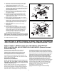
8b. Shift motor mounting base (and blower housing) back
toward coil to second set of mounting lugs on motor
support channel. Rotate blower housing up 90°.
Reattach base with screws.
9. Cut insulation from discharge air location on top panel (opening
dimensions shown in Figure 2.3 of unit manual). Insert cut piece
into opening. Apply adhesive per manufacturer's instructions.
Attach cover plate to front of unit.
10. Bend both flanges 90° into cabinet using 3" duct-bill
pliers. Pliers should engage full jaw depth (1-1/4") and
be centered on flange.
11. Insert blower housing into top panel. Reattach panel to unit.
12. Align hole in blower housing with lower slot in motor
support channel flange. Attach housing to flange with
(1) previously removed screw.
13. Align (4) holes in top panel flange with holes in blower
housing. Attach with removed screws.
14. Assure blower wheel is centered in inlet and discharge of
blower housing. If required, adjust by loosening (4) bolts
securing motor. Shift motor and refasten. For blower
wheel adjustments, loosen set screw (not shown), shift
wheel and refasten.
15. Apply latex caulk to seal between blower housing
and top panel.
16. Reinstall electrical control box.
17. Plenum adaptor can be installed so offset faces either
end of fan coil unit. Remove backing from gasket and
mate it to fan coil unit so blower opening is centered in
plenum adaptor opening. Place plenum adaptor over
discharge opening and align with the (4) unit holes
surrounding the blower opening. Secure adaptor to
unit with sheet metal screws provided.
NOTICE: Check that all inside cabinet surfaces are covered
with insulation, add insulation if required. An uninsulated
panel will “sweat” and condensate will form on the cabinet.
18. Replace all panels and screws.
FIGURE 2.9A
STEPS 4 THRU 7: REFER TO FAN COIL UNIT INSTALLATION MANUAL
STEP 8: INSTALLING AIR DISTRIBUTION COMPONENTS (Plenum Duct and
Plenum Take-offs)
All plenum duct and supply tubing runs as well as room
terminator locations must be in accordance with air
distribution system requirements listed in Section 1 of fan
coil unit installation, operation and maintenance manuals.
Where taping is required, use UL 181A approved tape.
Tools Required: SpacePak Pliers (PTO Clip Spreader), saw
(hand or reciprocating), drill fitted with 2-1/8" arbored hole saw,
1/4" nut driver and utility knife.
Plenum Duct Installation
NOTICE: SmartSeal duct fittings are made to fit tight, assur-
ing a proper seal. Care should be taken when handling
these fittings as damage could result in an improper fit and
a difficult installation process.
All tees, elbows and branch runs must be a minimum of 24"
from the fan coil unit or any other tee, elbow or branch run.
Keep all tees and elbows to a minimum to keep system pres-
sure drop on larger layouts to a minimum. SmartSeal spiral
metal duct comes in 6-foot lengths and may be cut to length.
SmartSeal spiral metal duct can be suspended using vinyl
duct strapping or plumber’s strap. Duct should be supported
every 3 feet with a minimum of two supports per 6 foot length.
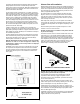
Begin installing plenum duct by sliding insulation and metalized
jacket back several inches to expose end of first straight duct
length (14" min. length). Place the straight duct length level
with and around the hemmed edge of the plenum adaptor.
Apply pressure and the straight duct length will slip into place,
stopping at the bead/pipe stop (see Figure 2.10A). Starting
at the largest radial gap between fitting and duct, use (3)
self-tapping sheet metal screws, placed 1/2" from the bead/pipe
stop and spaced evenly around the circumference of the duct
connection (see Figure 2.10B). The gasket and fittings are
designed to allow adequate room to secure the screws per
SMACNA standards. Carefully seal any holes left by
measurements, removed screws, etc.
[Suggested location for Figures 2.10A and 2.10B]
SPL-0074-B
9
16
8b
14
12
18
18
11
13
18
1015
17
SPL-0073-B
2
4
2
3
2
2
8a
7
3
6
5
SECTION 3: ATTACHING AIR PLENUM ADAPTOR
FIGURE 2.9B