
Gasketed Spiral Metal Duct System Installation Manual


4
Cover plenum adaptor with extra insulation wrap included with
straight plenum duct section. Insulation wrap is to be flush
against the unit and secured with UL 181A tape. Reposition duct
insulation and jacket to completely cover duct connection. Seal
jacket seams with UL 181A tape.
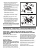
To add another length of straight duct, a coupling is required.
Slide insulation and jacketry of the previously installed straight
duct length back several inches, place the coupling level with
and inside the straight duct, and apply pressure until coupling
slips into place, stopping at the bead/pipe stop (see Figure
2.10A). Use (3) self-tapping sheet metal screws, placed 1/2"
from the bead/pipe stop and spaced evenly around the circum-
ference of the duct connection (see Figure 2.10B). Repeat
when connecting the additional length of straight duct. Cover
all connections/couplings with insulation and jacket, and seal
jacket seam with UL 181A tape.
If adding a fitting such as an elbow or tee to straight duct
lengths, a coupling is not required as the fittings come with the
appropriate gasketing installed for a proper seal when mated
with straight duct length. All fittings are manufactured to slip fit
into SmartSeal spiral duct.
Continue adding plenum lengths and other fittings as needed.
Extra insulation and jacketry is provided with the straight duct
lengths and should be used to cover all connected fittings.
Seal all jacket seams with UL 181A tape.
NOTICE: Straight plenum duct sections can be cut to length.
However, be sure to cut duct straight and remove any
resulting burrs. Failure to do so may result in an improper
seal and system failure.
Installation of end caps (at the end of all plenum runs) should
be completed after all plenum take-offs have been installed.
The duct shavings produced with plenum take-off installation
will be blown into the space to be conditioned if sealed into
duct system.
FIGURE 2.10A
Plenum Take-off Installation
Mark locations for take-offs on plenum duct. All take-off locations
must be a minimum of 18" from any plenum tee, plenum elbow or
the fan coil unit. SpacePak recommends take-offs be placed 12"
apart and that any (2) not be installed directly across from each
other (on opposite sides of the duct).
At marked location cut 2-1/8" diameter hole with hole saw.
Begin in reverse to cut through jacket sleeve and insulation
and stop when hole saw teeth contacts duct. Switch drill to
forward and continue to cut through duct. Remove any loose
duct shavings around hole.
With utility knife, make (4) 2" cuts into jacket and insulation
around hole (90° apart). Move insulation away from hole so the
4" diameter take-off gasket can be applied completely to duct
surface.
Remove backing from take-off gasket and press it on duct
location so as not to cover the hole.
NOTICE: Gasket must be installed to seal plenum take-off
to prevent air leakage.
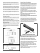
Seat take-off in hole so the curvature matches that of the duct
(see Figure 2.11 - duct shown without insulation and jacket).
Insert (1) plenum clip (green) into a slot opening, then slide
down. Apply enough pressure to take-off so clip grabs inside of
duct. Repeat the procedure with another clip opposite the first
(180°). Using SpacePak pliers secure both clips so they “click”
flush with interior of duct. Complete by inserting (2) more
plenum clips in remaining slots and install as above.
NOTICE: All four clips must be installed to assure air tight
fitting between plenum take-off and plenum.
The insulation and jacket around installed take-off will be
repositioned when attaching supply tubing/kwik-connect
assembly covered in unit’s installation, operation and mainte-
nance manual (Section 2).
After all required plenum take-offs have been installed, clear
interior duct system of loose shavings. Starting the fan coil unit,
prior to assembly of end caps, will clear the system.
Install plenum end cap at the end of each run. Connect end
cap to plenum duct by following procedure described in Plenum
Duct Installation for other plenum fittings. Tape jacket seams
with UL 181A approved tape.
Installation instructions for room terminators, sound attenuating
tubing and supply tubing are provided in installation manual
supplied with fan coil unit (Section 2).
FIGURE 2.11: TAKE-OFF INSTALLATION
FIGURE 2.10B
.
.