
Application Manual and System Selection Guide


11
Line 20 Orices Required: You must select the
terminal-orice combination from Figure 2.5 which
produces close to the number of terminators required
on Line 19 for each room. This information is also
available in Table 5 on the back of the Kwik-Way sheet.
Example (see Figure 2.4): Bedroom 4 requires 1.68
terminators, which is equal to 168% capacity. To assure
equal air distribution, we selected the combination of
two room terminators, one fully open and one with a
35% orice.
Line 21 Adjustable Dampers Required: For heating
installations, if there is a signicant difference between
the number of cooling and heating terminators on
Line 18, then adjustable dampers will have to be
used to change the air ow from the cooling season
to the heating season. Enter the number of adjustable
dampers required for each room.
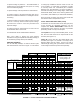
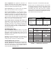
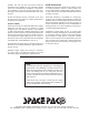
FIGURE 2.5: TERMINAL-ORIFICE COMBINATION
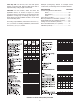
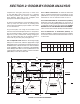
FIGURE 3.1: ESP-4860 INSTALLATION
DESIRED NUMBER
OF TERMINALS *
TERMINAL - ORIFICE
COMBINATION
.5
.65
.85
1.00
1.15
1.30
1.50
1.65
1.70
1.80
1.85
1.95
(1) .5
(1) .35
(1) .15
(1)
(1) .5 + (1) .35
(2) .35
(1) .35 + (1) .15 or (1) + (1) .5 or (3) .5
(1) + (1) .35 or (2) .5 + (1) .35
(2) .15
(2) .35 + (1) .5
(1) + (1) .15
(3) .35
2.00 (2)
* For a room with more than two (2) terminals, combinations of the above
may be used to achieve the desired fractional number.
UNIT NO. 1
UNIT NO. 2
FAN COIL UNIT
FAN COIL UNIT
NO MORE THAN
60 % OF CAPACITY
ON ONE SIDE
30 % MAX. OF
CAPACITY
MINIMUM 18"
MINIMUM 18"
PLENUM DUCT
The plenum duct can be run in practically any location
accessible for the attachment of the supply tubing. The
plenum is normally located in the attic or basement,
and it is usually more economical to run the plenum
where it will appreciably shorten the lengths of two
or more supply runs. In some two-story split level
homes, it may be advantageous to go from one level
to another with the plenum duct. Whenever necessary,
either between oors or along the ceiling, the small
size of the plenum makes it easy to box in.
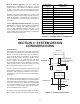
The fan coil coil unit is designed to operate with a total
external static pressure of 1.2 inches of water column.
Excessive static pressure increases the air ow in
individual runs and may cause some or all terminators
to be noisy.
For systems with a tee installed as on Unit No. 1 (Figure
3.1), the best results are obtained if not more than 60%
of the total number of system outlets are attached to any
one branch of the tee. For systems with a tee installed
as on Unit No. 2 (Figure 3.1), not more than 30% of the
total number of system outlets should be attached to
the perpendicular branch of the tee.
The larger system capacities (ESP-4860) are affected
more by higher system static pressure than the smaller
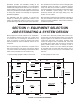
SECTION 3: SYSTEM DESIGN
CONSIDERATIONS