
Application Manual and System Selection Guide
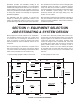

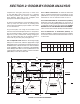

systems. The four and ve ton system should be
considered and handled as two separate smaller
units. This necessitates the installation of the plenum
tee a minimum of 18" from the unit (see Figure 3.1).
No supply runs should be installed between unit outlet
and tee.
All tees and elbows must be a minimum of 18" from
the fan coil unit or any other tee or elbow. Keep all tees
and elbows to a minimum.
SUPPLY TUBING
In the case of two-story or split-level applications, supply
tubing may run from one story to another. It is small
enough to go in stud spaces, but this is often difcult
in older homes because of hidden obstructions in stud
spaces. It is more common to run the supply tubing from
the attic down through second story closets to the rst
story terminators. Supply tubing runs in the corners of
the second story rooms can be boxed in and are hardly
noticeable since overall diameter is only 3-1/4".
At the plenum, all supply tubing connections must be a
minimum of 18" from any plenum tee, plenum elbow or
the fan coil unit.
Individual supply tubing runs must be a minimum
of 6 feet, even if the distance between the sound
attenuating tubing and plenum is less than 6 feet.
ROOM TERMINATORS
Terminators should be located in the ceiling or oor
for vertical discharge. However, ceiling locations are
not recommended for heating where ceiling height is
10 feet or more due to possible stratication and short
circuiting of air ow.
Horizontal discharge is acceptable for cooling-only
systems, but is sometimes more difcult to install. Two
excellent spots for horizontal discharge are in the soft
area above kitchen cabinets and in the top portion of
closets. Horizontal discharge is not recommended for
heating systems, as it will not maintain a proper oor-
to-ceiling temperature difference.
Terminators should always be out of normal trafc
patterns to prevent discharge air from blowing directly
on occupants. And they should not be located directly
above shelves or large pieces of furniture. Outside
wall or corner locations are recommended if the room
has more than one outside wall. Locating terminators
away from interior doors prevents short cycling of air
to the return air box.
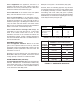
NOTE:
The Kwik-Way method is appropriate for calculating the
cooling loads of most buildings or normal structures but it
might not be appropriate when calculating loads for sun
rooms and buildings that do not comply with data and
factors in this application manual and Kwik-Way form. If
in doubt, calculate the actual cooling load using the long
form manual “J”.
Some factors may vary state to state and your design
temps may be greater. SpacePak assumes no liability for
incorrect interpretation of this manual.
260 NORTH ELM STREET • WESTFIELD, MA 01085 • TEL: (413) 564-5530 • FAX (413) 564-5818
7555 TRANMERE DRIVE • MISSISSAUGA, ONTARIO L5S 1L4 CANADA • TEL: (905) 670-5888 • FAX (905) 670-5782