
Application Manual and System Selection Guide


3
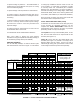
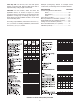
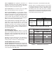
SpacePak provides the Kwik-Way Heating & Air
Conditioning sizing sheet (see Figure 1.1) to help dealers
calculate the heat gain and/or heat loss of a structure to
assure maximum comfort for the occupants. The form is
easy to use; provides an accurate analysis; and is essential
for sizing the structure and selecting the appropriate
SpacePak equipment.
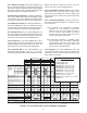
The Kwik-Way form also provides a room-by-room
analysis for selecting the appropriate number of air
outlets and balancing orices for each room. Proper
system balancing is the key to proper system operation.
Before equipment can be selected for an installation,
it is imperative that the heat gain (for cooling) and/
or the heat loss (for heating) be calculated for the
home or business in which the Space Pak system
will be installed to assure maximum comfort for the
occupants.
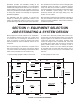
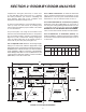
Prior to performing your calculations, complete a oor
plan of the structure, such as the one shown in Figure
1.2, which contains the following measurements (all of
which can be rounded off to the nearest foot):
1. Square footage (length x width) of each room.
The small amount of time that is spent in designing the
SpacePak system will result in a satised customer
every time. We have provided a number of extremely
important guidelines in this application manual involving
the air distribution system design, such as static
pressures, plenum duct and supply tubing runs, and
location of room outlets.
We recommend reviewing these guidelines carefully, as
they are intended to save time on the job, help obtain
the best possible installation, and provide continuous,
trouble-free operation.
SECTION 1: EQUIPMENT SELECTION
JOB ESTIMATING & SYSTEM DESIGN
2. Linear feet of exposed (outside) wall in each room.
If more than one exposed wall in each room, add the
lengths together. If the wall has two different kinds of
construction (part brick, part frame), measure each
section as though it were a separate wall. If the wall
is partially above grade and more than 3-feet below
grade, measure each section as though it were a
separate wall. If there is an open stairway alongside
an exposed wall, the entire wall area (all the way to
the ceiling of the sec-ond oor) is to be added to the
rst oor.
3. Ceiling height in each room.
DINING ROOM
306 Sq. Ft.
FAMILY
ROOM
216 Sq. Ft.
KITCHEN
198 Sq. Ft.
BED. 4
216 Sq. Ft.
BED. 3
180 Sq. Ft.
BED. 2
210 Sq. Ft.
BED. 1
357 Sq. Ft.
LIVING ROOM
580 Sq. Ft.
GARAGE
BATH
126 Sq. Ft.
65'
38'
3'x7'
3'x4' 3'x4'
3'x4'3'x4'3'x4'
3'x4'
3'x4'
3'x4'
3'x4' 5'x4'
5'x4'
3'x7'
3'x7'
8'x4'
18'
12'
11'
12'
15'
14'
15'
21'
17'
7'
18'
18'
17'
18'
12'
18'
20'
29'
7' Partition
18' Partition
N
S
W
E
FIGURE 1.2: FLOOR PLAN EXAMPLE