
Application Manual and System Selection Guide


2
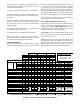
ROOM:
ROOM:
X
=
AREA
SQ FT
HEAT
BTU
COOL
BTU
HEAT COOL
NONE .15.35 .50
TOTAL STRUCTURE
AREA
SQ FT
HEAT
BTU
COOL
BTU
HEAT COOL
FACTORS
HEAT COOL
Lg x Wd
L ft exp wall
Ceiling Ht
To tal Exp wall
ITEM OF CONSTR
UCTION
Shade Exposure
N
NE & NW
E & W
SE & SW
S
1 WIND
OWS
(cooling)
Including
Glass Door
s
2 Glass Doors (heating)
3 Windows (heating)
4 Standard Doors (non-glass)
5 Par
titions (less doors & wind
ows)
6 Exposed
Wa
lls (less 1, 2, 3, 4 & 5
)
7 Ceiling/Roof
8 Floor
9 V
entilation (Mechanical)/Infiltratio
n
10 P
eople
11 A
ppliances
12 Sub-
To
tal Lines 1 - 1
1
13 Sensi
bl
e {Line12 x Duct F
actor (Fig.1.6)}
14 Heat Gain
fo
r Cooling Load (Line 13 x 1.3)
15 Equipment Selected (Fig.1.7
)
300
1200
1.3
19 Selected No. of Ter
minators (Choose the larger number from Line 18
)
18 Recommended No
. of Terminators (Line 16 ÷ 17)
17 Base Load Factors
16 Adjusted Loads: LAF (Fig. 2.3) x Line 13 and Line 14
20 Orifices Required
21 Adjustable Dampers Required
OUTDOOR UNIT :
BASE LOAD FACTOR HEATING =
Line 13 To tal Structure Heating
Recommended No. of Terminators
ROOM:
X
=
AREA
SQ FT
HEAT
BTU
COOL
BTU
HEAT COOL
NONE .15.35 .50
ROOM:
X
=
AREA
SQ FT
HEAT
BTU
COOL
BTU
HEAT COOL
NONE .15.35 .50
ROOM:
X
=
AREA
SQ FT
HEAT
BTU
COOL
BTU
HEAT COOL
NONE .15.35 .50
ROOM:
X
=
AREA
SQ FT
HEAT
BTU
COOL
BTU
HEAT COOL
NONE .15.35 .50
ROOM:
X
=
AREA
SQ FT
HEAT
BTU
COOL
BTU
HEAT COOL
NONE .15.35 .50
ROOM:
X
=
AREA
SQ FT
HEAT
BTU
COOL
BTU
HEAT COOL
NONE .15.35 .50
X
=
AREA
SQ FT
HEAT
BTU
COOL
BTU
HEAT COOL
NONE .15.35 .50
INDOOR UNIT : RECOMMENDED NO. OF TERMINATORS: SUPPLEMENTA L HEAT :
BASE LOAD FACTOR COOLING =
Lline 14 To tal Structure Heating
Recommended No. of Terminators
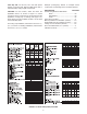
KWIK-WAY HEATING & AIR CONDITIONING SIZING SHEET
= =
FIGURE 1.1: KWIK-WAY HEATING AND AIR CONDITIONING SIZING CHART